
Subscribe to Our Youtube Channel
Related Manuals for Bartscher MC6040-5


Summary of Contents for Bartscher MC6040-5
- Page 1 MC6040-5 / MC6040-8 / MC6040-10 / HC6040-5 / HC6040-8 / HC6040-10 117900 - 117901 - 117902 117905 - 117906 - 117907...
- Page 2 Bartscher GmbH Phone: +49 5258 971-0 Franz-Kleine-Str. 28 Fax: +49 5258 971-120 Technical Support Hotline: +49 5258 971-197 D-33154 Salzkotten Germany www.bartscher.com Version: 1.0 Date of preparation: 2022-09-05...
-
Page 3: Table Of Contents
Original instruction manual Safety ......................2 Explanation of Signal Words ..............2 Safety instructions..................4 Intended Use ................... 7 Unintended Use ..................7 General information ..................8 Liability and Warranty ................8 Copyright Protection ................8 Declaration of Conformity ................ 8 Transport, Packaging and Storage .............. -
Page 4: Safety
Safety Diese Bedi enungsanlei tung besc hrei bt di e Installation, Bedi enung und Wartung des Geräts und gilt als wic htige Infor mationsquelle und N achschl agewer k. Di e Kenntnis aller enthaltenen Sic herheits hinweis e und H andlungs anweisungen schafft die Vorauss etz ung für das sichere und s ac hger echte Ar beiten mit dem Gerät. D arüber hi naus müs sen die für den Ei ns atz ber eic h des Geräts geltenden ör tlichen Unfall verhütungs vorsc hriften und allgemeinen Sicherheits besti mmungen eing ehalten wer den. Dies e Bedi enungs anleitung is t Bes tandteil des Produkts und muss i n unmi ttelbarer N ähe des Ger äts für das In¬s tall ations-, Bedi enungs-, Wartungs- und R einigungspers onal jederzeit z ugänglich auf¬bewahrt werden. Wenn das Ger ät an eine dritte Pers on weiterg egeben wird, muss die Bedi enungsanlei tung mit ausgehändigt wer den. - Page 5 Safety WARNING! The signal word WARNING warns against hazards that may lead to moderate or severe injuries or death if the hazards are not avoided. CAUTION! The signal word CAUTION warns against hazards that may lead to light or moderate injuries if the hazards are not avoided. , di e IMPORTANT! The signal word IMPORTANT indicates possible property damages,...
-
Page 6: Safety Instructions
Safety This symbol indicates situations in which persons must take care not to come into contact with hot steam which may escape during the operation of the oven. Failure to observe these instructions may result in serious injury. RISK OF BURNS — handling hot sheets with products! This symbol indicates situations where persons must be careful when handling hot sheets with hot products and liquids that may fall or spill on a person during loading or unloading. - Page 7 Safety Flammable Materials • Never subject the appliance to contact with high temperature sources, e.g.: oven, furnace, open flame, heat generating devices, etc. • To avoid fire hazard, clean the appliance regularly. • Do not cover the appliance with, e.g., aluminium foil or cloths. •...
- Page 8 Safety Improper Use • Unintended or prohibited use may cause damage to the appliance. • The appliance may only be used when its technical condition is flawless and allows for safe operation. • The appliance may only be used when all connections are executed according to rules of law in force.
-
Page 9: Intended Use
Safety Intended Use As described below, every use of the appliance for a purpose differing and/or diverging from its intended standard use, is prohibited and considered to be an unintended use. The following is an intended use: – Baking bread –... -
Page 10: General Information
General information General information Liability and Warranty All information and instructions in this instruction manual account for legal regulations in force, current level of technical engineering knowledge as well as our expertise and experience, developed over the years. If special models or additional options are ordered, or state-of-the-art technical solutions were implemented, the actual scope of delivery of the appliance may, in some circumstances, differ from descriptions and numerous drawings in this instruction manual. -
Page 11: Transport, Packaging And Storage
Transport, Packaging and Storage Transport, Packaging and Storage Delivery Check Immediately upon reception, check the delivery for completeness and possible shipping damage. In the case of visible transport damage refuse to accept the appliance or accept it conditionally. Mark and note the scope of damage in shipping documents/consignment list of the shipping company and lodge a complaint. -
Page 12: Technical Data
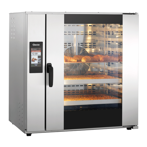
Three standard sizes of convection ovens are available: Convection ovens HC6040-5 / MC6040-5 with 5 EN 60/40 sheets Convection ovens HC6040-8 / MC6040-8 with 8 EN 60/40 sheets Convection ovens HC6040-10 / MC6040-10 with 10 EN 60/40 sheets Guaranteed Top Quality and Even Baking Results –... - Page 13 Technical Data Innovative Steaming System — 'ECO S – steam'. – Maximum steam processing for the most demanding baking professionals; – Provides greater volume in baked goods; – Noticeably longer freshness and reduced crispness of baked goods; – Optimal system for baking deep-frozen cakes; –...
- Page 14 Technical Data Version / Design • Series: – MC – 117900, 117901, 117902 – HC – 117905, 117906, 117907 • Equipment connection: 3 NAC • Heating type: hot air • Type of guide rails: crosswise • Parameters per baking phase: –...
- Page 15 Technical Data – in door • Control: – touch – multi-functional knob with LED lighting (only in 117905, 117906, 117907 appliances) • Display: – 7" LCD display – program – cleaning – timer settings – date and time • Features: –...
- Page 16 Technical Data Name: Convection baking oven MC6040-5 117900 Art. No.: Material: stainless steel Baking chamber material: stainless steel Number of guide rail pairs: Guide rail format, in mm: 600 x 400 Distance between guide rail pairs, in mm: Temperature range, max., in °C: Temperature control in °C increments:...
- Page 17 Technical Data Name: Convection baking oven MC6040-8 117901 Art. No.: Material: stainless steel Baking chamber material: stainless steel Number of guide rail pairs: Guide rail format, in mm: 600 x 400 Distance between guide rail pairs, in mm: Temperature range, max., in °C: Temperature control in °C increments: Power output, in kW: Number of programs: pre-installed / for...
- Page 18 Technical Data Convection baking oven MC6040- Name: 117902 Art. No.: Material: stainless steel Baking chamber material: stainless steel Number of guide rail pairs: Guide rail format, in mm: 600 x 400 Distance between guide rail pairs, in mm: Temperature range, max., in °C: Temperature control in °C increments: Power output, in kW: 2 x 9,55...
- Page 19 Technical Data Name: Convection baking oven HC6040-5 117905 Art. No.: Material: stainless steel Baking chamber material: stainless steel Number of guide rail pairs: Guide rail format, in mm: 600 x 400 Distance between guide rail pairs, in mm: Temperature range, max., in °C: Temperature control in °C increments: Power output, in kW: Number of programs: pre-installed / for...
- Page 20 Technical Data Name: Convection baking oven HC6040-8 117906 Art. No.: Material: stainless steel Baking chamber material: stainless steel Number of guide rail pairs: Guide rail format, in mm: 600 x 400 Distance between guide rail pairs, in mm: Temperature range, max., in °C: Temperature control in °C increments: Power output, in kW: Number of programs: pre-installed / for...
- Page 21 Technical Data Convection baking oven HC6040- Name: 117907 Art. No.: Material: stainless steel Baking chamber material: stainless steel Number of guide rail pairs: Guide rail format, in mm: 600 x 400 Distance between guide rail pairs, in mm: Temperature range, max., in °C: Temperature control in °C increments: Power output, in kW: 2 x 9,55...
-
Page 22: List Of Components Of The Appliance
Technical Data List of Components of the Appliance 1. Thermal processing chamber 2. Fan ventilation openings 3. Water spray nozzle 4. LED lighting 5. Appliance door lock 6. Door handle 7. Appliance door 8. Height-adjustable feet (4 pcs) 9. Guide rails 10. - Page 23 Technical Data 1. Thermal processing chamber 2. Fan ventilation openings 3. Water spray nozzle 4. LED lighting 5. Appliance door lock 6. Door handle 7. Appliance door 8. Height-adjustable feet (4 pcs) 9. Guide rails 10. Thermal processing chamber bottom 11.
- Page 24 Technical Data Appliance Label Description There are labels on the appliance with important information about the oven and hazardous areas, as shown in the following figure. Fig. 1 Baking chamber Generator protection protection Hood connection Internet connection High voltage Water connection USB connection Rating plate 22 / 86...
-
Page 25: Functions Of The Appliance
Installation Instructions Functions of the Appliance Crispy and crumbly fresh baked goods on all levels and on every baking sheet are successfully baked in the convection oven, especially thanks to the even air circulation created by the rapid change of direction of the fan in the baking chamber. -
Page 26: Unpacking And Positioning
Installation Instructions Unpacking and Positioning Place of Installation • The appliance is designed to operate in closed rooms and may not be used in open air nor subject to unfavourable atmospheric conditions. • The appliance may be used in properly ventilated room in order to avoid excessive accumulation of harmful substances in the air. - Page 27 Installation Instructions CAUTION! Choking hazard! Prevent children from accessing packaging materials, for instance: plastic bags and EPS elements. • Check if the appliance is undamaged. • Before positioning the appliance, check the dimensions and exact positions of the electric, water, and extraction connections. •...
- Page 28 Installation Instructions Fig. 2 26 / 86 117900...
-
Page 29: Electrical Connection
Installation Instructions Electrical Connection • Verify if the technical specification of the appliance (see the rating plate) corresponds to the characteristics of the local electric mains grid. • The power cord should be laid in a way preventing anyone from threading on it or tripping against it. -
Page 30: Water Connection
Installation Instructions appliance correctly to the 5-pin plug. If the appliance is installed in countries with a different power supply, the cable cross-section will increase accordingly and the cable will need to be replaced. • The appliance must be earthed in accordance with the safety regulations for electrical equipment. - Page 31 Installation Instructions ATTENTION! The appliance must be supplied with potable water to ensure correct operation in order to avoid limescale build-up in the injection lines, baking chamber and steam generator. A connection of a softener at the water inlet is always required! Fig.
-
Page 32: Connection Of Condensation Hood
Installation Instructions Connection of Condensation Hood WARNING! The electrical connection of the condensation hood may only be made by authorised personnel. When installing the condensation hood to the appliance, all safety regulations for the handling and operation of electrical appliances must be observed! •... - Page 33 Installation Instructions Connection of the condensation hood power supply Fig. 5 Water connection when installing the condensation hood Fig. 6 117900 31 / 86...
-
Page 34: Operating Instruction
Operating Instruction Operating Instruction Safety Indications for the User WARNING! All persons operating the appliance must be properly educated and trained by authorised personnel and must understand, respect and observe the safety rules and indications in the manual. The following safety regulations and precautions must be observed when operating the appliance: •... - Page 35 Operating Instruction – close the water valve. • At the end of the working day, disconnect the power supply and close the water tap. • Disconnect the oven from the power supply before carrying out maintenance and service work. • Maintenance, service and repair work must only be carried out by qualified personnel in accordance with safety regulations.
-
Page 36: Operation
Operating Instruction Operation Control Panels Fig. 7: Control panel of the convection Fig. 8: Control panel of the convection oven HC6040 oven MC6040 34 / 86 117900... - Page 37 Operating Instruction • Przed pier wsz ym uż yciem wycz yś cić urządz eni e i wypos ażenie zgodni e z e ws kazówkami z awartymi w pu nkcie 6 „Cz yszczen ie” . U waż ać, aby do ins tal acji elektr ycznej i s krz ynki roz dzi elcz ej ni e dostała si ę woda. N astępnie dokł adnie os usz yć urządz eni e i elementy wypos aż enia. •...
- Page 38 Operating Instruction • Przed pier wsz ym uż yciem wycz yś cić urządz eni e i wypos ażenie zgodni e z e ws kazówkami z awartymi w pu nkcie 6 „Cz yszczen ie” . U waż ać, aby do ins tal acji elektr ycznej i s krz ynki roz dzi elcz ej ni e dostała si ę woda. N astępnie dokł adnie os usz yć urządz eni e i elementy wypos aż enia. •...
- Page 39 Operating Instruction 7. SETTINGS MENU The settings menu gives access to several levels of parameters and information 8. OFF KEY By pressing and holding this key for a few seconds, the user switches the oven off. 9. STATUS BAR The status bar shows the following information: time, internet connection, USB status, date, periodical maintenance status and water filter status.
- Page 40 Operating Instruction Status Bar The status bar shows the following information: Fig. 13 1. USB connection 2. Water filter 3. Internet connection 4. Periodical maintenance 5. Current time 6. Current date USB Status Indicators Information about the colour USB indicator icons: Black USB indicator Green USB indicator Black colour of the icon...
- Page 41 Operating Instruction Internet Status Indicators Information about the colour Internet indicator icons: Black Internet indicator Green Internet indicator Black colour of the icon Green colour of the icon indicates no Internet indicates that Internet communication. communication is active and working. Red Internet indicator Red colour of the icon indicates that Internet...
- Page 42 Operating Instruction NOTE! As ovens can be installed in various combinations, the water filter must be checked manually by the user as it is used to supply water to the entire appliance. The filter icon is not an indicator of the water filter status for the entire appliance.
- Page 43 Operating Instruction NOTE! As soon as the icons light up orange, an extra precaution is automatically activated. When the oven is switched on, the 'Periodical Maintenance' or 'Water Filter Change Required' warning appears on the main menu screen. The warning is displayed and must be acknowledged by pressing the acknowledge key .
- Page 44 Operating Instruction • Przed pier wsz ym uż yciem wycz yś cić urządz eni e i wypos ażenie zgodni e z e ws kazówkami z awartymi w pu nkcie 6 „Cz yszczen ie” . U waż ać, aby do ins tal acji elektr ycznej i s krz ynki roz dzi elcz ej ni e dostała si ę woda. N astępnie dokł adnie os usz yć urządz eni e i elementy wypos aż enia. •...
- Page 45 Operating Instruction Fig. 17 1. Name of current screen 2. Information bar 3. Set baking temperature 4. Pre-heating temperature Indicator of the set baking Pre-heating temperature indicator. temperature. 5. Baking chamber temperature 6. Baking time Indicator of the current baking Indicator of the set baking time chamber temperature.
- Page 46 Operating Instruction 9. Steam generators key 10. Direct spray key The steaming intensity is set in The steaming intensity is set in intervals between 1 and 20. It can intervals between 1 and 20. It can only be set before baking. only be set before baking.
- Page 47 Operating Instruction Setting the Manual Baking Process Parameters To start the single-phase fast baking process, set the following parameters (Fig. 17): – baking temperature – time – fan speed – vapour flap – direct spraying or steaming with the generator The parameters can be set one by one.
- Page 48 Operating Instruction The total baking time is displayed on the right side of the time bar. 4. To extend the baking time, select the time add icon during or after the baking process. The end of the baking process is communicated by an acoustic signal and the 'Baking Finished' message is displayed in the information bar.
- Page 49 Operating Instruction Steaming It is not possible to use both vapour systems at the same time, therefore the icon for the vapour system that is not selected is blocked and dark grey. Regardless of the colour of the steam icons, either icon can be selected. 1.
- Page 50 Operating Instruction – During the baking process, further steaming intervals can only be added via manual steaming by pressing the 'Add Steam' icon. The colour of the steam icon indicates the different states of the system (Fig. 19). The dark grey colour of the icon indicates that the function is blocked. The grey colour of the icon with a red steam cloud indicates that the steam generator is heating up.
- Page 51 Operating Instruction The colour of the 'Add Steam' icon shows the status of the function. The dark grey colour of the icon indicates that the function is blocked. The grey colour of the icon indicates that the 'Add Steam' function is available. The red colour of the icon indicates that the 'Add Steam' function is enabled.
- Page 52 Operating Instruction The colour of the 'Extend Baking Time' icon shows the status of the function. The dark grey colour of the icon indicates that the icon is blocked (during the pre-heating phase). The grey colour of the icon indicates that the icon is available for use. The orange colour of the icon indicates that it has been selected and activated.
- Page 53 Operating Instruction Start of Baking Process WARNING! Risk of burning! When opening the appliance hot air and steam may escape. Always open the appliance door with caution, using the door handle. Always use oven mitts and protective gloves to operate the appliance. Never put hands without oven mitts into the appliance! Never slide baking sheets into the oven without oven mitts.
- Page 54 Operating Instruction – The end of the baking process is communicated by an acoustic signal and a message on the information bar: 'BAKING ENDED'. – The acoustic signal can be interrupted by touching anywhere on the screen. – Quickly, but carefully empty the oven and close the door of the oven as soon as possible so that the oven does not cool down too much before the next baking process.
- Page 55 Operating Instruction • Przed pier wsz ym uż yciem wycz yś cić urządz eni e i wypos ażenie zgodni e z e ws kazówkami z awartymi w pu nkcie 6 „Cz yszczen ie” . U waż ać, aby do ins tal acji elektr ycznej i s krz ynki roz dzi elcz ej ni e dostała si ę woda. N astępnie dokł adnie os usz yć urządz eni e i elementy wypos aż enia. •...
- Page 56 Operating Instruction Fig. 22: Baking program 1. Program number 2. Program name 3. Information bar 4. Program time 5. Add steam 6. Percentage of oven load 7. Add baking time 8. Switching on 9. Stop key 10. Undo key 54 / 86 117900...
- Page 57 Operating Instruction Editing the Baking Program You can access the 'Edit Program' list (Fig. 23) by pressing the 'Edit Program' icon in the 'Main Menu' screen (Fig. 17). Convection ovens allow you to program and activate up to 99 baking programs. Each program may consist of 6 phases of the baking process.
- Page 58 Operating Instruction Changing Program Parameters The parameters of the first phase differ slightly from those of the other phases. The menu contains the pre-heating temperature in the first line under the numerical symbols. In the other phases, the total baking time is displayed in the first line. Fig.
- Page 59 Operating Instruction program and displays the new pictogram already. 5. Preparation function 6. Fan speed In the first phase the pre-heating The fan speed is displayed. Press time is displayed, while in the this parameter to change it. The other phases the total baking time keypad will appear.
- Page 60 Operating Instruction 9. Steaming type 10. Steam intensity Shows the type of the set steaming. Shows the set steam intensity. To By pressing the icon you may change the parameter, select the change the selected steaming type. parameter by pressing it. The keypad will appear.
- Page 61 Operating Instruction Adding timer alarms Five different additional timer alarms may be set for various warnings during the baking process. The timer alarms can be set independently of the main alarm, which communicates the end of the baking process. Select any phase icon except the first phase icon, as the first phase always shows the pre-heating temperature and not the total time.
- Page 62 Operating Instruction 3. Adding a timer alarm 4. Deleting timer alarms Adding a new timer alarm to the Delete the last alarm that was program is done by selecting the added to the program by pressing 'Add New Timer Alarm' icon. The the 'Delete Last Timer Alarm' icon.
- Page 63 Operating Instruction Cleaning Programs The convection ovens have four different cleaning programs. The cleaning programs can be selected by touching the screen or by rotating and pressing the multi-function key in the cleaning menu. Fig. 29 1. Cleaning-I 2. Cleaning-II This is designed for daily cleaning.
- Page 64 Operating Instruction Cleaning with Cleaning Agent To start the cleaning program, the appliance door must be closed. If the appliance door is not closed, a warning sign appears in the display and the information bar shows 'Door Open'. When the appliance door is closed and no other alarms are detected, the status of the information bar changes to 'Press Start'.
- Page 65 Operating Instruction WARNING! Risk of scalding! During the cleaning process, the oven is filled with hot water. The appliance door must remain closed until the cleaning process is complete. The end of the cleaning process is indicated by an acoustic signal and the 'Ready' status displayed in the information bar.
- Page 66 Operating Instruction Filling with Cleaning Agent NOTE! For cleaning the appliances, we recommend Bartscher LG 50 convection oven cleaning agent, Art. No. 173286. 1. Open the appliance door carefully. 2. Pour 100 ml of the cleaning agent on the bottom of the baking chamber.
- Page 67 Operating Instruction Wash Program The wash program is a program for basic cleaning of the oven without cleaning agents. It lasts approx. 30 minutes. The duration may vary depending on the initial temperature in the baking chamber. The use of a cleaning agent is not required. Washing with water is used to clean off dust and crumbs from the previous baking process.
- Page 68 Operating Instruction After approx. 20 minutes, phase I cleaning is complete. A new screen appears with the 'Fill with Cleaning Agent' message and the requirement to wear protective gloves. The end of the cleaning process is also communicated by an acoustic signal. 7.
-
Page 69: Settings
Operating Instruction Settings Settings Menu The Settings menu can be activated by pressing the 'Settings' icon in the main menu screen (Fig. 35). The settings mode includes 10 options (Fig. 36). Fig. 35 Fig. 36 1. LOG IN/OUT 2. SCREEN BRIGHTNESS This option is intended for Press the screen brightness icon to specialised personnel who have... - Page 70 Operating Instruction 5. GENERAL INFORMATION 6. LANGUAGE Displays basic information about the Various languages may be selected. oven, such as oven type, serial Simply select the desired language number, factory number, and return to the menu using the manufacturer, year of manufacture, Undo icon.
- Page 71 Operating Instruction Parameter Settings Fig. 37 1. BASIC SETTINGS 2. PASSWORD Settings for temperature units, Passwords for service use. display mode, locked and manual programs, etc. 3. SOUND 4. GENERAL SETTINGS Buzzer settings (on/off) Condensation hood settings, door lock, vapour hood flap, steam settings.
- Page 72 Operating Instruction 7. FAN MOTOR 8. POLARITIES Setting of fan direction, fan speed Setting of the standard vapour (min./max.). extraction position. 9. VAPOUR EXTRACTION FLAP 10. CLEANING Setting the time to open and close Settings for cleaning parameters. the fume extraction flap. 11.
- Page 73 Operating Instruction Fig. 38 1. ACTIVATION 2. START TIME Parameter 16.07 can be used to Parameter 16.08 can be used to set enable or disable pre-heating. If the the time by which the appliance oven has already been pre-heated, should be ready for operation. the parameter automatically switches to OFF.
- Page 74 Operating Instruction Pop-up menu before the oven is switched off: Fig. 39 1. DAY SELECTION 2. TIME Indicator of the day for which Shows the time for which the automatic pre-heating is activated. appliance is ready for operation. 3. PROGRAM NUMBER 4.
- Page 75 Operating Instruction Data Transfer File transfer is carried out via the USB port. A USB flash drive is required for file transfer. The volume can be up to 32 GB. NOTE! Ensure that the USB flash drive is empty before copying programs to it. The transfer of programs may only be carried out by authorised personnel with an admin password.
- Page 76 Operating Instruction Fig. 40: Data transfer Fig. 41: Program Fig. 42: Transfer selection completed The program is now transferred to the USB drive. 6. If pictograms and sounds are also to be transferred to another oven, 'SOUND' and 'IMAGES' must be selected before transferring. The options 'LOGS' or 'PARAMETERS' cannot be selected with the admin password, as these options are for service only! 7.
- Page 77 Operating Instruction Error Detection Fig. 43: Manual mode with error display Fig. 44: Main menu with error display If an error occurs during the manual baking process, the error message is displayed in the information bar. The information bar shows the name and number of the error that occurred (Fig.
- Page 78 Operating Instruction The following table describes the possible error messages: Error number Error description Basic setting ERR01 TF1 Chamber thermal fuse ERR02 TF2 Steam generator thermal fuse ERR05 BIM1 Fan motor 1 pre-heating ERR06 BIM2 Fan motor 2 pre-heating ERR07 TP1 OVR Chamber temperature too high ERR08 TP1 UNDR Chamber temperature too low...
- Page 79 Operating Instruction ERR44 FQ1 - Out of phase ERR45 FQ1 - OVT High voltage ERR46 TP1 OVERHEAT Chamber temperature too high ERR48 TP3 OVERHEAT Steam generator temperature too high ERR49 TP4 OVRH ERR50 TP5 OVRH ERR51 TP6 OVRH ERR52 TP7 OVRH ERR53 TP8 OVRH ERR54...
-
Page 80: Cleaning And Maintenance
Cleaning and Maintenance ERR72 FQ2-OVT ERR73 FQ2-GFT ERR74 FQ2-COL ERR75 FQ2-OVT ERR76 TRIAC2 28 ERR77 TRIAC2 35 ERR78 TRIAC2 36 ERR79 TRIAC2 37 ERR80 TRIAC2 T ERR90 TOUCH ERR91 ENCODER Tab. 1 Cleaning and Maintenance Safety Instructions for Cleaning • Before cleaning, disconnect the appliance from the power supply. -
Page 81: Cleaning
Cleaning and Maintenance WARNING! The appliance must always be cooled down internally and externally to room temperature (approx. 25°C) before cleaning! Cleaning Daily Cleaning WARNING! After daily use, the oven must be cooled to room temperature (approx. 25°C) before cleaning. The following appliance components must be cleaned daily: –... - Page 82 Cleaning and Maintenance Inner Glass Pane of the Appliance Door We recommend that you clean the inner glass pane of the appliance door at least once a month; proceed as follows: 1. Open the appliance door wide. 2. Pull out (without removing) the two Teflon-coated locking tabs located on the inner glass pane of the appliance door and rotate them 180°.
- Page 83 Cleaning and Maintenance Control Panel Regular cleaning of the control panel is necessary for good performance and good visibility on the screen. 1. Clean the control panel only with a soft, slightly damp cloth. ATTENTION! Do not use any cleaning agents to clean the control panel. Condensate Collecting Tank Fig.
- Page 84 Cleaning and Maintenance Baking Sheets 1. Remove the used oven sheets, grill grates and food containers from the appliance. 2. Clean them according to the instructions of manufacturers of respective appliances. Monthly Cleaning Housing 1. Clean the outside of the oven with a damp, soft cloth or with a mild cleaning agent for degreasing metal surfaces.
- Page 85 Cleaning and Maintenance The rear wall (fan cover) of the baking chamber can also be removed for cleaning. 3. Loosen manually the four large fixing screws at the rear wall (fan cover) (Fig. 49). 4. Carefully remove the rear wall (fan cover|) from the appliance and clean it.
-
Page 86: Maintenance
Cleaning and Maintenance Fig. 50 Fig. 51 Maintenance ATTENTION! The following maintenance and cleaning work must only be carried out by qualified and specialised personnel and never by the user of the appliance! Cleaning the Condensate Collecting Tank with Trap at the Oven Rear Wall Every 3–6 months, a preventive service inspection and cleaning of the outlet channel and the condensate collecting tank with trap, located at the rear of the oven, should be carried out. - Page 87 Cleaning and Maintenance Cleaning the Oven Electrical Components Off of Flour and Other Soilings Every 3–6 months, carry out a preventive service inspection of the oven and cleaning inside the electrical parts of the oven (control cabinet). These service inspections and cleaning works should be carried out especially if the regulations for the correct and safe setting up of the oven and safety measures for a safe working environment are not met and observed.
-
Page 88: Disposal
Disposal Disposal Electrical Appliance Electric appliances are marked with this symbol. Electrical appliances must be disposed of and recycled in a correct and environmentally friendly manner. You must not dispose of electric appliances with household waste. Disconnect the appliance from the power supply and remove power cord from the appliance.
Need help?
Do you have a question about the MC6040-5 and is the answer not in the manual?
Questions and answers