Table of Contents
Advertisement
Quick Links
Advertisement
Table of Contents

Related Manuals for Fransgard TI-6000


Summary of Contents for Fransgard TI-6000
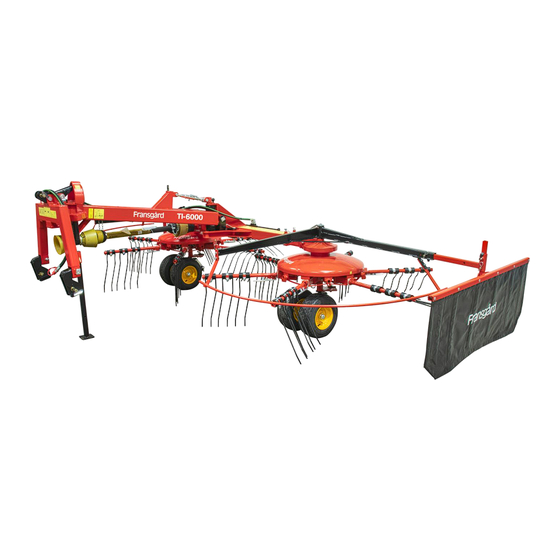
- Page 1 Fransgård Manual TI-6000 Universal TI-6000Hydr Haymaker...
- Page 2 Fransgård Maskinfabrik A/S Fredbjerg DK - 9640 Farsø Phone: +45 98 63 21 22 www.fransgard.dk E-mail mail@fransgard.dk...
-
Page 3: Table Of Contents
LIST OF CONTENTS Page Technical Specifications ................1 Safety Precautions ..................2 Introduction ....................2 Assembly instruction ................. 2-3 Working position ................... 3 Pos.1: Raking into Side Swaths ..............3 Pos.2: Raking into 2 Swaths ................ 3 Pos.3: Raking into Central Swaths ............3-4 Pos.4: Spreading .................. -
Page 4: Safety Precautions
Retighten bolts and check adjustments after approx. 5 hours of operation. Only use original Fransgård spare parts. INTRODUCTION The Fransgård Combirake model TI-6000 is one of the fastest and Figure 2: Remember to tighten most effective combirakes on the global market, and has all the chains working functions. -
Page 5: Working Position
The machine is set in working position 3. at the factory. See also the mounting/spare parts drawings on the following pages. WORKING POSITION The TI-6000 combirake has two work settings for the three-point suspension: A: Top-link attachment in fixed position. B: Top-link attachment in floating position. - Page 6 Positioned at an angle behind the tractor Figure 6: Position 1 - The machine always runs obliquely behind the tractor (adjust bolt 42452). The wheels are adjusted so that they run parallel to the direction of travel as illustrated in Figure 6. The right guard bar must be mounted and the left guard bracket must be mounted and adjusted in the middle hole of the bracket (42456).
-
Page 7: Pos.2: Raking Into 2 Swaths
POS. 2: RAKING INTO 2 SWATHS Figure 9: Position 2 – Placed behind the tractor. When raking into double swaths, adjust the machine to the maximum working width (cylinder 42451), and have the rake running straight behind the tractor (adjust bolt 42452). – see figure 9 – if necessary. The right-hand protective bracket should have been fitted, while the left-hand protective bracket should be fitted and adjust in the outermost hole on the mounting (42456). - Page 8 POSITION 3: RAKING INTO CENTRAL SWATHS Figur 12: Position 3 – Placing behind the tractor. When raking into central swaths, the machine always run straight behind the tractor (adjust bolt 42452). The rotors rotate in opposite directions (lever on reversing gear 42509), as shown in figure 13.
-
Page 9: Pos.4: Spreading
POS. 4: SPREADING Figure 17: Position 4 - Placing behind the tractor. When spreading, the machine runs straight behind the tractor (adjust bolt 42452). The rotors rotate in opposite direction (lever on reversing gear 42509), as shown on figure 13. The rotor is engaged in the reversing gear in such a way the pick-up springs cannot touch each other. -
Page 10: Transport Position
TRANSPORT POSITION Change-over from working position to transport position is as follows: Telescope small cylinder (42411) completely. Telescope large cylinder (42451) completely. Remove bolt (42452) and swing the machine back until locking pawl (42439) engages., as illustrated on figure 20. Remove retainer (42492), turn right-hand protective bracket in behind the tractor. -
Page 11: Ordering Spare Parts
ORDERING SPARE PARTS The spare part order must contain the following information: 1. Machine type. 2. Spare part number and description-possibly dimensions and number of parts. LUBRICATION AND MAINTENANCE Lubricate PTO shaft after every 10 hours of operation, and lubricate the indicated lubrication points as and when required.
Need help?
Do you have a question about the TI-6000 and is the answer not in the manual?
Questions and answers