Table of Contents
Advertisement
Quick Links
INSTALLATION INSTRUCTIONS
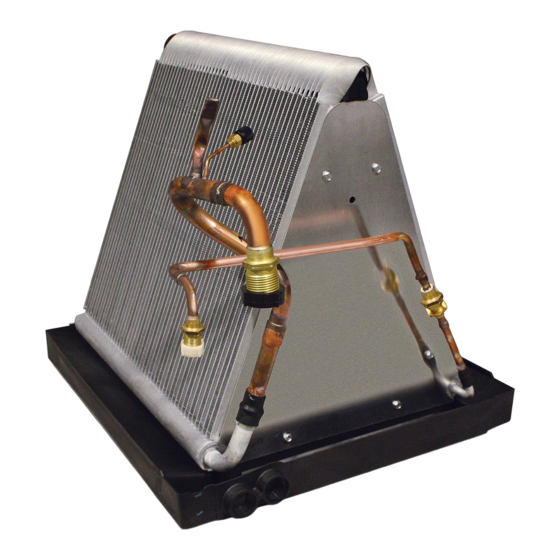
C8QA Series Split System Uncased Indoor Coils - Quick Connect
IMPORTANT
ATTENTION INSTALLERS:
It is your responsibility to know this product better than your customer. This includes being
able to install the product according to strict safety guidelines and instructing the customer on
how to operate and maintain the equipment for the life of the product. Safety should always be
the deciding factor when installing this product and using common sense plays an important
role as well. Pay attention to all safety warnings and any other special notes highlighted in the
manual. Improper installation of the furnace or failure to follow safety warnings could result
in serious injury, death, or property damage.
These instructions are primarily intended to assist qualified individuals experienced in the
proper installation of this appliance. Some local codes require licensed installation/service
personnel for this type of equipment. Please read all instructions carefully before starting the
installation. Return these instructions to the customer's package for future reference.
DO NOT DESTROY. PLEASE READ CAREFULLY AND KEEP IN A SAFE PLACE FOR FUTURE REFERENCE.
Advertisement
Table of Contents

Related Manuals for Nortek C8QA Series


Summary of Contents for Nortek C8QA Series
- Page 1 INSTALLATION INSTRUCTIONS C8QA Series Split System Uncased Indoor Coils - Quick Connect IMPORTANT ATTENTION INSTALLERS: It is your responsibility to know this product better than your customer. This includes being able to install the product according to strict safety guidelines and instructing the customer on how to operate and maintain the equipment for the life of the product.
- Page 2 Installer must comply with safety codes and wear WARNING: appropriate safety equipment (safety glasses, work gloves, fire extinguisher, etc.) when performing brazing The C8QA series uncased indoor coil is charged operations. at the factory with an R-410A refrigerant • Read the Installation Instructions supplied with the holding charge to prevent entrance of moisture furnace or air handler.
- Page 3 GENERAL INFORMATION COIL INSTALLATION C8QA series coils are designed for upflow or downflow applications and incorporate single shot coupling WARNING: refrigerant connections for easy installation. ELECTRICAL SHOCK, FIRE OR EXPLOSION • Verify that the coils orifice size is suitable for application HAZARD with the intended outdoor unit.
- Page 4 8. Cut the floor opening for the refrigerant lines and drain line. See Figure 1. 9. Connect the refrigerant lines as outlined in the Refrigerant Line Connection section (page 4). Downflow Furnace with Integral Coil Cabinet or Optional Cabinet 1. Disconnect all electrical power to the furnace. 2.
- Page 5 Orifice Removal & Installation If the orifice must be replaced, follow the steps below. NOTE: Factory supplied orifice sizes are listed in Table 1 (page 7). 1. Connect only the suction line coupling to the coil 2. Reclaim the holding charge from the coil and suction vapor line through the Schrader port using the methods approved under the RefrigerantTransition and Recovery Certification Program.
- Page 6 Condensate Drain Air Filter Air filters are not supplied as an integral part of this coil; however, an air filter kit is available. Refer to the CAUTION: Replacement Parts List for available part numbers. The coil must be level to ensure proper The filter must be installed upstream of the coil and condensate drainage.
- Page 7 COIL SPECIFICATIONS & DIMENSIONS C8QA- Nominal Capacity (BTUH) 24,000 30,000 36,000 42,000 Nominal Airflow (CFM) 1,000 1,200 1,400 18 1/8 18 1/8 18 1/8 18 1/8 W - Width (in.) H - Height (in.) 24 3/4 19 1/2 19 1/2 19 1/2 19 1/2 D - Depth (in.)
- Page 8 INStaLLeR: PLeaSe LeaVe tHeSe INSTRUCTIONS WITH THE EQUIPMENT OWNER. Specifications & illustrations subject to change without notice or incurring obligations. O’ Fallon, MO | Printed in U.S.A. (02/12) 709280A (Replaces 7092800)
Need help?
Do you have a question about the C8QA Series and is the answer not in the manual?
Questions and answers