Table of Contents
Advertisement
Quick Links
SINGLE PHASE ELECTRIC HEATED MODELS ONLY
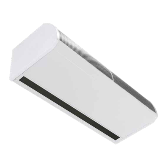
GUARDIAN GB, GR AND GS
COMMERCIAL AIR CURTAIN RANGE
INSTALLATION MANUAL
BS EN ISO 12100:2010 Safety of machinery.
BS EN 60204-1:2018 Safety of machinery. Electrical equipment of machines.
BS EN 55014-1:2017 Electromagnetic compatibility.
BS EN 60335-2-30:2009+A11:2012 Safety. Requirements for room heaters to the following
European CE directives- 2006/95/EC - low voltage; 2014/30/EU - electromagnetic compatibility
Please read this document carefully before commencing installation, commissioning and/or servicing.
Leave it with the end user/site agent to be placed in their premises technical file after installation.
WARNING
Improper installation, adjustment, alteration, service or maintenance can cause property damage, injury or death.
All work must be carried out by appropriately qualified persons.
The manufacturer does not take any responsibility in the event of non-observance of the regulations concerning the connection of the apparatus causing a
dangerous operation possibly resulting in damage to the apparatus and/or environment in which the unit is installed.
MANUAL PART NO. D301299 ISS D
Advertisement
Table of Contents

Related Manuals for Nortek Reznor GUARDIAN GB


Summary of Contents for Nortek Reznor GUARDIAN GB
- Page 1 SINGLE PHASE ELECTRIC HEATED MODELS ONLY GUARDIAN GB, GR AND GS COMMERCIAL AIR CURTAIN RANGE INSTALLATION MANUAL BS EN ISO 12100:2010 Safety of machinery. BS EN 60204-1:2018 Safety of machinery. Electrical equipment of machines. BS EN 55014-1:2017 Electromagnetic compatibility. BS EN 60335-2-30:2009+A11:2012 Safety. Requirements for room heaters to the following European CE directives- 2006/95/EC - low voltage;...
-
Page 3: Table Of Contents
Contents 6. Set door open temperature ......20 General Information (G) 7. Set heat on/off ........21 8. Set overtime ..........21 Guardian air curtain range ......4 9. Set time and days ........21 General product information .......4 10. Set time program ........21 Health and safety ........4 11. -
Page 4: Guardian Air Curtain Range
Guardian air curtain range Easy programming - the end users simply select whether they require the heat on or off, the required fan setting (1,2 or 3 speed), and General product information the outlet temperature setting Three models Options for BMS compatibility via Modbus •... -
Page 5: Requirements
Requirements Installation, assembly, commissioning, service and maintenance procedures must Clearance distances be carried out only by suitable For installation and maintenance clearances, competent qualified persons. please see the information on page 8 for the Unauthorised modifications GS models, page 6 for the GR models and to the appliance, or departure page 10 for the GB models. -
Page 6: Technical Data
Technical data Data Fan speed Unit 1000E-1PH 1500E-1PH 2000E-1PH All models Maximum door width L, M, H Maximum mounting height standard capacity L, M Maximum mounting height high capacity 1150 1730 2300 Maximum air volume 1440 2270 2880 1800 2700 3600 Maximum velocity at 0 metre 10.1... -
Page 7: Dimensions. Gs Surface Mounted Models
Dimensions. GS Surface mounted models Figure 2 GS Top view Figure 2.1 GS Front view Figure 2.2 GS Bottom view Reference GS 1000 GS 1500 GS 2000 1094 1620 2148 1360 1884 Figure 2.3 GS Side view >100 Table 2 GS dimensions Clearance distances It is recommended that a minimum clearance of 100mm is allowed around the top and front of the unit. -
Page 8: Dimensions. Gr Recessed Models
Dimensions. GR Recessed models Figure 3 GR Top view Figure 3.1 GR Front view Reference GR 1000 GR 1500 GR 2000 Figure 3.2 GR Bottom view 1125 1650 2177 1060 1584 2111 1360 1884 Figure 3.3 GR Side view Table 3 GR dimensions Clearance distances It is recommended that a minimum clearance of 100mm is allowed around the case. -
Page 9: Dimensions. Gb Bulkhead Mounted Models
Dimensions. GB Bulkhead mounted models Figure 4 GB Top view Figure 4.1 GB Front view Reference GB 1000 GB 1500 GB 2000 Figure 4.2 GB Bottom view 1360 1884 1060 1584 2111 1125 1650 2177 Figure 4.3 GB Side view 427-487 Clearance distances Table 4 GB Dimensions... -
Page 10: Signal Pro Display Panel Dimensions
Signal Pro display panel dimensions The Signal Pro display panel is supplied with an industry standard plastic double surface mounted socket box. Alternatively, the display panel can be flush mounted using a customer supplied plastic or metal flush conduit box as shown in Figure 5.2 Figure 5.1 Flush mounting plastic conduit Figure 5 Surface mount box box (by others) -
Page 11: Component Layout
Component layout Figure 6 Component layout GS Location Component Control panel Installer terminal block Fan motor Fan deck Resistor (1500 only) Heating element Table 5 GS & GR components Figure 7 Component layout GR Reznor, Guardian 1 Phase Electric Heat, Installation Manual, EN 2021-08, D301299 Iss D Page No 11... -
Page 12: Installation
Installation Mounting Electrical supply. Guardian GS,GR and GB air curtain units are Units require a connection to 1 phase 230V designed to be installed horizontally directly power supply only. over the door opening on the inside of the building, against a wall or ceiling. 1000 and 1500 models consume 6kW and 2000 models consume 8kW. -
Page 13: Installation Process
Installation process 1. Remove all packaging and covers Note All outer metal surfaces are covered by a protective plastic film, which must be removed before final fixing and operation of the unit. 2. GS units, Loosen (DO NOT REMOVE) the Figure 10 Dog bone screw fixing slot screws in the top of each front inlet cover [1] (see figure 9.1and 10 dog bone slot) -
Page 14: Suspending On Drop Rods
Suspending on drop rods Wall mounting bracket 1. The product is installed using 4 x M10 drop rods fitted into the fixing points in the top of casing. 2. The drop rods must completely pass through the fixing points in the case without being too long to cause damage to products inside the case. -
Page 15: Signal Pro Display Panel
Signal Pro display panel The display panel can be installed using the standard double surface box supplied with the program panel or recessed using a suitable flush mounted double conduit box. see “Figure 5.2 Surface mounting back box dimensions” on page 10 for details Figure 15.3 Mounting bracket top view Figure 15.3 shows the dimensions of the bracket section that is to be fixed to the unit... -
Page 16: Optional Wiring
Any air curtain within the network can • Protection. There are two high speed be connected with and respond to the fuses on the electric model base unit to following optional circuits: protect the switching thyristors for the heater. An external circuit breaker with •... -
Page 17: Wiring Diagram
Installer wiring - Electric heated models, single phase only Factory Connections Installer Wiring 230v 50Hz MAINS SUPPLY Programmer RJ45 Cable Keypad 900733 Guardian Signal Pro Series 1-Phase Electric - Installer Connections Figure 21 Wiring diagram electric heated Terminal Description Cable Terminal Description Cable... -
Page 18: Introduction
CONTROLLER Maximum length 100m. (Total length of cable used between display panel Introduction and last air curtain in network). The function of the display panel is to send It is recommended that this control cable is run commands to and receive status messages from up separately within its own trunking if possible, to to 16 controls in a multi heater system. -
Page 19: Keypad Buttons
Figure 25 Wiring of 2 or more networked air curtains. Keypad buttons Operation The buttons have the following functions:- In normal operation the home screen displays the status of the display panel and each connected air curtain in sequence. Each screen is displayed for two seconds. -
Page 20: User Operation
A single press of OK quickly starts OFF operation for If there is any error from the air curtain that will all air curtains, no heat and no fan, and then display in the bottom line. Errors are: returns to default display. “COMMS ERROR”... -
Page 21: Set Heat On/Off
7. Set HEAT ON/OFF, all or individually Use PLUS and MINUS to adjust minutes (00 to 59) then OK. After this OK the new Time and Day is Use PLUS and MINUS to select all or single address stored. then OK. If MENU is pressed at any time the original Time and HEAT ON starts flashing. -
Page 22: Engineers Instructions
OK returns to home screen and MENU restarts the If address was all then the sequence finishes and MENU at All On Mode. returns to engineers menu. If address was individual then next address is Engineers instructions flashing. Use PLUS and MINUS to set address, OK to modify the fab speed or MENU to exit back to Press ‘+’... -
Page 23: Set Temperature Limits
OK starts INT/EXT Timer Use PLUS and MINUS to select outside temperature limit, either Off or between 5 and 30, then OK. If outside temperature limit is set to OFF the sequence then finishes and returns to engineers menu. Use PLUS and MINUS to set INT/EXT timer then OK If outside temperature limit is set to between 5 and to return to engineers menu. -
Page 24: Display Hours Run
Use PLUS and MINUS to set blocked filter input If scan NO then the sequence returns to the interlock off or on then OK and to return to engineers menu. engineers menu. Note: This will cause the detected network type to Note: The lead air curtain controls the interlocks for be reset and rediscovered. -
Page 25: Diagnostics
Diagnostics T, Timer input (T = closed, blank = open). D, Door input (D = closed, blank = open). PLUS and MINUS with MENU enters diagnostics menu. Initial display: + and - change the air curtain displayed. MENU exits diagnostics back to normal display. All air curtain addresses are shown even if there is no AC installed. -
Page 26: Electric Air Outlet Temperature When "Outside Limit" Is Set
Function narrative of the unit: electric air outlet temperature when “outside limit” is set When ‘Outside Limit’ is set for an electric control the installer can set the outside limit temperature and the elevate at zero temperature. When the outside temperature is above the outside limit the fan will continue to run but the heat output will be off. -
Page 27: Modbus Protocol
MODBUS Protocol Function arguments — Registers The modbus hardware is configured as follows: Controller type Read only (undefined) System control • RS485 serial half-duplex interface Read only temperature • 9600 baud Outside air • 8 bits Read only temperature • even parity / no parity (see below) •... -
Page 28: Function Arguments Register
(*) A read or write to this coil causes the addressed Function arguments — Coils controller to execute a restart as if being powered Arguments which are outside the ranges for registers and coils in the lists below will cause exception code 02 error address out of range There is no response and the unit will not respond to Set if fan 1 actually... -
Page 29: Maintenance And Servicing
Maintenance and servicing Always ensure that the main 4. Check the security of all the components external electricity supply is 5. Check for any signs of deterioration and switched off and lock the switch replace components as necessary (if fitted) before commencing any maintenance on this heater 6. -
Page 30: Inlet Foam Filter Replacement Gr
Inlet foam filter replacement GR Figure 29 GS honeycomb retaining On the GR units the tabs are part of a retaining plate, peal back the tabs which retain Figure 28 GR inlet foam retaining clip 1 the honeycomb outlet remove the media 1. -
Page 31: Fault Finding
Fault finding. There are five basic checks to perform should General a fault appear on the program panel display. All Air Curtains are fitted with fuse protection These are as follows: and motor thermal protection. • Continuity: Use a multimeter to check Other faults in relation to the element, continuity between each end of the cable motor and wiring should be identified using... -
Page 32: Signal Pro Fault Codes
Signal Pro fault descriptions and remedies Description Symptom Possible cause Remedy Bad data cable Check data cables Communications No control on unit connection and plugs Replace failure Damaged cable damaged cable Air sensor cable Fan operating, no Check cable Replace Air sensor failed disconnected heat... -
Page 33: Spare Parts
Spare parts. Note Any spare part components that are not approved by the manufacturer could invalidate the approval of the appliance and validity of the warranty. General Right hand & left hand is when viewed from inside of the building, looking at the unit into the door opening. -
Page 34: Parts Replacement
Parts replacement. Warning Set the dip switch for the location and follow Ensure electrical power is the networking address settings. For more isolated from the product. information refer to the section on page 18. Heating element For access follow steps as stated in Installation Section on page 13 1. - Page 35 3. Remove the wires to the thermal cut out sensor, (two sensors on the 2 metre units) and remove the thermal cut out. 4. Remove the four securing nuts, shake proof washer and flat washer that secure the fan deck. 5.
- Page 36 Tel +44 (0)1384 489700 Fax +44 (0)1384 489707 reznorsales@nortek.com www.reznor.eu Nortek Global HVAC is a registered trademark of the Nortek Global HVAC lLmited. Because of the continuous product innovation, Nortek Global HVAC reserves the right to change product specification without due notice.
Need help?
Do you have a question about the Reznor GUARDIAN GB and is the answer not in the manual?
Questions and answers