Advertisement
Quick Links
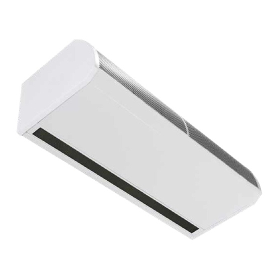
AMBIENT, LPHW AND ELECTRIC HEATED
GUARDIAN GB, GR AND GS
COMMERCIAL AIR CURTAIN RANGE
INSTALLATION MANUAL
BS EN ISO 12100:2010 Safety of machinery.
BS EN 60204-1:2018 Safety of machinery. Electrical equipment of machines.
BS EN 55014-1:2017 Electromagnetic compatibility.
BS EN 60335-2-30:2009+A11:2012 Safety. Requirements for room heaters to the following
European CE directives- 2006/95/EC - low voltage; 2014/30/EU - electromagnetic compatibility
Please read this document carefully before commencing installation, commissioning and/or servicing.
Leave it with the end user/site agent to be placed in their premises technical file after installation.
WARNING
Improper installation, adjustment, alteration, service or maintenance can cause property damage, injury or death.
All work must be carried out by appropriately qualified persons.
The manufacturer does not take any responsibility in the event of non-observance of the regulations concerning the connection of the apparatus causing a
dangerous operation possibly resulting in damage to the apparatus and/or environment in which the unit is installed.
MANUAL PART NO. D301214 ISS B
Advertisement

Related Manuals for Nortek REZNOR GUARDIAN GB Series


Summary of Contents for Nortek REZNOR GUARDIAN GB Series
- Page 1 AMBIENT, LPHW AND ELECTRIC HEATED GUARDIAN GB, GR AND GS COMMERCIAL AIR CURTAIN RANGE INSTALLATION MANUAL BS EN ISO 12100:2010 Safety of machinery. BS EN 60204-1:2018 Safety of machinery. Electrical equipment of machines. BS EN 55014-1:2017 Electromagnetic compatibility. BS EN 60335-2-30:2009+A11:2012 Safety. Requirements for room heaters to the following European CE directives- 2006/95/EC - low voltage;...
- Page 3 Contents General Information (G) Door link settings .........24 Link-group interlock ........24 Guardian air curtain range .........4 All controllers ..........24 General product information .......4 External temperature ........24 Health and safety ..........4 External temperature offset ......24 Requirements .............5 Temperature limits ........25 Clearance distances ..........5 Air return &...
- Page 4 Easy programming the end users simply select Guardian air curtain range whether they require the heat on or off (not ambient models), the required fan setting (1,2 or 3 speed), General product information and the outlet temperature setting Models Options for BMS compatible via Modbus •...
- Page 5 Requirements Installation, assembly, commissioning, service and maintenance procedures Clearance distances must be carried out only by suitable competent qualified persons. For installation and maintenance clearances, please Unauthorised modifications to the see the information on page 8 for the GS models, appliance, or departure from the page 9 for the GR models and page 10 for the GB manufacturer’s guidance on...
- Page 6 Technical data Data Fan speed Unit 1000 1500 2000 All models Maximum door width L, M, H Maximum mounting height standard capacity L, M Maximum mounting height high capacity 1150 1730 2300 Maximum air volume 1440 2270 2880 1800 2700 3600 Maximum velocity at 0 metre 10.1...
- Page 7 Ambient Models Electrical supply L, M, H 230V single phase 50Hz 1.17 1.52 2.32 Total electrical load 1.29 1.74 2.65 1.36 1.97 Weight L, M, H 48.5 External fuse size (D type MCB) LPHW Heated Models Electrical supply L, M, H 230V single phase 50Hz Maximum heating capacity standard L, M, H...
- Page 8 Dimensions. GS Surface mounted models Figure 2 GS Top view Figure 2.1 GS Front view Figure 2.2 GS Bottom view Reference GS 1000 GS 1500 GS 2000 1094 1620 2148 1360 1884 Figure 2.3 GS Side view >100 Table 2 GS dimensions Clearance distances It is recommended that a minimum clearance of 100mm is allowed around the top and front of the unit.
- Page 9 Dimensions. GR Recessed models Figure 3 GR Top view Figure 3.1 GR Front view Reference GR 1000 GR 1500 GR 2000 Figure 3.2 GR Bottom view 1125 1650 2177 1060 1584 2111 1360 1884 Figure 3.3 GR Side view Table 3 GR dimensions Clearance distances It is recommended that a minimum clearance of 100mm is allowed around the case.
- Page 10 Dimensions. GB Bulkhead mounted models Figure 4 GB Top view Figure 4.1 GB Front view Reference GB 1000 GB 1500 GB 2000 Figure 4.2 GB Bottom view 1360 1884 1060 1584 2111 1125 1650 2177 427-487 Figure 4.3 GB Side view Table 4 GB Dimensions Clearance distances It is recommended that a minimum clearance of 100mm is allowed around the case.
- Page 11 Program panel dimensions The program panel is supplied with an industry standard plastic double surface mounted socket box. Alternatively, the program panel can be flush mounted using a customer supplied metal flush conduit box as shown in Figure 5.2 Figure 5.1 Flush mounting using metal conduit Figure 5 Surface mount box box (by others) Figure 5.2 Surface mounting back box dimensions...
- Page 12 Component layout Figure 6 Component layout GS Location Component Control panel Installer terminal block Fan motor Fan deck Transformer (1500 only) Heating element Table 5 GS & GR components Figure 7 Component layout GR Page No 12 Reznor, Guardian GB GR and GS, Installation Manual, EN 2020-06, D30121 Iss B...
- Page 13 Installation Mounting Electrical supply. Guardian GS,GR and GB air curtain units are Electrically heated units require a connection to 3 designed to be installed horizontally directly over the phase 415V power supply only. door opening on the inside of the building, against a Ambient and LPHW models require a connection to wall or ceiling.
- Page 14 Installation process 1. Remove all packaging and covers Note All outer metal surfaces are covered by a protective plastic film, which must be removed before final fixing and operation of the unit. 2. GS units, Loosen (DO NOT REMOVE) the screws in the top of each front inlet cover [1] (see figure 9.1and 10 dog bone slot) then slide the left Figure 10 Dog bone screw fixing slot...
- Page 15 Suspending on threaded rods Wall mounting bracket 1. The product is installed using 4 x M10 threaded rods fitted into the fixing points in the top of casing. 2. The threaded rods must completely pass through the fixing points in the case without being too long to cause damage to products inside the case.
- Page 16 Figure 15.3 Mounting bracket top view Figure 16.1 Mounting bracket fitted to GB unit Figure 15.3 shows the dimensions of the bracket Installation details - LPHW Only section that is to be fixed to the unit using 4 x M10 x 30mm 8.8 set screws, 4 x shake prove washers and Installation of the LPHW unit is as described earlier.
- Page 17 Program panel The program panel can be installed using the • Door switches where required, to be volt free standard double surface box supplied with the and wired to INDIVIDUAL base units via normally program panel or recessed using a suitable flush closed contacts to each terminal pair ‘DOOR’.
- Page 18 Standard and high capacity fan and heat settings All units are supplied as standard capacity Electrically heated model All units have fans capable of providing standard & On the electrically heated models the fan capacity high capacity air duties (speeds Medium and High) can be adjusted in the same as the ambient by which are controlled via the program panel supplied setting the fan speed to F1, F2 or F3...
- Page 19 Wiring diagrams. NOTE External switch inputs (e.g. Timer) to be volt free and wired via normally open contacts to terminal pair marked e.g. ‘timer’ (contacts closed to enable). Remove relevant factory fitted jumper for any optional input. Installer wiring - Ambient models, single phase CONTROL BOARD (located in air curtain) 1 2 3 N...
- Page 20 Installer wiring - Electric heated models, three phase only SMARTELEC (located in air curtain) 1 2 3 N CHASSIS EARTH Comms RS485 Connections to Elements Factory Connections Installer Wiring 415v 50Hz MAINS SUPPLY SELECT RJ45 Cable Programmer Keypad 900697 Guardian Series Electric - Installer Connections Figure 21 Wiring diagram electric heated Terminal Description...
- Page 21 Installer wiring LPHW heated models, single phase CONTROL BOARD (located in air curtain) 1 2 3 N CHASSIS EARTH Factory Connections Installer Wiring 230v 50Hz MAINS SUPPLY SELECT RJ45 Cable Programmer 900699 Guardian Series LPHW - Installer Connections Keypad Figure 22 Wiring diagram LPHW heated Terminal Description Cable...
- Page 22 curtains can be linked to one program panel. Optional wiring At the Installers terminal block, remove the required The RJ45 cable is 10m as standard however it is jumper(s) and then wire in any external connections available in 2m, 20m, 30m, 50m and 100m lengths. that are required.
- Page 23 The buttons have the following functions:- SELECT Press the select button to allow navigation. Press the + button to increase a setting. – Press the – button to increase a setting. Keypad display. Operation - Ambient & LPHW Models Only On first power up, the display will show and have the following default settings: Figure 24 Air curtain address numbers.
- Page 24 SELECT Pressing the button again will display the heat single Air Curtain in a group to be the ‘master’ controller setting eg. based on links used. ‘1’ is the Air Curtain address and ‘C0’ is the default setting Engineers settings (no interlock set).
- Page 25 Normal operation This will only be displayed if there is an external sensor During normal operation mode the display is fitted, and shows the external sensor temperature set dimmed. point. Once set the Air Curtain will turn off when it reaches the set point.
- Page 26 Settings display Press – to decrease temperature set point. Min 16°C Press the SELECT button to advance through the settings. Display shows for example: 0 22 Networked air curtains Where multiple air curtains exist in a network and controlled from a single keypad, these will be detected and displayed in turn, for example: 0 25 01 22...
- Page 27 All air curtains Display Meaning Master setting Function 0 d0 Fan off Timer/BMS interlock 0 d1 Fan speed 1 Door interlock 0 d2 Fan speed 2 Timer/BMS/door interlock 0 d3 Fan speed 3 Stat interlock The temperature setting when the door link is open Timer/BMS/stat interlock circuit, is accessed by pressing the SELECT...
- Page 28 External temperature offset This function is accessed by pressing the SELECT button until the display shows This setting allows the temperature setpoint to be automatically increased as the external temperature falls to, or below, zero. For instance, a setting of 4 means a +4°C offset at 0°C.
- Page 29 MODBUS Protocol The modbus hardware is configured as follows: Modbus function codes supported Range of Codes Descriptions • RS485 serial half-duplex interface arguments • 9600 baud Read coils, read discrete • 8 bits 01, 02 Coils 1 to 24 inputs (equivalent) •...
- Page 30 (*) A read or write to this coil causes the addressed Function arguments — Coils controller to execute a restart as if being powered Arguments which are outside the ranges for registers and coils in the lists below will cause exception code 02 error address out of range There is no response and the unit will not respond to Set if fan 1 actually...
- Page 31 Maintenance and servicing Inspect the wiring for damage, chaffing of the Always ensure that the main external outer case, damage cut or crushed and security electricity supply is switched off and in the terminals lock the switch (if fitted) before commencing any maintenance on this 7.
- Page 32 Inlet foam filter replacement GR Figure 29 GS honeycomb retaining On the GR units the tabs are part of a retaining plate, peal back the tabs which retain the Figure 28 GR inlet foam retaining clip 1 honeycomb outlet remove the media from the carrier and replace.
- Page 33 Fault finding. address. General All Air Curtains are fitted with fuse protection and For fault codes refer to SmartElec fault table on page motor thermal protection. Other faults in relation to the element, motor and As the faults are mutually exclusive, the first error wiring should be identified using conventional fault- code displayed on the program panel will stay on finding techniques.
- Page 34 If a program panel has never before been run, it finding only those air curtains which are actually automatically starts in engineer’s mode when first connected and working. powered-up. To exit this mode, press and hold the E n9 [E n9] appears on the display, press and hold Button.
- Page 35 Spare parts. Note Any spare part components that are not approved by the manufacturer could invalidate the approval of the appliance and validity of the warranty. General Right hand & left hand is when viewed from inside of the building, looking at the unit into the door opening.
- Page 36 Parts replacement. Warning Ensure electrical power is isolated from the product. For access follow steps as stated in Installation Section on page 14 1. GS units, remove all of the front covers, remove the cover plate to access the control panel, installers terminal block, transformer and fan deck (motor and fans).
- Page 37 LPHW Models - Water Coil Technical info Flow/Return Temperature GS, GR & GB1000 Models 82/71 80/70 70/60 60/50 50/40 Rating 12.02 11.75 7.03 4.61 Temp. Rise ºC 14.2 13.9 11.1 Volumetric Fluid Flow m³/h Mass Fluid Flow kg/h 1009 Fluid Velocity 1.66 1.79 1.42...
- Page 38 Page No 38 Reznor, Guardian GB GR and GS, Installation Manual, EN 2020-06, D30121 Iss B...
- Page 39 Reznor, Guardian GB GR and GS, Installation Manual, EN 2020-06, D301214 Iss B Page No 39...
- Page 40 Tel +44 (0)1384 489250 Fax +44 (0)1384 489707 reznorsales@nortek.com www.reznor.eu Nortek Global HVAC is a registered trademark of the Nortek Global HVAC limited. Because of the continuous product innovation, Nortek Global HVAC reserves the right to change product specification without due notice.
Need help?
Do you have a question about the REZNOR GUARDIAN GB Series and is the answer not in the manual?
Questions and answers