Table of Contents
Advertisement
Quick Links
Revision: CP-H9HK (05-20) 1012566-B
Supersedes: CP-H9HK (08-19) PN1012566R1
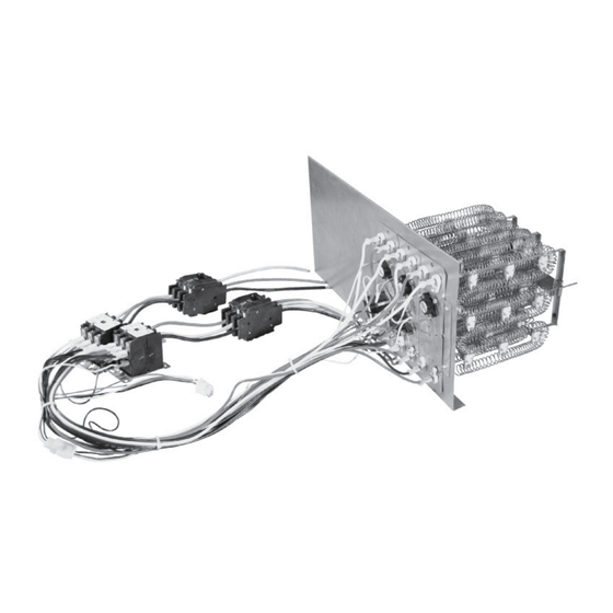
HEATER KIT INSTALLATION INSTRUCTIONS
H9HK SERIES HEATER KITS FOR INSTALLATION IN 208/240V AND 480V
LIGHT COMMERCIAL PACKAGED AIR CONDITIONERS
NOTE: Model H9HK035Q-21 shown.
IMPORTANT
ATTENTION INSTALLERS:
These instructions are primarily intended to assist qualified individuals experienced in the proper
installation of this appliance. Some local codes require licensed installation/service personnel
for this type of equipment. All installations must be in accordance with these instructions and
with all applicable national and local codes and standards.
Please read all instructions carefully before starting the installation. Return these instructions
to the customer's package for future reference.
DO NOT DESTROY. PLEASE READ CAREFULLY AND KEEP IN A SAFE PLACE FOR FUTURE REFERENCE.
Advertisement
Table of Contents

Related Manuals for Nortek H9HK Series


Summary of Contents for Nortek H9HK Series
- Page 1 Revision: CP-H9HK (05-20) 1012566-B Supersedes: CP-H9HK (08-19) PN1012566R1 HEATER KIT INSTALLATION INSTRUCTIONS H9HK SERIES HEATER KITS FOR INSTALLATION IN 208/240V AND 480V LIGHT COMMERCIAL PACKAGED AIR CONDITIONERS NOTE: Model H9HK035Q-21 shown. IMPORTANT ATTENTION INSTALLERS: These instructions are primarily intended to assist qualified individuals experienced in the proper installation of this appliance.
-
Page 2: Table Of Contents
TABLE OF CONTENTS IMPORTANT SAFETY INFORMATION INSTALLER: Please read all instructions before servicing this equipment. Pay attention to all safety warnings and IMPORTANT SAFETY INFORMATION ......2 any other special notes highlighted in the manual. Safety GENERAL INFORMATION ..........2 markings are used frequently throughout this manual to Clearances to Combustibles ...........3 designate a degree or level of seriousness and should not Wiring Diagrams ..............3... -
Page 3: Clearances To Combustibles
Approved H9HK heater kits are shipped ready to install using HEATER PART single or dual circuit electrical supply and existing factory DESCRIPTION KITS NUMBER installed terminal blocks. If dual circuit supply is desired, H9HK009Q-01 (9kw) 1011669 follow instructions included under Multiple Branch Circuit H9HK018Q-11 (18kw) 1011672 Electrical Connections section. -
Page 4: Breaker Removal
overcurrent protection of the unit supply wire must be provided at the branch circuit distribution panel and must be sized as shown in Table 3, (page 6) or on the unit rating label and according to the National Electric Code, Canadian Electrical Code and applicable local codes. - Page 5 to circuit breaker L1, L2, and L3 as shown in or attach directly to 3 pole terminal block L1, L2, and L3 if no breaker is used. 9. Carefully slide electric heat kit into place by aligning the Figure 10. Element Support Bracket Figure 7.
-
Page 6: Airflow
packaged units (on duct systems where the unit ESP pinched and foam guards are in place. is greater than that marked on the unit rating label) the 16. Replace the electric heat vestibule cover removed in Step 2 and secure with screw. heater kit may require the addition of a high static drive kit to increase blower performance. -
Page 7: Electrical Data
Electrical Data SINGLE CIRCUIT WITH NO ELECTRIC HEAT STANDARD 2-HP HIGH STATIC DRIVE STANDARD 2-HP HIGH STATIC DRIVE UNIT EQUIPPED WITH: 2-SPEED MOTOR 3-HP ECM 5-SPEED MOTOR 2-SPEED MOTOR 3-HP ECM 5-SPEED MOTOR + POWER EXHAUST + POWER EXHAUST TOTAL TOTAL TOTAL TOTAL... - Page 8 MULTIPLE CIRCUIT ELECTRICAL DATA STANDARD 2-HP 2-SPEED MOTOR COOLING CIRCUIT HEATING CIRCUIT COOLING UNIT 9 KW 18 KW 30 KW 35 KW 9 KW 18 KW 30 KW 35 KW TONNAGE VOLTAGE MCS MOP MCS MOP MCS MOP MCS MOP 208-240V 30.8 45.0...
-
Page 9: Electrical Diagrams
Electrical Diagrams SINGLE BRANCH CIRCUIT POWER SUPPLY Electric Heat 3-Pole Terminal Block Main Control Panel 3-Pole Terminal Block Black To Cooling To Single Point Power Yellow Components Supply Disconnect and Control DUAL BRANCH CIRCUIT POWER SUPPLY Electric Heat 3-Pole Terminal Block NOTE: Black, Red, &... - Page 10 Figure 14. Wiring Diagram for 9 kW, 240V, 3-Phase CP-H9HK (05-20) 1012566-B...
- Page 11 Figure 15. Wiring Diagram for 9 kW, 480V, 3-Phase CP-H9HK (05-20) 1012566-B...
- Page 12 Figure 16. Wiring Diagram for 18 kW, 240V, 3-Phase CP-H9HK (05-20) 1012566-B...
- Page 13 Figure 17. Wiring Diagram for 18 kW, 480V, 3-Phase CP-H9HK (05-20) 1012566-B...
- Page 14 Figure 18. Wiring Diagram for 30 and 35 kW, 240V, 3-Phase CP-H9HK (05-20) 1012566-B...
- Page 15 Figure 19. Wiring Diagram for 30 and 35 kW, 480V, 3-Phase CP-H9HK (05-20) 1012566-B...
- Page 16 INSTALLER: PLEASE LEAVE THESE INSTALLATION INSTRUCTIONS WITH THE HOMEOWNER Specifications and illustrations subject to change without notice or incurring obligations. ©2020 Nortek Global HVAC LLC, O’Fallon, MO. All rights reserved. CP-H9HK (05-20) 1012566-B...
Need help?
Do you have a question about the H9HK Series and is the answer not in the manual?
Questions and answers