Table of Contents
Advertisement
Quick Links
®
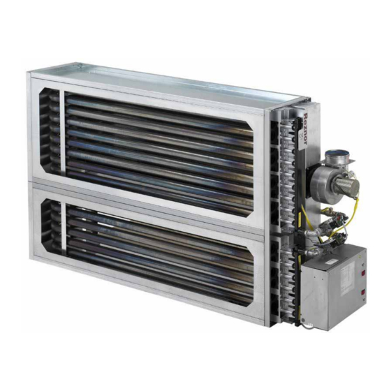
GAS-FIRED POWER VENTED UNIT HEATER
RHC DJL 8000
INSTALLATION/ COMMISSIONING/SERVICING
EU)2016/426(GAR),2009/125/EC(ErP), 2014/35/EU(LVD),and2014/30/EU(EMC)
Regulations and Directives.
The following harmonised standards have been applied:
EN 1020, EN 60335-1, EN 60335-2-102, EN 55014-1, and EN 55014-2
Please read this document carefully before commencing installation, commissioning and/or servicing.
Leave it with the end user/site agent to be placed in their premises technical file after installation.
WARNING
Improper installation, adjustment, alteration, service or maintenance can cause property damage, injury or death.
All work must be carried out by appropriately qualified persons.
The manufacturer does not take any responsibility in the event of non-observance of the regulations concerning the connection of the apparatus causing a dan-
gerous operation possibly resulting in damage to the apparatus and/or environment in which the unit is installed.
Manual Part No. D301207 Issue C
Advertisement
Table of Contents

Related Manuals for Nortek Reznor RHC DJL 8000


Summary of Contents for Nortek Reznor RHC DJL 8000
- Page 1 ® GAS-FIRED POWER VENTED UNIT HEATER RHC DJL 8000 INSTALLATION/ COMMISSIONING/SERVICING EU)2016/426(GAR),2009/125/EC(ErP), 2014/35/EU(LVD),and2014/30/EU(EMC) Regulations and Directives. The following harmonised standards have been applied: EN 1020, EN 60335-1, EN 60335-2-102, EN 55014-1, and EN 55014-2 Please read this document carefully before commencing installation, commissioning and/or servicing. Leave it with the end user/site agent to be placed in their premises technical file after installation.
-
Page 3: Table Of Contents
Contents IMPORTANT NOTICE TO INSTALLERS ....................3 1. Introduction .............................. 4 2. Technical Data ............................6 3 General Requirements ..........................10 4. Installation..............................16 5. Commissioning & Testing ........................18 6. Servicing Instructions ..........................24 7. Removal & Replacement of Parts ......................25 8. - Page 4 EC Declaration of Incorporation (Directive2006/42/EC(annexll,SubB) PROHIBITION TO PUT INTO SERVICE Nortek Global HVAC(UK)Ltd., Fens Pool Avenue, Brierley Hill, West Midlands, DY5 1QA, United Kingdom Herewith declares that: Power-vented gas-fired air heaters, type: - RHC 8000 DJL series Are destined to be incorporated in other machines(air-handlers)or to be combined with other machines(air-handling systems), and are for this reason not entirely in compliance with the machinery directive 2006/42/EC.
-
Page 5: Important Notice To Installers
IMPORTANT NOTICE TO sensory or mental capabilities or lack of experience and knowledge, unless they INSTALLERS have been given supervision or instruction concerning use of the appliance by Installers should satisfy themselves that a person responsible fort heir safety. the gas pipework installation is carried out Children should be supervised to ensure in accordance with all current legislation, that they do not play with the appliance,... -
Page 6: Introduction
• In case of persisting problems,contact A permanent electricity supply of 230 your distributor volts,50Hz,single phase is required. • The electrical isolator should only be • Gas categoriesI2H,I2E,I2E(S),I2E(R), I2Esi, used in an emergency and should not be and I2EK used for closing down the main burner, as it switches off the fan prematurely •... - Page 7 room or duct stat. However,in some applications, about 30 seconds after the call for heat, the fan control relay will activate the fan motor of the air handler. The electronic control will supervise the flame during the entire heating cycle to ensure safe operation.
-
Page 8: Technical Data
2. Technical Data 2.1. Specifications Page 6 RHC 8000 EN April 2019 D301207 Issue C... - Page 9 Country Code Approved Gas Category AT, BG, CH, CY, CZ, DK, EE, ES, FI, GB, GR, HR, IE, IT, IS, LT, LV, NO, PT, RO, SE, SI, SK, TR DE, LU, PL, RO I2Esi I2E(S)B / I2E(R)B I2EK Table 1.2 - Country Gas Category Nominal Supply Minimum Supply Gas Category...
- Page 10 2.3. Mounting Flange & Main Dimensions Figure 1 Dimensions RHC 8000(M) DJL (control side) Figure 1.2 RHC 8200M DJL (not M series) Figure 1.1 RHC 8125M,8150M,8175M DJL Gas connection Flue outlet Figure 1.3 RHC 8000 DJL (not M series) Electrical connection 8045 09 8060 12 8075 09 8075 15 8100 12 8125M 8150M...
- Page 11 Figure 2 Top view Figure 2.1 RHC 8000 DJL (not 8125M, 8150M,8175M, 8200M) Figure 2.2 RHC 8125M, 8150M, 8175M DJL Figure 2.3 RHC 8200M DJL Figure 3 - Front view RHC 8000 DJL (not 8125M, 8150M, 8175M, 8200M) Figure 3.1 - Front view RHC 8000 DJL (not 8125M, 8150M, 8175M, 8200M) RHC 8000 EN April 2019 D301207 Issue C Page 9...
-
Page 12: General Requirements
Figure 3.2 - Backside view RHC 8125M, 8150M, 8175M DJL/RJL Type 8045 09 1244 8060 12 1244 8075 09 1844 8075 15 1244 8100 12 1844 Table 3 - Dimensions Figure 3.3 Backside view RHC 8200M Type 8125M 15 1844 8150M 18 1844 8175M 21... - Page 13 Care should be exercised when designing Type ducting systems especially with regard to 8045 09 5650 1.57 the application of restriction and direction 8060 12 7500 2.08 turning fittings, i.e. elbows directly on 8075 09 9300 2.58 to the air heater, doing so can cause an 8075 15 9300 2.58...
- Page 14 • the temperature rise of the air through the enclosure (around the tubes) • the inlet air temperature passing over the heat exchanger. In function of the expected minimum inlet air temperature, the minimum required temperature rise (to avoid condensation) must be derived from the chart below). Type 8045 09 1244...
- Page 15 EURO-C 4000 R(JL) EURO-C 4000 D(JL) 20 ░C 0 ░C CONDENSATION ZONE -20 ░C TEMPERATURE RISE OVER THE HEAT EXCHANGER Figure 5. Dew point occurrence chart (condensation zone) 3.6 Combustion Air Supply & Flue System IMPORTANT: The air heater must be installed as a power The flue must be installed in vented (Type B) heater, which requires only WARNING...
- Page 16 regulations & rules in force. Table 12 shows Attention Single wall flue pipe exposed to the flue pipe sizes and maximum vent WARNING length The minimum flue length is 0.5M cold air or run through unheated (500mm) areas must be insulated. Where condensation is unavoidable, The combustion air inlet socket at the provision must be made for the...
- Page 17 3.6.2 Air Supply A constant 230 volt 50 Hertz single phase with neutral link fused electricity supply is It is important to ensure that there is an required. All heaters and controls must be adequate fresh air supply at all times for earthen.
-
Page 18: Installation
To facilitate servicing, the air heater must be fitted with an approved gas service tap and union fitting or union tap adjacent to the appliance. The inlet gas supply line must be installed so as to permit the access door to be opened and to allow removal of slide out burner assembly. - Page 19 Do not block this socket as it supplies combustion air for the WARNING: THIS APPLIANCE MUST WARNING burner BE EARTHED. WARNING The inlet must be provided with a protection grill (see figure 8) The minimum external controls required for the air heater are a room thermostat. It is essential the main input line and neutral to Type Flue Pipe...
-
Page 20: Commissioning & Testing
4.2.5 Electrical Isolator Switch ON the power to the air heater and check for correct voltage. The same Ensure that an electrical Isolator with two result should be obtained by connecting pole separation with a minimum air break the test leads between live and neutral. between poles of 3,0 mm has been fitted Connect the voltmeter test leads to adjacent to the air heater. - Page 21 Air Heater Gas Pipework The following checks should be carried out before attempting to light the air heater. The soundness of the air heater pipe work has been checked prior to leaving • Ensure that the gas supply to the air the factory.
- Page 22 5.5.1 Burner Gas Pressure Adjustment Page 20 RHC 8000 EN April 2019 D301207 Issue C...
- Page 23 The gas pressure is set for the required for modulating the burner gas pressure for heat input before the appliance leaves the firing over the range 50% to 100% of the factory, normally provided the gas supply nominal high fire burner rate. to the air heater is in accordance with the supply pressure described on the appliance Caution: Heaters must be...
- Page 24 The minimum pressure setting must be 2 Cannot obtain Maximum or High fire : adjusted first, because any adjustment of • Open circuit to regulator coil; Measure the minimum pressure setting influences the coil resistance = 127 Ω ; maximum pressure setting. •...
- Page 25 operates with the settings given in table 15 (settings are for sea level installations). When the combustion air safety control closes verifying airflow, the gas control valve will open and the burner will light. If the burner does not light, the ignition controller will lockout and must be manually reset.
-
Page 26: Servicing Instructions
Suggest that the instructions are placed Upon completion of the service carry out close to the air heater for future reference. the commissioning instructions outlined in In the absence of an appropriate location fix section 5 of this document. them to the gas service meter. WARNING: Excessive dirt build up Ensure they are not placed where they may on the inside of the burner ports... -
Page 27: Removal & Replacement Of Parts
• Remove each x-baffle and check for 6. Check the flue/combustion air system for signs of damage, warping or bending. soundness. Reseal/ replace any parts that Replace if necessary. Ensure x-baffles are not sound. are fully inserted into each burner tube. There is a tab at one end to prevent over 7. - Page 28 8. The burner rack assembly is now visible After any service work has been carried out, the air heater must be fully 9. At the bottom & top of the burner rack commissioned. See section 5 of this assembly, remove the 2 bolts that secure document.
- Page 29 Figure 12.1 - RHC 8000 models 1. Flame sensor 2. LC1 limit control (without reset) 3. Electrical wiring panel 4. Reset lockout signal lamp View Of The Control Compartment 5. Differential pressure switch 6. Burner control relay or ignition controller 7.
- Page 30 Figure 12.2 RHC 8000M models (8125M, 8150M, 8175M,8200M) 1. Flame sensor 12. Combination gas valve with pressure 2. LC1 limit control (without reset) regulation 3. Electrical wiring panel 13. Manifold & injectors 4. Reset lockout signal lamp 14. Ignition electrode 5.
- Page 31 7.2 Burner Injectors 1. Carry out steps 1 to 9 of section 7.1.1 2. Unscrew the main burner injectors. 3. Re-fit new injectors. 4. Re-assemble in reverse order. 7.3 Ignition System To access the ignition system, follow steps 1 to 3 in section 7.1..1 Igniter - refer to figure 12 and locate the igniter (on the side of the burner rack).
- Page 32 7.5 Thermal Overheat (Limit) 7.7 Combustion Air Fan (Venter) 1. Ensure gas supply to the air heater is Controls turned OFF If it is determined that the thermal overheat control needs replacing, use only authorized 2. After the air circulation fan has stopped, replacements that are designed for this switch OFF the electricity supply to the air appliance.
-
Page 33: Fault Finding
8. Fault Finding 8.1 Main Fault Finding Chart - Lockout Indicator Light Is “Off”, But Air Heater Will Not Operate WARNING Fault finding may only be carried out by appropriately qualified persons Is room therm ostat above tem perature and if so, is the tim e clock "ON"? Is there 230V bew een Check main... - Page 34 8.2 Ignition Controller Lockout Indicator Light Repeatedly Comes “On” WARNING Fault finding may only be carried out by appropriately qualified persons Is polarity of mains correct? Correct polarity Does the inlet gas pressure agree with Correct the gas the data badge supply pressure Wait 15"...
- Page 35 8.3 Limit Control Fault Finding Chart (Limit Control Trips) WARNING Fault finding may only be carried out by appropriately qualified persons Note: RHC 8000(M) air heaters are equipped with 2 limits (a recycling limit and a manual reset limit). During normal operation, neither limit should trip even if the main electric supply is interrupted during operation.
-
Page 36: Parts Listing
9. Parts Listing Description Type Part Number Application Settings 30-60621-150 8045 09 155Pa 30-60617-135 8060 12 135Pa 30-60617-150 8075 09 150Pa 30-60621-130 8075 15 135Pa 30-60617-120 8100 12 120Pa Differential pres- sure switch S3 30-60617-290 8125M 15 290Pa 30-60617-220 8150M 18 220Pa start 30-60617-75... -
Page 37: User Operating Instructions
10. User Operating 3. Ensure time switch (if fitted) is set to a Instructions ‘ON’ cycle. How the air heater works: 4. Adjust control/room thermostat to Gas is burned by an atmospheric burner desired temperature. that fires into a heat exchanger. The gas burner is controlled by a double gas valve 5. -
Page 38: Health & Safety Statement
are dependent upon the local environment The above appliances meet the Electrical Safety requirements of EN where the heater is installed. All gas appliances should be serviced at least once 60335-1. a year. 11.4 Miscellaneous In case of any damage to the appliance, it Small quantities of adhesives and sealants must be shut down completely and checked used in the product are dried and cured and... - Page 39 Characteristics: Non-corrosive, flammable with no poisonous reference-C poison Class Precautions: Avoid handling. This product can irritate and defat the skin. Prolonged contact may cause dermatitis. Avoid breathing vapor. Avoid eye contact. Do not ingest. First Aid: Skin. Wash thoroughly with soap and water.
-
Page 40: Erp Data
Page 38 RHC 8000 EN April 2019 D301207 Issue C... - Page 41 RHC 8000 EN April 2019 D301207 Issue C Page 39...
- Page 42 Tel +44 (0)1384 489250 Fax +44 (0)1384 489707 reznorsales@nortek.com www.reznor.eu Nortek Global HVAC is a registered trademark of the Nortek Global HVAC limited. Because of the continuous product innovation, Nortek Global HVAC reserves the right to change product specification without due notice.
Need help?
Do you have a question about the Reznor RHC DJL 8000 and is the answer not in the manual?
Questions and answers