Table of Contents
Advertisement
Quick Links
SINGLE PHASE ELECTRIC HEATED MODELS ONLY
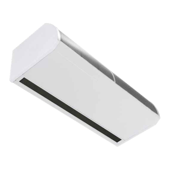
GUARDIAN GB, GR AND GS
COMMERCIAL AIR CURTAIN RANGE
INSTALLATION MANUAL
BS EN ISO 12100:2010 Safety of machinery.
BS EN 60204-1:2018 Safety of machinery. Electrical equipment of machines.
BS EN 55014-1:2017 Electromagnetic compatibility.
BS EN 60335-2-30:2009+A11:2012 Safety. Requirements for room heaters to the following
European CE directives- 2006/95/EC - low voltage; 2014/30/EU - electromagnetic compatibility
Please read this document carefully before commencing installation, commissioning and/or servicing.
Leave it with the end user/site agent to be placed in their premises technical file after installation.
WARNING
Improper installation, adjustment, alteration, service or maintenance can cause property damage, injury or death.
All work must be carried out by appropriately qualified persons.
The manufacturer does not take any responsibility in the event of non-observance of the regulations concerning the connection of the apparatus causing a
dangerous operation possibly resulting in damage to the apparatus and/or environment in which the unit is installed.
MANUAL PART NO. D301299 ISS C
Advertisement
Table of Contents

Related Manuals for Nortek RENZOR GUARDIAN GB


Summary of Contents for Nortek RENZOR GUARDIAN GB
- Page 1 SINGLE PHASE ELECTRIC HEATED MODELS ONLY GUARDIAN GB, GR AND GS COMMERCIAL AIR CURTAIN RANGE INSTALLATION MANUAL BS EN ISO 12100:2010 Safety of machinery. BS EN 60204-1:2018 Safety of machinery. Electrical equipment of machines. BS EN 55014-1:2017 Electromagnetic compatibility. BS EN 60335-2-30:2009+A11:2012 Safety. Requirements for room heaters to the following European CE directives- 2006/95/EC - low voltage;...
-
Page 3: Table Of Contents
Contents Maintenance and General Information (G) servicing (MS) Guardian air curtain range ......4 General product information .......4 Maintenance and servicing ......21 Health and safety ........4 Inlet foam filter replacement GS ....21 Requirements ..........5 Inlet foam filter replacement GR ....22 Clearance distances ........5 Honeycomb outlet replacement ....22 Electrical ............5 Important notice to installers ......5... -
Page 4: Guardian Air Curtain Range
Guardian air curtain range required fan setting (1,2 or 3 speed), and the outlet temperature setting General product information Options for BMS compatible via Modbus Models communication can be linked to optional external thermostat for proportional control in • GS Surface mounted model various set temperatures •... -
Page 5: Requirements
Requirements Installation, assembly, commissioning, service and maintenance procedures must Clearance distances be carried out only by suitable For installation and maintenance clearances, competent qualified persons. please see the information on page 8 for the Unauthorised modifications GS models, page 6 for the GR models and to the appliance, or departure page 10 for the GB models. -
Page 6: Technical Data
Technical data Data Fan speed Unit 1000E-1PH 1500E-1PH 2000E-1PH All models Maximum door width L, M, H Maximum mounting height standard capacity L, M Maximum mounting height high capacity 1150 1730 2300 Maximum air volume 1440 2270 2880 1800 2700 3600 Maximum velocity at 0 metre 10.1... -
Page 7: Dimensions. Gs Surface Mounted Models
Dimensions. GS Surface mounted models Figure 2 GS Top view Figure 2.1 GS Front view Figure 2.2 GS Bottom view Reference GS 1000 GS 1500 GS 2000 1094 1620 2148 1360 1884 Figure 2.3 GS Side view >100 Table 2 GS dimensions Clearance distances It is recommended that a minimum clearance of 100mm is allowed around the top and front of the unit. -
Page 8: Dimensions. Gr Recessed Models
Dimensions. GR Recessed models Figure 3 GR Top view Figure 3.1 GR Front view Reference GR 1000 GR 1500 GR 2000 Figure 3.2 GR Bottom view 1125 1650 2177 1060 1584 2111 1360 1884 Figure 3.3 GR Side view Table 3 GR dimensions Clearance distances It is recommended that a minimum clearance of 100mm is allowed around the case. -
Page 9: Dimensions. Gb Bulkhead Mounted Models
Dimensions. GB Bulkhead mounted models Figure 4 GB Top view Figure 4.1 GB Front view Reference GB 1000 GB 1500 GB 2000 Figure 4.2 GB Bottom view 1360 1884 1060 1584 2111 1125 1650 2177 Figure 4.3 GB Side view 427-487 Clearance distances Table 4 GB Dimensions... -
Page 10: Program Panel Dimensions
Program panel dimensions The program panel is supplied with an industry standard plastic double surface mounted socket box. Alternatively, the program panel can be flush mounted using a customer supplied metal flush conduit box as shown in Figure 5.2 Figure 5.1 Optional flush mounting using Figure 5 Surface mount box metal conduit box Figure 5.2 Surface mounting back box dimensions... -
Page 11: Component Layout
Component layout Figure 6 Component layout GS Location Component Control panel Installer terminal block Fan motor Fan deck Resistor (1500 only) Heating element Table 5 GS & GR components Figure 7 Component layout GR Reznor, Guardian 1 Phase Electric Heat, Installation Manual, EN 2021-06, D301299 Iss C Page No 11... -
Page 12: Installation
Installation Mounting Electrical supply. Guardian GS,GR and GB air curtain units are Units require a connection to 1 phase 230V designed to be installed horizontally directly power supply only. over the door opening on the inside of the building, against a wall or ceiling. Models consume either 6kW (1.0 &... -
Page 13: Installation Process
Installation process 1. Remove all packaging and covers Note All outer metal surfaces are covered by a protective plastic film, which must be removed before final fixing and operation of the unit. 2. GS units, Loosen (DO NOT REMOVE) the Figure 10 Dog bone screw fixing slot screws in the top of each front inlet cover [1] (see figure 9.1and 10 dog bone slot) -
Page 14: Suspending On Drop Rods
Suspending on drop rods Wall mounting bracket 1. The product is installed using 4 x M10 drop rods fitted into the fixing points in the top of casing. 2. The drop rods must completely pass through the fixing points in the case without being too long to cause damage to products inside the case. - Page 15 Program panel The program panel can be installed using the standard double surface box supplied with the program panel or recessed using a suitable flush mounted double conduit box. see “Figure 5.2 Surface mounting back box dimensions” on page 10 for details Figure 15.3 Mounting bracket top view Figure 15.3 shows the dimensions of the bracket section that is to be fixed to the unit...
-
Page 16: Program Panel
• External switch (ie BMS enable) where the appropriate rating should be installed required, to be volt free and wired in for the protection of the installation. See PARALLEL via normally open contacts technical data for the correct MCB to each terminal pair ‘TIMER’. (Contacts Networking closed to enable). -
Page 17: Wiring Diagram
Installer wiring - Electric heated models, single phase only 2m model only Control circuit board SMARTELEC (located in air curtain) CHASSIS EARTH Comms RS485 Factory Connections Installer Wiring 230v 50Hz MAINS SUPPLY SELECT RJ45 Cable Programmer Keypad 900706 Guardian Series 1-Phase Electric - Installer Connections Figure 21 Wiring diagram electric heated Terminal Description... -
Page 18: Air Curtain Addressing
Air curtain addressing Power-up manual reset All air curtains work on an address to The system can be reset by powering-up the communicate with the program panel and are panel whilst holding down the SELECT supplied with an default address of ‘0’. buttons. -
Page 19: Standard Settings
will now display ’Eng’ briefly. Note: Subsequent power ups will retain any entered settings in the display internal memory. In normal operation the display will show for example: This will disappear after a period of 10 minutes of inactivity on the keypad. On pressing the SELECT button the display unit... -
Page 20: All Controllers
Turn on engineers mode: increase/decrease the desired setting between C0, or 1-7 (see Table 26). If the Air Curtain is set to eg. Press and hold the button for two seconds, the display will go blank, then press SELECT the display will show ‘Eng’, release both buttons. -
Page 21: Maintenance And Servicing
Maintenance and servicing Always ensure that the main 4. Check the security of all the components external electricity supply is 5. Check for any signs of deterioration and switched off and lock the switch replace components as necessary (if fitted) before commencing any maintenance on this heater 6. -
Page 22: Inlet Foam Filter Replacement Gr
Inlet foam filter replacement GR Figure 29 GS honeycomb retaining On the GR units the tabs are part of a retaining plate, peal back the tabs which retain Figure 28 GR inlet foam retaining clip 1 the honeycomb outlet remove the media 1. -
Page 23: Fault Finding
Fault finding. For fault codes refer to page 24 General All Air Curtains are fitted with fuse protection As the faults are mutually exclusive, the first and motor thermal protection. error code displayed on the program panel will stay on until the fault has been cleared. Other faults in relation to the element, motor and wiring should be identified using Apart from the communication failure fault... -
Page 24: Fault Codes
If a program panel has never before been run, Release the buttons where upon the it automatically starts in engineer’s mode when display resumes and the system addressing first powered-up. To exit this mode, press and commences, finding only those air curtains hold the Button. -
Page 25: Spare Parts
Spare parts. Note Any spare part components that are not approved by the manufacturer could invalidate the approval of the appliance and validity of the warranty. General Right hand & left hand is when viewed from inside of the building, looking at the unit into the door opening. -
Page 26: Heating Element
Make a note of the installer terminal block 6. Remove the heating element wiring 7. Make a note of the wiring to the heating 1. Disconnect the wires from the control element including all the jumper positions panel terminals including the earth 8. - Page 27 Reznor, Guardian 1 Phase Electric Heat, Installation Manual, EN 2021-06, D301299 Iss C Page No 27...
- Page 28 Tel +44 (0)1384 489250 Fax +44 (0)1384 489707 reznorsales@nortek.com www.reznor.eu Nortek Global HVAC is a registered trademark of the Nortek Global HVAC limited. Because of the continuous product innovation, Nortek Global HVAC reserves the right to change product specification without due notice.
Need help?
Do you have a question about the RENZOR GUARDIAN GB and is the answer not in the manual?
Questions and answers