Table of Contents
Advertisement
Quick Links
Advertisement
Table of Contents

Related Manuals for Dahua TPC-KF2241-T


Summary of Contents for Dahua TPC-KF2241-T
- Page 1 Thermal Network Hybrid Thermography Cube Camera Quick Start Guide V1.0.0...
-
Page 2: Foreword
Foreword General This manual introduces the functions and operations of the thermal network hybrid thermography cube camera (hereinafter referred to as "the Camera"). Safety Instructions The following signal words might appear in the manual. Signal Words Meaning Indicates a high potential hazard which, if not avoided, will result in death or serious injury. - Page 3 and technical data. If there is any doubt or dispute, we reserve the right of final explanation. ● Upgrade the reader software or try other mainstream reader software if the manual (in PDF format) cannot be opened. ● All trademarks, registered trademarks and company names in the manual are properties of their respective owners.
-
Page 4: Important Safeguards And Warnings
Important Safeguards and Warnings This section introduces content covering the proper handling of the device, hazard prevention, and prevention of property damage. Read carefully before using the device, comply with the guidelines when using it, and keep the manual safe for future reference. Installation and Maintenance Professionals Requirements ●... - Page 5 disconnect all the cables, and then contact your local customer service center. ● Do not stuff foreign materials into the Camera to prevent a short circuit which could result in the Camera being damaged or people becoming injured. ● Use the factory default package or material of equal quality to pack the Camera when transporting it.
-
Page 6: Table Of Contents
Table of Contents Foreword ........................................II Important Safeguards and Warnings ............................IV 1 Checklist ........................................1 2 Design ......................................... 2 2.1 Dimensions ....................................2 2.2 Cables ......................................2 3 Basic Configuration ..................................... 4 3.1 Initializing Camera ..................................4 3.2 Modifying IP Address ................................5 3.3 Live Video ...................................... -
Page 7: Checklist
1 Checklist Check the package according to the following checklist. If you find something has been damaged or is missing, contact customer service. The bracket and drill required for the installation process do not come with the delivery. Please buy them if they are needed. -
Page 8: Design
2 Design 2.1 Dimensions Figure 2-1 Component dimensions (mm [inch]) 2.2 Cables The following figure of the cable is for reference only, and might differ from the actual product. - Page 9 Figure 2-2 External cable (1) Figure 2-3 External cable (2) Table 2-1 Ports description Port Port Name Connector Description Connects to standard Network port Ethernet port Ethernet cable. Inputs 12 VDC. Supply power to the device POWER Power input port —...
-
Page 10: Basic Configuration
3 Basic Configuration ● We recommend you install the Camera before configuring the network. ● The figures in this manual are for reference only, and might differ from the actual interface. For more details, see Thermal Hybrid Camera_Web Operation Manual. 3.1 Initializing Camera You can initialize the Camera through the ConfigTool, or by connecting the computer to the Camera, and logging in to the web interface with the default IP address. -
Page 11: Modifying Ip Address
3.2 Modifying IP Address Set the IP address for the network segment to allow the Camera to access the network. Step 1 Log in to the Camera web interface. Step 2 Select Setup > Network > TCP/IP. Figure 3-2 TCP/IP Step 3 Configure IP related parameters. - Page 12 You will be prompted to install a plug-in for first-time system login. Please download and install the plug-in. The web interface will refresh automatically after the plug-in is installed, and then the live video will be displayed. Figure 3-3 Live video...
-
Page 13: Installation
4 Installation 4.1 Preparations 4.1.1 Checking Installation Space and Intensity ● Make sure the place where the Camera is installed has enough space to hold the Camera and its mounting accessories. ● Make sure the mounting platform can sustain at least 8 times the weight of the Camera and its mounting structural components. -
Page 14: Installing Camera
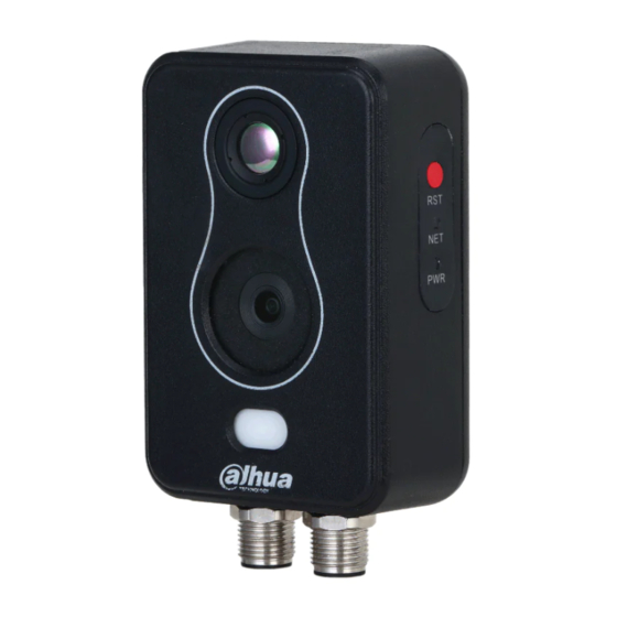
4.2 Installing Camera Avoid dropping objects such as parts and tools of the Camera from high altitudes during installation to avoid people getting hurt and the Camera being damaged. 4.2.1 Restoring to Default Settings Press the reset button for more than 10 s to reset the Camera to factory settings. Figure 4-1 Component Network indicator: It flashes orange when the network is connected. -
Page 15: Surface Installation
Figure 4-2 Magnetic installation 4.2.2.2 Surface installation You can install the Camera with screws and nuts that come with the Camera. Step 1 Paste the positioning map. Choose a suitable mounting surface, and then paste the positioning map to the surface. Drill the holes according to the label signs. - Page 16 Figure 4-4 Secure the Camera Step 3 Remove the label. After attaching the Camera to the mounting surface, remove the label from the lens. Figure 4-5 Remove the label...
-
Page 17: Alarm Configuration
5 Alarm Configuration The Camera can link to alarm output devices to report alarms when alarms are triggered from external alarm input devices. Cut off the power before connecting the cables. Step 1 Connect the alarm input device to the alarm input port of I/O cable. Alarm input: Receives on-off signals from external alarm devices, and supports NO and NC alarm input. - Page 18 Figure 5-3 Alarm setting...
-
Page 19: Appendix 1 Lightning And Surge Protection
Appendix 1 Lightning and Surge Protection The Camera adopts TVS lightning protection technology. It can effectively prevent damage from various pulse signals below 6000 V, such as a sudden lightning and surge. However, you still need to take necessary precaution measures in accordance with your local electrical safety code when installing the Camera in outdoor environment. - Page 20 Figure 1-1 Lightening protection...
-
Page 21: Appendix 2 Cybersecurity Recommendations
Appendix 2 Cybersecurity Recommendations Mandatory actions to be taken for basic device network security: 1. Use Strong Passwords Please refer to the following suggestions to set passwords: ● The length should not be less than 8 characters. ● Include at least two types of characters; character types include upper and lower case letters, numbers and symbols. - Page 22 the risk of ARP spoofing. 8. Assign Accounts and Privileges Reasonably According to business and management requirements, reasonably add users and assign a minimum set of permissions to them. 9. Disable Unnecessary Services and Choose Secure Modes If not needed, it is recommended to turn off some services such as SNMP, SMTP, UPnP, etc., to reduce risks.
Need help?
Do you have a question about the TPC-KF2241-T and is the answer not in the manual?
Questions and answers