Table of Contents
Advertisement
Quick Links
Advertisement
Table of Contents

Related Manuals for Dahua TPC-SD2221-TB3F4


Summary of Contents for Dahua TPC-SD2221-TB3F4
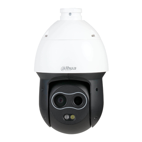
- Page 1 Thermal Hybrid Speed Dome Quick Start Guide V1.0.0...
-
Page 2: Regulatory Information
Regulatory Information The regulatory information herein might vary according to the model you purchased. Some information is only applicable for the country or region where the product is sold. FCC Information Changes or modifications not expressly approved by the party responsible for compliance could void the user's authority to operate the equipment. -
Page 3: Foreword
Foreword General This Quick Start Guide (hereinafter referred to be "the Guide") introduces the functions, installation and operations of the camera. Safety Instructions The following categorized signal words with defined meaning might appear in the Guide. Signal Words Meaning Indicates a medium or low potential hazard which, if not avoided, could result in slight or moderate injury. - Page 4 regions. For detailed information, see the paper manual, CD-ROM, QR code or our official website. If there is inconsistency between paper manual and the electronic version, the electronic version shall prevail. All the designs and software are subject to change without prior written notice. The product updates might cause some differences between the actual product and the Guide.
-
Page 5: Important Safeguards And Warnings
Important Safeguards and Warnings This chapter describes the contents covering proper handling of the device, hazard prevention, and prevention of property damage. Read these contents carefully before using the device, comply with them when using, and keep it well for future reference. Installation and Maintenance Professionals Requirements All the installation and maintenance professionals must have qualification certificate or experiences of installing and maintaining CCTV system, electric apparatus in the explosive gas... - Page 6 Please don’t block the ventilation opening near the device, which is to avoid heat accumulation for the device. Please don’t install the device near the place with heat source, such as radiator, heater, stove or other heating equipment, which is to avoid fire. Please don’t aim the lens at intense radiation source directly (such as sun, laser and ...
- Page 7 Around 2.5m long control cable is reserved when the device is delivered out of factory, it should use explosionproof flexible tube or armor cable to protect when the control cable is connected to the explosionproof control cabinet. Please cut off power before device maintenance and overhaul. It is prohibited to open the cover with power on in the explosion environment.
-
Page 8: Cybersecurity Recommendations
Cybersecurity Recommendations Cybersecurity is more than just a buzzword: it’s something that pertains to every device that is connected to the internet. IP video surveillance is not immune to cyber risks, but taking basic steps toward protecting and strengthening networks and networked appliances will make them less susceptible to attacks. - Page 9 Enable Account Lock The account lock feature is enabled by default, and we recommend you to keep it on to guarantee the account security. If an attacker attempts to log in with the wrong password several times, the corresponding account and the source IP address will be locked. Change Default HTTP and Other Service Ports We suggest you to change default HTTP and other service ports into any set of numbers between 1024~65535, reducing the risk of outsiders being able to guess which ports you...
- Page 10 14. Construct a Safe Network Environment In order to better ensure the safety of equipment and reduce potential cyber risks, we recommend: Disable the port mapping function of the router to avoid direct access to the intranet devices from external network. The network should be partitioned and isolated according to the actual network needs.
-
Page 11: Table Of Contents
Table of Contents Regulatory Information ..........................I Foreword ..............................II Important Safeguards and Warnings ....................IV Cybersecurity Recommendations ......................VII 1 Unpacking the Box ..........................1 2 Design ..............................2 Dimensions ........................... 2 2.1.1 Camera ..........................2 2.1.2 Brackets ..........................2 Cable ............................. -
Page 12: Unpacking The Box
Unpacking the Box Refer to the following checklist and check the package. If you find device damage or any loss, contact the after-sales service. Figure 1-1 Checklist Table 1-1 Checklist description Name Name Name Camera Power cable Waterproof connector — —... -
Page 13: Design
Design Dimensions 2.1.1 Camera Figure 2-1 Dimensions (mm [inch]) 2.1.2 Brackets We do not provide brackets in the packing box and if you need them, purchase them separately. Brackets for different installation methods are as follows. Figure 2-2 Wall-mount bracket (mm [inch]) Design 2... - Page 14 Figure 2-3 Pole-mount bracket (mm [inch]) Figure 2-4 Corner-mount bracket (mm [inch]) Design 3...
-
Page 15: Cable
Figure 2-5 Ceiling-mount bracket (mm [inch]) Cable Cable type might vary with different cameras, and the actual product shall prevail. Figure 2-6 Cable ports Please refer to Table 2-1 for more details about the cable function. Table 2-1 Cable ports description Port Port name Connector... - Page 16 Port Port name Connector Function description Generally it outputs analog video Analog VIDEO OUT signal, it can connect to TV monitor video output to check image. Ethernet Network port Connect to standard Ethernet cable. port Input audio signal, receive analog AUDIO IN Audio input audio signal from sound pick-up and...
-
Page 17: General Configuration
General Configuration Initializing Camera You need to initialize your Camera and set the user password when logging in for the first time. You can use ConfigTool or web to achieve initialization. Here initialization by web is taken as an example. It fails to use the Camera if the Camera is not initialized. -
Page 18: Modifying Ip Address
In order to reset password, input email address properly and update in Email Address time. Step 3 Click Save to finish initialization. Modifying IP Address In order to make the camera get access to network, please plan IP address reasonably according to the actual network environment. - Page 19 It will prompt you to install plug-in for the first system login, please save and install plug-in according to prompt. The WEB interface will refresh automatically after plug-in installation is completed, then live video will show up. Figure 3-3 The live interface General Configuration 8...
-
Page 20: Installation
Installation Make sure the mounting surface is strong enough to hold at least eight times of the camera weight. The following figure is for reference only, and the actual product shall prevail. Cable Preparation Selecting Needed Video Cable ... -
Page 21: Fixing Camera
Please check if the waterproof ring is installed properly before closing the cover, otherwise, it will affect the waterproof performance of the device. Figure 4-1 Installing SD card Table 4-2 Camera component list Name Name Reset hole Micro SD card slot 4.2.2 Fixing Camera The hybrid speed dome supports four installation modes which are wall mount, hang mount, corner mount and pole mount. - Page 22 Figure 4-2 Wall-mount installation Installation 11...
- Page 23 Figure 4-3 Pole-mount installation Installation 12...
- Page 24 Figure 4-4 Corner-mount installation Figure 4-5 Ceiling-mount installation Installation 13...
-
Page 25: Connecting Cable Ports
4.2.3 Connecting Cable Ports Refer to “2.2 Cable” and connect each cable port to corresponding cables. Then use the insulting tape to seal each port to prevent water leakage. 4.2.4 Installing Waterproof Connector Figure 4-6 Installing waterproof connector for network port Installation 14... -
Page 26: Configuring Alarm
Configuring Alarm It has to cut off power first when connecting cables. Alarm Input and Output Connection Description Step 1 Connect alarm input device to alarm input port of I/O cable. Step 2 Connect alarm output device to alarm output port of I/O cable. Alarm output is relay switch output, and the alarm output port can only be connected to NO alarm device. - Page 27 Alarm output: port ALARM_OUT and ALARM_COM form a switch, which can be used to provide alarm output. Normally the switch is on, and the switch will be off when there is alarm output. Figure 5-3 Alarm output Configuring Alarm 16...
-
Page 28: Appendix 1 Lightening And Surge Protection
Appendix 1 Lightening and Surge Protection This series speed dome adopts TVS lighting protection technology. It can effectively prevent damages from various pulse signals below 6000V, such as sudden lighting and surge. While maintaining your local electrical safety code, you still need to take necessary precaution measures when installing the speed dome in the outdoor environment. - Page 29 Appendix figure 1-1 Lightening protection Lightening and Surge Protection 18...
Need help?
Do you have a question about the TPC-SD2221-TB3F4 and is the answer not in the manual?
Questions and answers