
Related Manuals for NEC PG-FPL2


Summary of Contents for NEC PG-FPL2
- Page 1 User’s Manual PG-FPL2 Flash Memory Programmer Document No. U17307EJ2V0UM00 (2nd edition) Date Published December 2004 NS CP(K) 2004 Printed in Japan...
- Page 2 [MEMO] User’s Manual U17307EJ2V0UM...
- Page 3 NEC Electronics does not assume any liability for infringement of patents, copyrights or other intellectual property rights of third parties by or arising from the use of NEC Electronics products listed in this document or any other liability arising from the use of such products. No license, express, implied or otherwise, is granted under any patents, copyrights or other intellectual property rights of NEC Electronics or others.
- Page 4 GENERAL PRECAUTIONS FOR HANDLING THIS PRODUCT 1. Circumstances not covered by product guarantee • If the product was disassembled, altered, or repaired by the customer • If it was dropped, broken, or given another strong shock • Use at over voltage, use outside guaranteed temperature range, storing outside guaranteed temperature range •...
- Page 5 Regional Information Some information contained in this document may vary from country to country. Before using any NEC Electronics product in your application, pIease contact the NEC Electronics office in your country to obtain a list of authorized representatives and distributors. They will verify: •...
- Page 6 This manual is intended to give users an understanding of the basic specifications and correct use of the PG-FPL2. By using the PG-FPL2, programs can be easily erased from or written to the flash memory of an NEC Electronics 78K0S/Kx1+ Series on-chip flash memory...
- Page 7 User-designed board on which NEC Electronics on-chip flash memory microcontroller is mounted FP4 connector Abbreviation of PG-FP4 target connector (type A) FA adapter Adapter board to write programs to NEC Electronics on-chip flash Note memory microcontroller 78K0S/Kx1+ Generic name of 78K0S/KU1+, 78K0S/KY1+, 78K0S/KA1+, and 78K0S/KB1+ Note The FA adapter board is a product of Naito Densei Machida Mfg.
-
Page 8: Table Of Contents
CONTENTS CHAPTER 1 OVERVIEW......................... 10 Features ............................ 10 CHAPTER 2 HARDWARE INSTALLATION ..................11 System Requirements ......................11 Package Contents ........................11 System Configuration and Components ................12 2.3.1 FPL2 display specifications, connector, and MODE switch settings ..........12 2.3.2 FPL2-FA connector.........................13 2.3.3 Target system ..........................13 2.3.4 USB connector..........................13 2.3.5 Target cable............................13... - Page 9 Target Cable Specifications.....................57 Target Connector (FPL2-FA)....................57 FP4 Connector (FPL2-FA) ......................58 List of Interface Connections ....................59 CHAPTER 7 NOTES ON TARGET SYSTEMS ..................60 CHAPTER 8 CIRCUIT DIAGRAMS......................63 CHAPTER 9 TROUBLESHOOTING ......................65 Trouble During Setup .......................65 Trouble During Operation (Main Unit) ..................66 Trouble During Operation (Communication) .................66 APPENDIX A PRODUCT SPECIFICATIONS ..................68 A.1 Hardware Specifications ......................68...
-
Page 10: Chapter 1 Overview
CHAPTER 1 OVERVIEW The PG-FPL2 is a tool that erases and writes programs on an NEC Electronics 78K0S/Kx1+ Series on-chip flash memory single-chip microcontroller on the target board or FA adapter board. Features • The PG-FPL2 is a compact flash memory programmer for an on-chip flash memory microcontroller, and is designed for development. -
Page 11: Chapter 2 Hardware Installation
Package Contents Please verify that you have received all the parts listed in the package contents list included with the FPL2 package. If any part is missing or seems to be damaged, please contact an NEC Electronics sales representative or distributor. -
Page 12: System Configuration And Components
FP4 connector USB cable Note 1 (Mini-B type) PG-FPL2 Target system not compatible with FP4 connector Notes 1. Use the USB cable (Mini-B type) included with the QB-78K0SKX1MINI. 2. The FA adapter board is a product of Naito Densei Machida Mfg. Co., Ltd. -
Page 13: Fpl2-Fa Connector
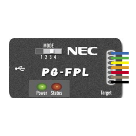
CHAPTER 2 HARDWARE INSTALLATION Target cable connector: Used to connect the connector of the target cable. USB connector: Used to connect the USB cable to be connected to the host machine. Power LED: Turned on in green when the FPL2 is connected to the host machine. Status LED: Blinks in red when the FPL2 is communicating with the target device. -
Page 14: Connection Procedure
CHAPTER 2 HARDWARE INSTALLATION 2.3.6 Connection procedure The procedure for connecting the FPL2 is described below. Caution Be sure to install the software (GUI software driver) before making connections. (1) Set the MODE switch according to the power supply of the target system. Caution Be sure to set the MODE switch before making connections with the host machine and target system. - Page 15 CHAPTER 2 HARDWARE INSTALLATION Figure 2-5. Connecting Target Cable with FPL2-FA Match the number. Tip of target cable <2> Make sure that the power to the target system is not turned on. Caution Make sure that the power to the target system is not turned on before connecting the target cable.
-
Page 16: Disconnection Procedure
CHAPTER 2 HARDWARE INSTALLATION <5> Connect the tip of the target cable marked "2.V " to V of the target system. Caution Be sure to make connections in the order from "0.GND" to "2.V " to "other signals". If connections are made in an incorrect order, the FPL2 and target system may be damaged. -
Page 17: Chapter 3 Software Installation
(1) When using Windows XP, log on as the computer administrator. When using Windows 2000, log on as the Administrator. (2) Insert the CD-ROM (ID78K0S-QB Disk) included with the QB-78K0SKX1MINI package into the CD-ROM drive. (3) Double-click "My Computer", "CD-ROM", "PG-FPL2", and "SETUP" in that order. Double-click "setup.exe" in the SETUP folder. Figure 3-1. SETUP Folder Double-click User’s Manual U17307EJ2V0UM... - Page 18 CHAPTER 3 SOFTWARE INSTALLATION (4) Select a language to be used for installation ("English" in this example), then click OK . Figure 3-2. Setup Language Selection Select language (5) After selecting the language, the window shown below is displayed. Click Next > to continue installation. Figure 3-3.
- Page 19 (6) The software License Agreement window appears. Read the displayed license agreement carefully, then click Yes if you accept the agreement. You need to accept the agreement before using the PG-FPL2. If you do not accept the agreement, click No to terminate the installation of the software.
- Page 20 CHAPTER 3 SOFTWARE INSTALLATION Remark By selecting Custom, only the GUI software or document can be installed. The GUI software installation destination can be changed by clicking Browse..This manual assumes the default installation folder. • When Browse... is clicked The directory selection window is displayed.
- Page 21 CHAPTER 3 SOFTWARE INSTALLATION (8) Specify or select the program folder and then click Next > . Figure 3-8. Program Folder Selection (9) Confirm the current setting and then click Next > . (Program installation starts.) Figure 3-9. Start of File Copy Operation User’s Manual U17307EJ2V0UM...
- Page 22 (11) The following folders are created upon completion of installation. Figure 3-11. Folder Configuration After Installation Folder specified as the installation destination \Program File \NECTool32 GUI software \bin \PG-FPL2 [ FPL2.exe ] [ FPL2ctl.dll ] \DRIVER [ Pgfpl2.inf ] [ Pgftpl2.sys ] PRM file storage folder...
-
Page 23: Usb Driver Installation
CHAPTER 3 SOFTWARE INSTALLATION USB Driver Installation The driver needs to be installed in the host machine before using the FPL2. Install the driver according to the following procedure: Installation in Windows 98/Me: See 3.2.1 Installation in Windows 98/Me Installation in Windows 2000: See 3.2.2 Installation in Windows 2000 Installation in Windows XP: See 3.2.3 Installation in Windows XP... - Page 24 FPL2\DRIVER" in the address bar, then click Next > . Figure 3-14. Search Location Specification (Windows 98) Check "Specify a location" only. Enter "C:\Program Files\NECTools32\bin\PG-FPL2\DRIVER". Remark If the installation destination folder is changed for GUI software installation, enter "new- folder\bin\PG-FPL2\DRIVER".
- Page 25 CHAPTER 3 SOFTWARE INSTALLATION (4) The window below is displayed. Confirm the contents and click Next > . Figure 3-15. Checking Driver to Be Installed (Windows 98) (5) When installation of the USB driver is complete, the screen shown below appears. Click Finish to complete installation.
-
Page 26: Installation In Windows 2000
CHAPTER 3 SOFTWARE INSTALLATION 3.2.2 Installation in Windows 2000 (1) When the FPL2 is connected with the host machine, the FPL2 is recognized by Plug and Play, and the wizard for finding new hardware is started. Click Next > . Figure 3-17. - Page 27 (3) Check the "Specify a location" check box only, then click Next > . Figure 3-19. Driver File Location (Windows 2000) Check that "Specify a location" only is checked. (4) Enter "C:\Program Files\NECTools32\bin\PG-FPL2\DRIVER" in the address bar, then click Next > . Figure 3-20. Address Specification (Windows 2000) Enter "C:\Program Files\NECTools32\bin\PG-FPL2\DRIVER". Remark If the installation destination folder is changed for GUI software installation, enter "new-...
- Page 28 CHAPTER 3 SOFTWARE INSTALLATION (5) The driver file is searched and the window below is displayed. Click Next > . Figure 3-21. Driver File Search (Windows 2000) (6) When installation of the USB driver is complete, the screen shown below appears. Click Finish to complete installation.
-
Page 29: Installation In Windows Xp
..." is selected. (2) Check that "Search for the best driver in these locations." is selected. Check the "Include this location in the search:" check box and enter "C:\Program Files\NECTools32\bin\PG-FPL2\DRIVER" in the address bar, then click Next > . - Page 30 <2> Check "Include this location in the search:" only. <3> Enter "C:\Program Files\NECTools32\bin\PG-FPL2\DRIVER". (3) When installation of the USB driver is complete, the screen shown below appears. Click Finish to complete installation. Figure 3-25. USB Driver Installation Completion (Windows XP)
-
Page 31: Confirmation Of Usb Driver Installation
When using the FPL2, the information to be checked here is needed. Click the "Device Manager" tab and check that the drivers are installed normally. Figure 3-26. Device Manager Check that "NEC Electronics IE-PC Interface [PG-FPL2]" is present. Cautions 1. When using the FPL2 in Windows 98/Me, do not select... -
Page 32: Uninstallation
CHAPTER 3 SOFTWARE INSTALLATION Uninstallation 3.4.1 Driver uninstallation Uninstall the driver by manually deleting "NEC Electronics IE-PC Interface [PG-FPL2]" on the "Device Manager" tab while the FPL2 is connected. After deletion, Find New Hardware wizard may start. At this time, click Cancel. 3.4.2... - Page 33 CHAPTER 3 SOFTWARE INSTALLATION (4) Select a language to be used for installation ("English" in this example), then click OK . Figure 3-28. Setup Language Selection Select language (5) Select "Remove", then click Next > . Figure 3-29. Program Modification Select “Remove”.
- Page 34 CHAPTER 3 SOFTWARE INSTALLATION (7) When uninstallation of the GUI software is complete, the screen shown below appears. Click Finish to complete uninstallation. Figure 3-31. Completion of Maintenance User’s Manual U17307EJ2V0UM...
-
Page 35: Chapter 4 Operation Using Gui Software
It has to be downloaded from the following NEC Electronics website. http://www.necel.com/micro/ods/eng/index.html (website in English) http://www.necel.com/micro/ods/jpn/index.html (website in Japanese) The PRM file downloaded from the NEC Electronics website must be copied into the sub-directory <FPL2.EXE- installation-path>\PRM which was created during GUI software setup (see CHAPTER 3 SOFTWARE INSTALLATION). -
Page 36: Toolbar
CHAPTER 4 OPERATION USING GUI SOFTWARE This window consists of the following items. Name Description of Display Menu bar (displayed at the top) Displays menu items executable by the FPL2. Toolbar (displayed under the menu bar) Displays frequently used commands as icons. Action log window (displayed under the toolbar) Displays an FPL2 action log. - Page 37 CHAPTER 4 OPERATION USING GUI SOFTWARE Figure 4-2. [File] Menu (1) [Load] command The [Load] command allows you to select a program file. The selected program file will be programmed into the device’s flash memory by executing the [Program] command or [Autoprocedure (EPV)] command.
-
Page 38: Device] Menu
CHAPTER 4 OPERATION USING GUI SOFTWARE 4.4.2 [Device] menu Clicking the [Device] menu displays the following pull-down menu. This pull-down menu mainly consists of commands for programming the target device, such as erase, program, and verify. Figure 4-4. [Device] Menu (1) [Blank Check] command The [Blank Check] command initiates a blank check of the target device connected to the FPL2. - Page 39 CHAPTER 4 OPERATION USING GUI SOFTWARE While programming is in progress, the progress is displayed in the action log window, indicating the operation of the programmer. This progress indicates the progress of programming the target device as a percentage. After completing the [Program] command, the GUI software displays the target device command execution result.
- Page 40 CHAPTER 4 OPERATION USING GUI SOFTWARE Figure 4-5. Device Setup Window – Standard Tab This window shows all basic options that can be set in accordance with the user environment and target device. [ OK button] Saves the settings in the Standard and Advance tabs and closes the window. [ Cancel button] Closes the window without saving the settings in the Standard and Advance tabs.
- Page 41 CHAPTER 4 OPERATION USING GUI SOFTWARE <1> Parameter file This file holds parameters and timing data required to rewrite the flash memory of the target device. Do not modify the data in the parameter file because the data is related to the guarantee of rewrite data.
- Page 42 CHAPTER 4 OPERATION USING GUI SOFTWARE <2> Communication interface to device Select the channel for communication between the FPL2, target device, and host machine, in this area. Figure 4-8. Device Setup Window – Communication Interface to Device [Port box] Displays the communication channel between the FPL2 and target device. •...
- Page 43 CHAPTER 4 OPERATION USING GUI SOFTWARE <4> Operation Mode The flash memory may be divided into blocks or areas depending on the target device. This menu is used to select the operation mode of the flash memory. Some devices do not have either or both division modes Block and Area.
- Page 44 CHAPTER 4 OPERATION USING GUI SOFTWARE (b) Advance setup This menu is used to specify command options and security flag setting. The Advance tab is displayed by clicking Advance. Figure 4-11. Device Setup Window – Advance Tab <1> Command options Specify the options for the FPL2 flash processing commands in this area.
- Page 45 CHAPTER 4 OPERATION USING GUI SOFTWARE [Checksum after Program check box] If this check box is checked, the checksum values of the target device connected to the FPL2 and the user program are displayed and verified after execution of the [Program] and [Autoprocedure (EPV)] commands.
-
Page 46: View] Menu
CHAPTER 4 OPERATION USING GUI SOFTWARE Caution The following is the correspondence between the [Erase] and [Program] commands when the security functions of a 78K0S/Kx1+ Series microcontroller are valid. CHIP Erase Command Block Erase Command Program Command Note Disable Chip Erase Invalid Invalid Valid... -
Page 47: Help] Menu
CHAPTER 4 OPERATION USING GUI SOFTWARE 4.4.4 [Help] menu Clicking the [Help] menu displays the following pull-down menu. Figure 4-16. [Help] Menu (1) [About FPL2] command The [About FPL2] command opens the following program entry window and indicates the version. Clicking OK terminates the display. -
Page 48: Programmer Parameter Window
CHAPTER 4 OPERATION USING GUI SOFTWARE Programmer Parameter Window This window displays the settings of the programming parameters. Figure 4-17. Programmer Parameter Window [Parameter file] Displays information about a parameter file updated and read after [Setup] command execution. [Load file] Selects information about a program file updated and selected after [Load] command execution. -
Page 49: Chapter 5 Usage Example
CHAPTER 5 USAGE EXAMPLE This chapter explains a series of basic operations of the FPL2 with the GUI software, taking a case where the µ PD78F9222 is used as the target device as an example. This chapter covers how to start the system, execute the [Autoprocedure (EPV)] command, and program the target device. - Page 50 CHAPTER 5 USAGE EXAMPLE (4) Connecting and starting the system <1> Set the MODE switch to "3 V". <2> Connect the FPL2 with the host machine via the USB cable. <3> Check that the Power LED is turned on. <4> Check that the power to the target system is not turned on, then connect the FPL2 with the target system via the target cable.
- Page 51 CHAPTER 5 USAGE EXAMPLE <3> Click PRM File Read to open the parameter file selection window. µ In this case, select the parameter file for the PD78F9222 then click Open . Figure 5-3. Parameter File Selection <4> Set the items in the Operation Mode field so that the FPL2 is adjusted to the user programming environment.
- Page 52 CHAPTER 5 USAGE EXAMPLE <5> Switch to the Advance tab. Figure 5-5. Device Setup Window – Advance Tab <Command options> Blank check before Erase: Checked Security flag after Program: Not checked Checksum after Program: Checked User’s Manual U17307EJ2V0UM...
- Page 53 CHAPTER 5 USAGE EXAMPLE <6> Click OK . The GUI software sets the parameters. When the settings are completed, the following screen is displayed. Figure 5-6. Completion of Parameter Setting “PRM File Read OK.” is displayed Parameters are updated. (6) Selecting a user program <1>...
- Page 54 CHAPTER 5 USAGE EXAMPLE (7) [Autoprocedure (EPV)] command execution Select [Device] → [Autoprocedure (EPV)] from the menu bar. When the [Autoprocedure (EPV)] command is executed, [Erase] → [Program] are executed sequentially for the µ PD78F9222. In this example, “Blank check before Erase” and “Checksum after Program” are checked. So, blank check is performed before the execution of the [Autoprocedure (EPV)] command, and checksum is performed after the execution of the [Autoprocedure (EPV)] command.
-
Page 55: Chapter 6 Connectors And Cables
CHAPTER 6 CONNECTORS AND CABLES USB Connector (FPL2) Figure 6-1. Pin Layout of Power Supply Connector Table 6-1. Pin Assignment of USB Connector USB Connector FPL2 Signal Name N.C. Connector part number: UX60A-MB-5ST (made by Hirose Electric) Caution The recommended USB cable (Mini-B type) for connection with the host machine is the USB cable included with the QB-78K0SKX1MINI. -
Page 56: Target Cable Connector (Fpl2)
CHAPTER 6 CONNECTORS AND CABLES Target Cable Connector (FPL2) Figure 6-2. Pin Layout of Target Connector Table 6-2. Pin Assignment of Target Cable Connector Target Connector FPL2 Signal Name RESET DGCLK DGDATA Connector part number: DF3A-8P-2DSA (made by Hirose Electric) User’s Manual U17307EJ2V0UM... -
Page 57: Target Cable Specifications
CHAPTER 6 CONNECTORS AND CABLES Target Cable Specifications Figure 6-3. External View of Target Cable Table 6-3. Pin Assignment of Target Cable Cable Specification Display Specification No. 1 Black 0. GND No. 2 Brown RESET 1. RESET No. 3 2. V No. -
Page 58: Fp4 Connector (Fpl2-Fa)
CHAPTER 6 CONNECTORS AND CABLES FP4 Connector (FPL2-FA) Figure 6-5. External View of FP4 Connector Table 6-5. Pin Assignment of FP4 Connector FP4 Connector FPL2-FA Signal Name (Inside Parentheses: FP4 Signal Name) RESET DGDATA (RXD) DGDATA (TXD) DGCLK (CLKOUT) DGCLK (FLMD0) 6, 7, 8, 10, 11, 12, 13, 15, 16 N.C. -
Page 59: List Of Interface Connections
<4> FP4 Connector Name Connector 1, 4, 6, 8 0. GND RESET 1. RESET 2. V DGCLK 3. DGCLK 9, 14 DGDATA 4. DGDATA 3, 5 Figure 6-6. Target Interface <2> <3> <4> <1> PG-FPL2 Target cable FPL2-FA User’s Manual U17307EJ2V0UM... -
Page 60: Chapter 7 Notes On Target Systems
CHAPTER 7 NOTES ON TARGET SYSTEMS This chapter explains the basic notes on the target system for rewriting the flash memory in the microcontroller using the FPL2. CPU Pin Design Proposal RESET Do not connect the RESET signal generator on the target system to the RESET signal of the FPL2. Otherwise, a signal conflict will occur. - Page 61 CHAPTER 7 NOTES ON TARGET SYSTEMS CPU Pin Design Proposal • Connection to a point where the target CPU RESET pin cannot be driven to low level by the FPL2 RESET RESET signal. Incorrect connection: FPL2 RESET RESET When the FPL2 RESET is driven low, the level of the voltage at point A does not fall. Serial When the CPU port used by the FPL2 is also connected to the input of an external device, and if that device interface pin...
- Page 62 CHAPTER 7 NOTES ON TARGET SYSTEMS The following show examples of the interface circuits of UART (asynchronous communication port). Refer to the above design proposal for the pin processing of the device to be used. Figure 7-1. UART Interface Circuit Example Connector RESET RESET...
-
Page 63: Chapter 8 Circuit Diagrams
CHAPTER 8 CIRCUIT DIAGRAMS Figure 8-1. Circuit Diagram of FPL2-FA Main Unit User’s Manual U17307EJ2V0UM... - Page 64 CHAPTER 8 CIRCUIT DIAGRAMS Figure 8-2. Target Interface Block User’s Manual U17307EJ2V0UM...
-
Page 65: Chapter 9 Troubleshooting
The GUI software of the FPL2 may not be installed correctly. Action: Install the GUI software again by referring to 3.1 GUI Software Installation. (3) "NEC Electronics IE-PC Interface [PG-FPL2]" is not displayed in the Device Manager. Alternatively, the "!" or "×" is prefixed. Cause: The USB connector may not be inserted normally into the USB port of the personal computer. -
Page 66: Trouble During Operation (Main Unit)
(1) Communication with the target device is not possible. Cause: The driver may not be installed correctly. Action: Check if "NEC Electronics IE-PC Interface [PG-FPL2]" is installed correctly by referring to 3.2 Driver Installation. Cause: There may be an incorrect connection between the target cable and target system. - Page 67 CHAPTER 9 TROUBLESHOOTING Cause: The power supply capacity of the USB port of the personal computer may be low (when the MODE switch is set to 3 V). Action: Try using another personal computer or supply power from the target system by setting the MODE switch to Target.
-
Page 68: Appendix A Product Specifications
APPENDIX A PRODUCT SPECIFICATIONS A.1 Hardware Specifications Table A-1. Specifications of the Main Unit MIN. TYP. MAX. Operating supply voltage (V _USB) 4.4 V 5.0 V 5.25 V − − Supply current (V _USB) 500 mA − − Current consumption of the main unit 175 mA Note 3 V output... -
Page 69: A.2 Dimensions
APPENDIX A PRODUCT SPECIFICATIONS A.2 Dimensions (1) FPL2 Figure A-1. Dimensions of FPL2 Main Unit Unit: mm User’s Manual U17307EJ2V0UM... - Page 70 APPENDIX A PRODUCT SPECIFICATIONS (2) FPL2-FA Figure A-2. Dimensions of FPL2-FA Main Unit 20.34 12.5 Unit: mm User’s Manual U17307EJ2V0UM...
- Page 71 APPENDIX A PRODUCT SPECIFICATIONS (3) Target cable Figure A-3. Dimensions of Target Cable Connector block Figure A-4. Dimensions of Tip of Target Cable Min. 0.4 Max. 0.2 12.3 Pin Connection Unit: mm Connector part number: PS-SF-C2-1 (manufactured by JAE) User’s Manual U17307EJ2V0UM...
-
Page 72: Appendix B Warranty And Support
APPENDIX B WARRANTY AND SUPPORT B.1 Warranty This product (including hardware and software) is replaced free of charge in the case of an initial failure only. No warranty is provided for failures other than initial failures. B.2 Support No support is provided for this product. Visit the following site to obtain the latest information about this product: Site: http://www.necel.com/micro/ods/eng User’s Manual U17307EJ2V0UM... -
Page 73: Appendix C Revision History
APPENDIX C REVISION HISTORY The revision history is shown below. Applicable Chapter refers to the chapter in each version. Version Revised Points Applicable Chapter Second Addition of APPENDIX B WARRANTY AND SUPPORT APPENDIX B WARRANTY AND SUPPORT User’s Manual U17307EJ2V0UM...
Need help?
Do you have a question about the PG-FPL2 and is the answer not in the manual?
Questions and answers