
Subscribe to Our Youtube Channel
Related Manuals for Burkert 3281


Summary of Contents for Burkert 3281
- Page 1 Type 3281 Motor valve Motorventil Vanne motorisée Quickstart English Deutsch Français...
- Page 2 We reserve the right to make technical changes without notice. Technische Änderungen vorbehalten. Sous réserve de modifications techniques. © Bürkert Werke GmbH & Co. KG, 2022 Operating Instructions 2207/00_EU-ML_00815151 / Original DE...
-
Page 3: Table Of Contents
Type 3281 Table of contents 7.5 Turning actuator ............13 DER QUICKSTART ..............4 7.6 Installing the device electrically ......... 14 1.1 Definition of terms ............4 7.7 LED display ............... 17 Symbols ............... 4 START-UP ................18 INTENDED USE ..............5 MAINTENANCE ..............18 BASIC SAFETY INSTRUCTIONS .......... 5 9.1... -
Page 4: Der Quickstart
Type 3281 Der Quickstart DER QUICKSTART Symbols The Quickstart contains the most important information about the DANGER device. Keep these instructions ready to hand at the operating site. Warns of an immediate danger. Important safety information. ▶ Failure to observe these instructions will result in serious ▶ Read these instructions carefully. injuries or death. ▶ Above all, observe the safety instructions, intended use and WARNING operating conditions. ▶ Persons who work on the device must read and understand Warns of a potentially dangerous situation. these instructions. ▶ Failure to observe these instructions may result in serious injuries or death. The operating instructions can be found on the Internet at: CAUTION www.burkert.com... -
Page 5: Intended Use
Type 3281 Intended use INTENDED USE BASIC SAFETY INSTRUCTIONS These safety instructions do not take into account any The 2-way motor valve Type 3281 is designed to control the unforeseen circumstances and events which occur during instal- flow of liquid and gaseous media. lation, operation and maintenance. The operator is responsible ▶ Use the device only as intended. Non-intended use of the... -
Page 6: General Notes
Type 3281 General notes GENERAL NOTES ▶ Do not use the device in areas where explosions are possible. ▶ Do not make any internal or external changes to the device. Contact addresses Do not paint housing parts or screws. Germany ▶ Secure the device or system to prevent unintentional activation. Bürkert Fluid Control Systems ▶ Only trained technicians may perform installation and mainte- Sales Center nance work. Christian-Bürkert-Str. 13-17 ▶ Install the device according to the regulations applicable in D-74653 Ingelfingen the respective country. Tel. + 49 (0) 7940 - 10-91 111 ▶ After an interruption in the power supply, ensure that the Fax + 49 (0) 7940 - 10-91 448 process is restarted in a controlled manner. E-mail: info@burkert.com ▶ Observe the general rules of technology. International NOTE The contact addresses can be found on the back pages of the Electrostatically sensitive components and assemblies. -
Page 7: Product Description
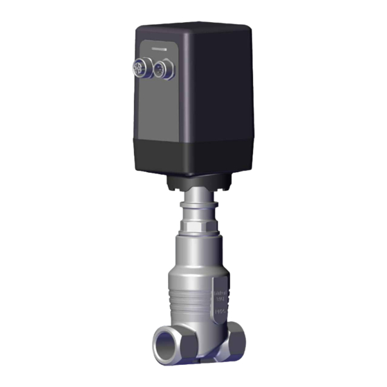
Type 3281 Product description PRODUCT DESCRIPTION Both variants have special functions that can be set using the Bürkert Communicator. Intended area of application The motor valve Type 3281 is designed to control the flow of liquid Structure and function and gaseous media. Only clean, liquid or gaseous media that do not attack the valve body and seal materials may be controlled. Stepper motor NOTE Damage to the valve body and seals due to unsuitable media. -
Page 8: Technical Data
Seat diameter Risk of injury due to malfunction if used outdoors. Electronic variant ▶ Do not use the device outdoors and keep it away from heat Type sources that could cause the permissible temperature range to be exceeded. 3281 X DN10 PTFE VA ▶ Protect the device from direct sunlight and humidity. G 3/8 PN 6 bar 24 V DC 20 W Tamb see manual... -
Page 9: Electrical Data
Type 3281 Technical data Electrical data Electrical data Positioner analog Positioner digital Process controller analog Process controller digital Connections Circular plug-in connector Circular plug-in connector Circular plug-in connector Circular plug-in connector M12x1, 8-pin M12x1, 5-pin M12x1, 8-pin and 5-pin M12x1, 5-pin and 8-pin Operating voltage 24 V DC ±10 %, residual ripple < 10 % 24 V DC ±10 %, residual ripple < 10 % Power consumption max. 12 W max. 12 W Standby power ca. 2 W ca. 2 W consumption Actuating time (0-100 %) ca. 2.5 s ca. 2.5 s Analogue input (set-point 0...20 mA, 4...20 mA, 0...5 V... -
Page 10: Mechanical Data
Type 3281 Technical data Mechanical data 6.5.1 Derating The maximum duty cycle of the valve depends on the maximum Materials ambient temperatures, the media temperature and the coil current Actuator cover P lastic parts black: PPS GF40, of the stepper motor. Plastic parts anthracite: PC GF10 Valve body Stainless steel VA The duty cycle does not mean the duty cycle of the device but the duty cycle of the stepper motor. Seal material PTFE Other materials in From the derating curve it can be read which maximum duty cycle the fluid sector Stainless steel VA is permissible at which maximum ambient temperature. Connections G1/2, RC1/2, NPT1/2 100 % Weight see data sheet 90 % Dimensions... -
Page 11: Installation
Type 3281 Installation INSTALLATION → Hold the device on the housing using an appropriate tool (e.g. open-end wrench) and screw into the pipeline. DANGER → Note the flow direction. Risk of injury due to high pressure in the system or device. T he digits on the valve body indicate the direction of flow (flow direction always under valve seat 2 → 1). ▶ Before working on the system or device, switch off the pressure and deaerate lines. Mounting the valve seat Risk of injury from electric shock. -
Page 12: Installing Valve Body
Type 3281 Installation Tightening torques for valve seat assembly: Valve seat size Tightening torques for coated seats [Nm] 4...10 20 ±3 Assembly tool → Screw the actuator to the valve body. The work steps required are described in chapter “7.4.2”. Installing valve body → Connect valve body to pipeline. Tool insert (depending on seat size) → Devices with welded connection: Weld the valve body into Valve seat the pipeline. To do this, observe chapter on Installing devices with welded connection. Fig. 4: Mounting the valve seat... -
Page 13: Turning Actuator
Type 3281 Installation → Place a suitable open-end wrench on the wrench flat of the DANGER body connection. Danger due to lubricant. Lubricant may contaminate the medium. There is a risk of explosion in oxygen applications. ▶ For specific applications use only approved lubricants (e.g. for oxygen applications or analysis applications). → Before re-installation, grease the thread of the body connection Open-end wrench (e.g. with Klüberpaste UH1 96-402 from Klüber). Wrench flat of the body connection NOTE Damage to the valve seat seal or seat contour. ▶ When installing the actuator, the valve must be in the open position. Fig. 5: Unscrewing the actuator →... -
Page 14: Installing The Device Electrically
Type 3281 Installation DANGER Risk of injury due to high pressure and escaping medium. If direction of rotation is incorrect, the body connection can detach. ▶ Rotate the actuator only in the specified direction of rotation. → Move the actuator into the required position by turning it Socket Circular plug clockwise (seen from above). M12, 5-pin M12, 8-pin Installing the device electrically Fig. 7: Name of the circular plug-in connector, analogue variant All electrical inputs and outputs of the device are not galvanically isolated to the supply voltage. - Page 15 Type 3281 Installation 7.6.1 Pin assignment of the pins for positioner CAN high CAN high 7.6.1.1 Analog variant, circular plug M12, 8-pin CAN low CAN low Pin assignment External circuit Supply + 24 V DC ±10%, max. Residual 7.6.2 Pin assignment of the pins for process ripple 10 % controller Supply GND 24 V DC GND 7.6.2.1 Analog variant, circular plug M12, 8-pin...
- Page 16 Type 3281 Installation 7.6.2.2 Analog variant, socket M12, 5-pin 7.6.2.4 Digital variant, socket M12, 5-pin Pin assignment External circuit Pin assignment External circuit Sensor supply + 24 V DC ±10 %, max. Residual Sensor supply + 24 V DC ±10 %, max. Residual ripple 10 % ripple 10 % Actual value 0...20 mA / 4...20 mA / 0...5 V Actual value input 0...20 mA / 4...20 mA / 0...5 V / input sensor + / 0...10 V sensor + 0...10 V / Frequency: 5-2000 Hz GND (bridge according to GND GND (bridge according to GND pin 3)
-
Page 17: Led Display
Type 3281 Installation LED display 7.7.2 Display elements NAMUR NE 107 The LED colours can be switched between standard and in line Colour Status Description with NAMUR NE 107, using the Bürkert Communicator software. code green permanently Diagnostics active 7.7.1 Display elements standard permanently Failure, error or fault Status Description white permanently on Normal operation green or 1 or 5 flashing Use to identify a device yellow permanently on Valve not fully open in the büS network... -
Page 18: Start-Up
Type 3281 Start-up START-UP MAINTENANCE WARNING WARNING Risk of injury if maintenance work is not carried out correctly. Risk of injury from improper operation. ▶ Maintenance may only be carried out by trained specialists ▶ The operating personnel must know and understand the using suitable tools. contents of the operating instructions. ▶ Secure the system against unintentional activation. ▶ Only adequately trained personnel may operate the system and the device. ▶ Ensure a controlled restart after maintenance is completed. ▶ Perform fluidic and electrical installation before start-up. Maintenance work The device has various functions that can be configured and The device operates maintenance-free under normal conditions. - Page 19 Type 3281 Maintenance LED is red The residual ripple Use power supply with Engine is Gears or engine Return device to the manu- and flashes of the supply smooth output voltage at humming blocked facturer for troubleshooting or LED is lit voltage is too high the required power unusually Valve is not Dirt between seal Install the strainer and After eliminating the error tight and valve seat return the device to the to clear the red flashing...
-
Page 20: Transport, Storage, Disposal
Type 3281 Transport, storage, disposal TRANSPORT, STORAGE, DISPOSAL NOTE Damage in transit due to inadequately protected devices. ▶ Protect the device against moisture and dirt in shock-resis- tant packaging during transportation. ▶ Observe permitted storage temperature. ▶ Protect pneumatic connections from damage with protective caps. Incorrect storage may damage the device. ▶ Store the device in a dry and dust-free location. ▶ Storage temperature –20...+70 °C. Damage to the environment caused by parts contaminated with media. - Page 22 www.burkert.com...
Need help?
Do you have a question about the 3281 and is the answer not in the manual?
Questions and answers