
Subscribe to Our Youtube Channel
Related Manuals for Burkert 3280


Summary of Contents for Burkert 3280
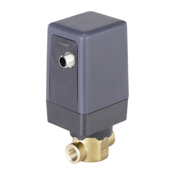
- Page 1 Type 3280, 3285 2-way motor valve 2-Wege-Motorventil Vanne motorisée 2 voies Operating Instructions Bedienungsanleitung Manuel d‘utilisation...
- Page 2 We reserve the right to make technical changes without notice. Technische Änderungen vorbehalten. Sous réserve de modifications techniques. © 2015-2019 Bürkert Werke GmbH & Co. KG Operating Instructions 1902/07_EU-ML_00810387 / Original DE...
-
Page 3: Table Of Contents
Type 3280, 3285 Motor valve Type 3280 and 3285 ontents Operating instructiOns ................................5 symbols ......................................5 1.1 Definition of terms .................................5 1.2 authOrizeD use .....................................6 Basic safety instructiOns ..............................7 general infOrmatiOn ................................8 contact address ..................................8 4.1 Warranty ......................................8 4.2 information on the internet ...............................8 4.3 prODuct DescriptiOn ................................9 intended use .....................................9 5.1 5.2 properties ....................................9 5.3... - Page 4 Pin assignment for the positioner ....................25 7.2.4 Pin assignment for process controller ...................26 Dip switch settings (analog version only) ......................27 7.3 7.3.1 Setting the DIP switch for Type 3280 and Type 3285 ..............28 7.4 accepting and saving sim card data (digital version only) ................32 7.5 leD display .....................................33 7.5.1 Display elements standard .......................33 7.5.2...
-
Page 5: Operating Instructions
Refers to information in these operating instructions or in other documentation. ▶ designates instructions for risk prevention. → Designates a procedure which you must carry out. 1.2 Definition of terms In these instructions the term "device" always refers to the 2-way motor valve Type 3280 and 3285. english... -
Page 6: Authorized Use
▶ Do not use the device outdoors. ▶ Do not expose the valve to direct sunlight. ▶ Use Type 3280 and 3285 only in conjunction with third-party devices and components recommended and authorized by Bürkert. ▶ The device must be used in compliance with the characteristics and commissioning and use conditions speci- fied in the contractual documents and in the user manual. -
Page 7: Basic Safety Instructions
To prevent injuries: ▶ Do not use Type 3280 and 3285 in potentially explosive areas. ▶ Do not subject the actuator housing and actuator cover to mechanical loading. ▶ Do not make any internal or external modifications on the device. Do not paint housing parts or screws. -
Page 8: General Information
You can also find information on the Internet under: www.burkert.com 4.2 Warranty The warranty is only valid if the motor valve Type 3280 and 3285 is used correctly in accordance with the specified operating conditions. 4.3 information on the internet The operating instructions and data sheets for Types 3280 and 3285 can be found on the Internet at: www.burkert.com... -
Page 9: Product Description
5.1 intended use The motor valve Type 3280 and 3285 is designed for controlling the flow rate of liquid and gaseous media. Only clean, liquid or gaseous medium, which does not react with the bodies and sealing materials, may be controlled. -
Page 10: Structure And Function
Elastomer seal Control cone Body Figure 1: Electromotive seat valve Type 3280 5.3.2 electromotive disk valve Type 3285 The disk valve consists of a stepper motor with gearbox which transfers the rotational torque to the actuator shaft via coupling. The actuator shaft has control/shut-off disc attached to it. A fixed disk with a mouth attached to the body is used as a valve seat. -
Page 11: Device Versions
5.4.1 electric control The motor valves 3280 and 3285 feature an electromotive actuator with an electric control. The device version is stated on the type label: G means on-off, 0 resp. H means control valve, C means positioner and D stands for process controller. - Page 12 Type 3280, 3285 Productdescription Both valve end positions are indicated by the LED status. Moreover, the position actual value recorded using the position measuring system is output via the M12 circular plug-in connector. It is possible to communicate with the device digitally via CANopen* or büS**.
- Page 13 Type 3280, 3285 Productdescription The process controller is integrated in a control circuit. The position set-point value of the valve is calculated from the process set-point value and the process actual value using the control parameters (PID controller). The process set-point value can be specified by an external signal.
-
Page 14: Technical Data
Technicaldata Technical DaTa 6.1 conformity The motor valve Type 3280 and 3285 is compliant with EU directives as stated in the EU Declaration of Conformity (if applicable). 6.2 standards The applied standards, which are used to demonstrate compliance with the EU Directives, are listed in the EU type test certificate and/or the EU Declaration of Conformity (if applicable). -
Page 15: Type Label
6.4 Type label Seat diameter Seal material Electronic valve version Body material Type 3280 X DN25 EPDM MS NPT 1/4 PN 6 bar Port connection, Pressure range 24 V DC Voltage, Max. power consumption Tamb see manual 2 6 8 6 1 1... -
Page 16: Electrical Data
2 W power consumption Actuating time Type 3280: approx. 2.5 s, Type 3280: approx. 2.5 s, for setting Type 3280: approx. 2.5 s, for setting (0...100 %) for setting “Valve actuating “Valve actuating speed normal”, see “Valve actuating speed normal”, see speed normal”, see chapter... - Page 17 Type 3280, 3285 Technicaldata standard positioner process controller electrical Digital Digital data On-Off control valve analog analog (fieldbus) (fieldbus) 60 Ω at 60 Ω at 60 Ω at 0...20 mA Input impedance 4...20 mA / 0...20 mA and and 4...20 mA / resolution 40 µA...
-
Page 18: Derating
Type 3280, 3285 Technicaldata 6.6.1 Derating The maximum duty cycle of the valve depends on the maximum ambient temperatures and the current required by the stepper motor. The duty cycle does not refer to the duty cycle of the device but to the duty cycle of the motor. This is not switched on unless the valve is to move. -
Page 19: Fluidic Data
Type 3280, 3285 Technicaldata type 3280 type 3285 seat ø 1...6 positioner and process controller seat ø 8...25 positioner and process controller seat ø 8, 10 standard type 3280 seat ø 1...6 > 6 bar, standard seat ø 8...10 p ositioner and process controller (only up to 50 °c) Normal operation Normal operation Low power function Low power function 5 10 15 20 25 30 35 40 45 50 55 60 65 15 20 25 30 35 40 45 50 55 60 65 5 10 max. ambient temperature [°c]... -
Page 20: Installation
→ Observe flow direction. The arrow on the body indicates the direction of flow. Type 3280: Flow direction below seat, is always closed against the medium flow; Type 3285: Flow direction above seat, is always closed with the medium flow. -
Page 21: Installation Area For Cartridge Body
Type 3280, 3285 Installation 7.1.1 installation area for cartridge body -0.2 +0.1 Ra1.6 36.5 -0.05 Ø 36 +0.05 0.05 Ø 33.8 +0.05 0.05 Rmax=10 0.02 11.75 (1.96) Figure 10: Installation area for cartridge body 7.1.2 installation of the motor valve with cartridge body Cartridge body Figure 11: Motor valve with cartridge body english... - Page 22 Type 3280, 3285 Installation → Check that the O-rings on the valve are clean. → Clean pipelines and flange connections. → Install a dirt filter upstream of the valve inlet (≤ 0.3 mm). If required, use a suitable lubricant (e.g. water) when installing the O-rings.
-
Page 23: Electrical Installation
Type 3280, 3285 Installation 7.2 electrical installation None of the electrical inputs and outputs of the device are galvanically isolated from the supply voltage. Danger! risk of injury due to electrical shock. ▶ Before working on the system or device, switch off and isolate the power supply to prevent reactivation of the device. -
Page 24: Pin Assignment For The On-Off Valve, Circular Connector M12, 8-Pole
Type 3280, 3285 Installation The threaded sleeve of the M12 circular connector is connected to the valve body. Connect the body to a suitable ground connection. To ensure electromagnetic compatibility (EMC), ensure that the cable is as short as possible and the cross-section is as large as possible. -
Page 25: Pin Assignment For The Positioner
Type 3280, 3285 Installation 7.2.3 pin assignment for the positioner 7.2.3.1 analog version, circular connector m12, 8-pole Wire colors* configuration external circuit white Supply + 24 V DC ±10 %, max. residual ripple 10 brown Supply GND 24 V DC GND green CAN low CAN low yellow CAN high CAN high grey CAN GND... -
Page 26: Pin Assignment For Process Controller
Type 3280, 3285 Installation 7.2.4 pin assignment for process controller 7.2.4.1 analog version, circular connector m12, 8-pole Wire colors* configuration external circuit white Supply + 24 V DC ±10 %, max. residual ripple 10 % brown Supply GND 24 V DC GND green CAN low CAN low yellow CAN high CAN high grey... -
Page 27: Dip Switch Settings (Analog Version Only)
Type 3280, 3285 Installation 7.2.4.3 Digital version, circular connector m12, 5-pole Wire colors configuration external circuit Shielding Supply + 24 V DC ±10 %, max. residual ripple 10 % black white CAN high CAN high blue CAN low CAN low * The indicated wire colors refer to the büS cables which are available as accessories. -
Page 28: Setting The Dip Switch For Type 3280 And Type 3285
→ Carefully loosen the 4 screws on the lower side of the actuator housing, Type 3280, or on the upper side of the actuator cover, Type 3285, using a suitable tool. Do not unscrew the screws completely, as they are designed not to fall out. - Page 29 Type 3280, 3285 Installation setting the Dip switch type 3280 Control electronics DIP switches Figure 17: Location of the DIP switch, Type 3280 setting the Dip switch type 3285 Control electronics DIP switches Figure 18: Location of the DIP switch for Type 3285 → DIP switch, set to “ON” or “OFF” depending on required function. To do this, carefully actuate the particular DIP switch using a suitable tool.
- Page 30 Type 3280, 3285 Installation Description of the function Dip posi- function for the function for the function for the function for the switches tion on-off control valve standard version positioner and pWm version process controller version (applies to analog version only) Normal oper- Normal operating Normal operating no function ating direction direction of the set- direction of the set-point of the set-point point value (e.g.
- Page 31 Carefully attach actuator cover. → Manually insert 4 screws into the designated holes on the lower side of the actuator housing, Type 3280, or on the upper side of the actuator cover, Type 3285, and turn them onto the first thread.
-
Page 32: Accepting And Saving Sim Card Data (Digital Version Only)
Type 3280, 3285 Installation 7.4 accepting and saving sim card data (digital version only) The optionally available SIM card can be used to save and transfer device-specific values and user settings to a different device. A SIM card which has just been inserted is checked for existing data during device restart. Where applicable, this data is accepted or overwritten: •... -
Page 33: Led Display
Type 3280, 3285 Installation 7.5 leD display With the aid of the positioner version and process controller version, it is possible to use the Bürkert-Communi- cator Software to toggle the LED colors between standard and NAMUR NE 107. 7.5.1 Display elements standard leD color status Display... - Page 34 Type 3280, 3285 Installation no color Valve without power supply or LED off english...
-
Page 35: Start-Up
▶ Only adequately trained personnel may operate the device. Before start-up, carry out fluid and electrical installation of the valve. Motor valve Type 3280 and 3285 has different functions which can be configured and parametrized via the DIP switches. 8.1 functions of the standard device The following basic functions can be activated or changed via the DIP switches. -
Page 36: Functions Of The Positioner And Process Controller Version
(max. medium pressure 3 bar, max. differential pressure 1 bar) 8.2 functions of the positioner and process controller version Motor valve Type 3280 and 3285 has different functions, which can be changed via the DIP switches and com- munications software. Functions for positioner and process controller: function... - Page 37 Type 3280, 3285 Start-up Parameterization büS or CANopen can be selected as a parameterization interface. See chapter interface “7.3” Communications In the case of the digital version, it is possible to communicate with the device via interface büS/CANopen (e.g. set-point/actual values) Functions for process controller only:...
-
Page 38: Setting Options
Type 3280, 3285 Start-up 8.3 setting options The Bürkert Communicator software enables communication with valves 3280 and 3285. The operating instructions for the Bürkert Communicator can be found at www.burkert.com. 8.3.1 setting options for running positioner and process controller INPUT/OUTPUT Selected standard signal Under this menu option, enter the signal used for the set-point value or actual value - Current 4...20 mA (for digital version only actual value) - Page 39 Type 3280, 3285 Start-up X.CONTROL Parameterization of the position controller, insensitivity range (dead band) of the position controller Input of the dead band in %, with regard to the scaled stroke/rotation angle range. This function ensures that the controller is only activated once a certain control difference has been achieved.
- Page 40 Type 3280, 3285 Start-up SAFEPOS when using the energy pack module (capacitive buffer module ID 773 440) Entry of the safety position To be able to approach a valve safety position in the event of a power failure, the valve must be energized via the capacitive buffer module.
- Page 41 Type 3280, 3285 Start-up The flow characteristic k = f(s) indicates the flow-rate of a valve, expressed by the k value depending on the position/angle s. It is specified by the design of the valve seat and the seat seal. In general two types of flow char- acteristics are implemented, the linear and the equal percentage.
-
Page 42: Setting Options For Running Process Controller
Type 3280, 3285 Start-up 8.3.2 setting options for running process controller PV.SCALE/SP.SCALE Scaling of the process controller The function can be used to specify the following settings: • Unit of the process actual value • Position of the decimal point • Values for the lower and upper process actual value •... - Page 43 Type 3280, 3285 Start-up • Amplification factor of the process controller. The amplification factor determines the P-component of the PID controller. • Reset time of the process controller. The reset time determines the I-component of the PID controller. • Derivative time of the process controller.
-
Page 44: Other Settings
Type 3280, 3285 Start-up 8.3.3 Other settings CAL INP Calibration of the position set-point value (4...20 mA; 0...20 mA; 0...5 V; 0...10 V) The set-point value input can be re-calibrated using this auxiliary function. Acceptance of the min. input signal (0 mA; 4 mA; 0 V): Create the minimum value of the input signal at the input and confirm it in the software. -
Page 45: Maintenance, Troubleshooting
The motor valve Type 3280 and 3285 is maintenance-free under normal conditions. 9.2 cleaning Use the normal cleaning agents to clean the Type 3280 and 3285. Use no alkaline cleansing agents, as these have a damaging effect on the materials used. 9.3... - Page 46 Type 3280, 3285 Maintenance,troubleshooting problem possible cause remedial action LED is not lit No power supply Check the electrical connections LED flashes The power supply collapses periodically - Select power supply with adequate power sporadically device software reboots each time Check cable for possible lose connections...
-
Page 47: Spare Parts
Type 3280, 3285 Spareparts spare parTs CauTion! risk of injury and/or damage by the use of incorrect parts. Incorrect accessories and unsuitable spare parts may cause injuries and damage the device and the surrounding area. ▶ Use original accessories and original spare parts from Bürkert only. 10.1 accessories Bürkert-Communicator software can be found on the Internet at www.burkert.com... -
Page 48: Packaging And Transport
Type 3280, 3285 Packagingandtransport packaging anD TranspOrT noTe! transport damage. Inadequately protected devices may be damaged during transportation. • Protect the device against moisture and dirt in shock-resistant packaging during transportation. • Prevent the temperature from exceeding or dropping below the permitted storage temperature. • Using protective caps, protect the electrical interfaces from damage. - Page 50 www.burkert.com...
Need help?
Do you have a question about the 3280 and is the answer not in the manual?
Questions and answers