Burkert 3232 Operating Instructions Manual
Manually operated diaphragm valves
Hide thumbs
Also See for 3232:
- Operating instructions manual (28 pages) ,
- Operating instructions manual (70 pages) ,
- Operating instructions manual (28 pages)
Table of Contents
Advertisement
Available languages
Available languages
Quick Links
Advertisement
Chapters
Table of Contents

Subscribe to Our Youtube Channel
Related Manuals for Burkert 3232


Summary of Contents for Burkert 3232
- Page 2 Type 3232, 3233, 3233 K, 3234, 3235, 3239 Manually operated diaphragm valves, Diameter DN 8 - DN 100 Handbetätigte Membranventile, Nennweiten DN 8 - DN 100 Vannes à membrane, commandé manuelle, Piston section nominale DN 8 - DN 100 Operating Instructions Bedienungsanleitung Manuel d‘utilisation...
- Page 3 We reserve the right to make technical changes without notice. Technische Änderungen vorbehalten. Sous réserve de modifications techniques. © 2011 Bürkert Werke GmbH Operating Instructions 1103/00_EU-ML_00809435 / Original DE...
-
Page 4: Table Of Contents
Type 3232, 3233, 3233 K, 3234, 3235, 3239 Contents 1. Operating instructiOns ..............4 8.2. Before installation ................13 8.3. Installation ..................15 1.1. Symbols ....................4 9. maintenance, cleaning ..............16 2. authOrized use ..................5 9.1. Safety instructions .................16 2.1. Restrictions ..................5 9.2. Maintenance work ................16 2.2. Predictable Misuse ................5 10. repairs ......................17 3. Basic safety instructiOns . -
Page 5: Operating Instructions
Type 3 232, 3233, 3233 K, 3234, 3235, 3239 Operating Instructions OperaTing insTrucTiOns Caution! The operating instructions describe the entire life cycle of the device. Warns of a possible danger! Keep these instructions in a location which is easily accessible to • Failure to observe this warning may result in a medium or minor every user and make these instructions available to every new owner injury. -
Page 6: Authorized Use
The Bürkert nearby equipment and the environment. resistance table of materials can be found on the Internet at: • The diaphragm valves of Types 3232, 3233, 3233 K, 3234, 3235 www.burkert.com and 3239 are designed for the control of contaminated, ultra-pure •... -
Page 7: Basic Safety Instructions
• The general rules of technology apply to application planning and operation of the device. Warning! danger of bursting from overpressure! The diaphragm valves Types 3232, 3233, 3233 K, 3234, 3235 and 3239 were developed with due consideration • Observe the specifications on the type label for max. control and medium pressure. -
Page 8: General Information
4.1. contact addresses 5.1. general description germany Type 3232, 3233, 3233 K, 3234, 3235 and 3239 is a manually con- trolled diaphragm valve with diaphragm seal. The valve is self-draining Bürkert Fluid Control Systems in appropriate installation position. Sales Center Christian-Bürkert-Str. 13-17 5.2. -
Page 9: Technical Data
Type 3 232, 3233, 3233 K, 3234, 3235, 3239 Technical data Technical daTa 6.2. Operating conditions Warning! 6.1. Type label danger of bursting from overpressure! Housing material If the device explodes, there is a risk of serious injury, chemical burns, scalding! Seal material • Do not exceed the maximum medium pressure. Observe specifi- cations on the type label! Orifice of the housing / •... - Page 10 Type 3232, 3233, 3233 K, 3234, 3235, 3239 Technical data medium temperature for diaphragms: maximum permitted medium pressure The values apply to housing made of: material temperature remarks • Plastic, EPDM -10 ... +130 °C Steam sterilization up to +150 °C • VA forged steel and VA precision casting, VA block material as well...
-
Page 11: General Technical Data
1127 (ISO 4200), DIN 11850 series 2 other connections on request Tab. 5: Maximum permitted medium pressure maximum permitted medium pressure media nominal width max. switchable medium pressure [bar] Flow media Type 3232; contaminated, aggressive, dn ultrapure, sterile media and media with higher handwheel and attachment gray cast iron anodized [mm] viscosity epdm / fkm ptfe installation position In any position, floor drain valve type 3235;... -
Page 12: Structure And Function
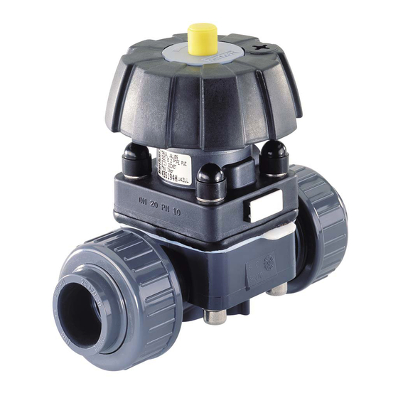
Tank bottom valve valve with Type 3235 welding flange Attachment Diaphragm housing Y-Valve Y-Valve Type 3239 housing Port connection Fig. 3: Example of the 2/2-way valve type 3232, 3233 and 3233 K Tab. 7: Structure. Types 3234, 3235 and 3239 english... -
Page 13: Function
Type 3 232, 3233, 3233 K, 3234, 3235, 3239 Installation 7.3. function insTallaTiOn The manual actuation of the handwheel transfers the force via a spindle 8.1. safety instructions and opens and closes the valve. Danger! 7.3.1. position indicator risk of injury from high pressure in the equipment! actuator size dn 4, dn 6, dn 8, dn 10, dn 65, dn 80 and dn 100 • Before loosening the lines and valves, turn off the pressure and When the valve is opened, a yellow mark is visible between the vent the lines. -
Page 14: Before Installation
Type 3232, 3233, 3233 K, 3234, 3235, 3239 Installation 8.2. Before installation 8.2.2. installation position T-valve Type 3234 For the installation of the T-valves into circular pipelines, we recommend • Before connecting the valve, ensure the pipelines are flush. the following installation positions: • The flow direction is optional. When media is When media is 8.2.1. installation position 2/2-way valve... - Page 15 Type 3 232, 3233, 3233 K, 3234, 3235, 3239 Installation 8.2.4. installation of the tank bottom valve Type 3235 For further information on containers and welding instructions, Grinding point please refer to the standard ASME VIII Division I. on tank It is recommended to weld the valve prior to the container Fig.
-
Page 16: Installation
Type 3232, 3233, 3233 K, 3234, 3235, 3239 Installation 8.2.5. preparatory work 8.3.1. devices with welded or glued housing → Clean pipelines (sealing material, swarf, etc.). → Support and align pipelines. note! devices with welded or glued housing: to prevent damage! Before welding or gluing the housing, the actuator and the diaphragm Before welding or gluing the housing, the actuator and the must be removed. -
Page 17: Maintenance, Cleaning
Type 3 232, 3233, 3233 K, 3234, 3235, 3239 Maintenance, Cleaning MainTenance, cleaning 8.3.2. Tightening torques for diaphragms actuator pps or stainless steel 9.1. safety instructions dn [mm] diaphragm diaphragm Danger! epdm / fkm ptfe risk of injury due to electrical shock! • Before reaching into the system , switch off the power supply and secure to prevent reactivation! • Observe applicable accident prevention and safety regulations for electrical equipment! Warning! risk of injury from improper maintenance! -
Page 18: Repairs
Type 3232, 3233, 3233 K, 3234, 3235, 3239 Repairs 9.2.2. Wearing parts of the diaphragm valve 10. repairs Parts which are subject to natural wear: 10.1. safety instructions • Seals • Diaphragm Danger! → If leaks occur, replace the particular wearing parts with an appro- priate spare part (see chapter (see Chapter 11). -
Page 19: Replacing The Diaphragm
Type 3 232, 3233, 3233 K, 3234, 3235, 3239 Repairs 10.2. replacing the diaphragm Manual actuator Danger! risk of injury from discharge of medium (acid, alkali, hot media)! 4 fastening screws It is dangerous to remove the device under pressure due to the sudden release of pressure or discharge of medium. • Before removing a device, switch off the pressure and vent the lines. Diaphragm •... - Page 20 Type 3232, 3233, 3233 K, 3234, 3235, 3239 Repairs → Detach or unscrew old diaphragm. If attachment is with a 10.2.1. Tightening torques for diaphragms bayonet catch, loosen the diaphragm by turning it 90° (see table „Tab. 10: Fastening types for diaphragm“). actuator pps or stainless steel → Turn handwheel all the way clockwise (CLOSED position).
-
Page 21: Spare Parts, Accessories
194 808 432 977 432 978 432 979 432 980 The following spare parts are available for the manually actuated diaphragm valves type 3232, 3233, 3233 K, 3234, 3235 and 3239: 20, 15* 432 984 432 985 432 986 432 987 •... -
Page 22: Handwheel Locking Device Option
Further information on spare parts can be found on the data 20, 15* 427 754 432 988 441 266 449 128 sheets for the piston-controlled diaphragm valves type 3232, 3233, 3233 K, 3234 and 3235. The data sheets can be found 25, 20* 427 755 432 995 441 267 441 271 on the Internet at: www.burkert.com... -
Page 23: Packaging And Transport
Type 3 232, 3233, 3233 K, 3234, 3235, 3239 Packaging and Transport 12. pacKaging and TranspOrT 14. dispOsal → Dispose of the device and packaging in an environmentally friendly note! manner. transport damages! Inadequately protected equipment may be damaged during note! transport. damage to the environment caused by device components • During transportation protect the device against wet and dirt in contaminated with media. - Page 24 Typ 3232, 3233, 3233 K, 3234, 3235, 3239 Inhaltsverzeichnis 1. die Bedienungsanleitung ............24 8.2. Vor dem Einbau ................33 8.3. Einbau ....................35 1.1. Darstellungsmittel ................24 9. Wartung, reinigung ................36 2. Bestimmungsgemässe VerWendung ........25 9.1. Sicherheitshinweise ...............36 2.1. Beschränkungen ................25 9.2. Wartungsarbeiten ................36 2.2. Vorhersehbarer Fehlgebrauch .............25 10. instandhaltung ................... 37 3. grundlegende sicherheitshinWeise .
-
Page 25: Die Bedienungsanleitung
Typ 3 232, 3233, 3233 K, 3234, 3235, 3239 Die Bedienungsanleitung die BedienungsanleiTung VorsiCht! Die Bedienungsanleitung beschreibt den gesamten Lebenszyklus Warnt vor einer möglichen gefährdung! des Gerätes. Bewahren Sie diese Anleitung so auf, dass sie für jeden • Nichtbeachtung kann mittelschwere oder leichte Verletzungen Benutzer gut zugänglich ist und jedem neuen Eigentümer des Gerätes zur Folge haben. -
Page 26: Bestimmungsgemässe Verwendung
• Das Gehäuse nicht mechanisch belasten (z. B. durch Ablage von • Die Membranventile des Typs 3232, 3233, 3233 K, 3234, 3235 Gegenständen oder als Trittstufe). und 3239 sind für die Steuerung von verschmutzten, hochreinen • Keine äußerlichen Veränderungen an den Gerätegehäusen vor- oder sterilen Medien, sowie für abrasive oder aggressive Medien... -
Page 27: Grundlegende Sicherheitshinweise
• Für die Einsatzplanung und den Betrieb des Gerätes müssen die Warnung! allgemeinen Regeln der Technik eingehalten werden. Berstgefahr bei Überdruck! Die Membranventile Typ 3232, 3233, 3233 K, 3234, 3235, • Die Angaben auf dem Typenschild, für max. Mediumsdruck 3239 wurden unter Einbeziehung der anerkannten sicherheits- einhalten. -
Page 28: Allgemeine Hinweise
4.1. Kontaktadressen 5.1. allgemeine Beschreibung Deutschland Der Typ 3232, 3233, 3233 K, 3234, 3235 und 3239 ist ein handge- steuertes Membranventil mit Membranabdichtung. Das Ventil ist bei Bürkert Fluid Control Systems entsprechender Einbaulage selbstentleerend. Sales Center Christian-Bürkert-Str. 13-17 5.2. -
Page 29: Technische Daten
Typ 3 232, 3233, 3233 K, 3234, 3235, 3239 Technische Daten Technische daTen 6.2. Betriebsbedingungen Warnung! 6.1. Typenschild Berstgefahr bei Überdruck! Gehäusewerkstoff Beim Bersten des Gerätes drohen schwere Verletzung, Verätzung, Verbrühung! Dichtwerkstoff • Den maximalen Mediumsdruck nicht überschreiten. Angaben auf dem Typenschild beachten! Nennweite des Gehäuses / • Zulässige Umgebungs- und Mediumstemperatur einhalten. Antriebsgröße 6.2.1. zulässige Temperaturen umgebungstemperatur für antriebe:... - Page 30 Typ 3232, 3233, 3233 K, 3234, 3235, 3239 Technische Daten mediumstemperatur für membranen: maximal zulässiger mediumsdruck Die Werte sind gültig für Gehäuse aus: Werkstoff temperatur Bemerkungen • Kunststoff, EPDM -10 ... +130 °C Dampfsterilisation bis +150 °C • VA-Schmiedestahl und VA-Feinguss, sowie VA-Rohrumformgehäuse PTFE mit Muffe, DIN-Vorschweißflansch und Schweißanschluss nach EN ISO 1127 / ISO 4200 Trocken bis +150 °C, sonst nur...
-
Page 31: Allgemeine Technische Daten
Schweißanschluss nach DIN EN 1127 (ISO 4200), DIN 11850 R2 andere Anschlüsse auf Anfrage Tab. 5: Maximal zulässiger Mediumsdruck medien maximal zulässiger mediumsdruck Durchflussmedien Typ 3232; verschmutzte, aggressive, nennweite dn max. schaltbarer mediumsdruck [bar] hochreine, sterile Medien und Medien mit [mm] höherer Viskosität handrad und aufsatz grauguss eloxiert epdm / fkm ptfe einbaulage beliebig, Bodenablassventil Typ 3235;... -
Page 32: Aufbau Und Funktion
Handrad mit Stellungsanzeige (siehe Kapitel 7.3.1) Bodenablass- Bodenablass- ventil gehäuse mit Typ 3235 Schweißflansch Aufsatz Membrangehäuse Y-Ventil Y-Ventilgehäuse Typ 3239 Leitungsanschluss Bild 3: Beispiel des 2/2-Wege Ventils Typ 3232, 3233 und Tab. 7: Aufbau. Typen 3234, 3235 und 3239 3233 K deutsch... -
Page 33: Funktion
Typ 3 232, 3233, 3233 K, 3234, 3235, 3239 Montage 7.3. funktion MOnTage Durch die manuelle Betätigung des Handrads wird die Kraft über eine 8.1. sicherheitshinweise Spindel übertragen und das Ventil geöffnet oder geschlossen. gefahr! 7.3.1. stellungsanzeige Verletzungsgefahr durch hohen druck in der anlage! antriebsgröße dn 4, dn 6, dn 8, dn 10, dn 65, dn 80 und dn 100 • Vor dem Lösen von Leitungen oder Ventilen den Druck abschal- Mit Öffnen des Ventils wird eine gelbe Markierung zwischen dem ten und Leitungen entlüften. -
Page 34: Vor Dem Einbau
Typ 3232, 3233, 3233 K, 3234, 3235, 3239 Montage 8.2. Vor dem einbau 8.2.2. einbaulage T-Ventile Typ 3234 Für den Einbau der T-Ventile in Ringleitungen werden folgende Ein- • Vor dem Anschluss des Ventils auf fluchtende Rohrleitungen achten. baulagen empfohlen: • Durchflussrichtung ist beliebig. Bei Zuführung eines Bei Entnahme von 8.2.1. einbaulage 2/2-Wege Ventile... - Page 35 Typ 3 232, 3233, 3233 K, 3234, 3235, 3239 Montage 8.2.4. einbau des Bodenablassventils Typ 3235 Für Informationen über Behälter und Schweißanweisungen, Zu schleifende Stelle beziehen Sie sich auf die Norm ASME VIII Division I. am Tank Es empfiehlt sich das Ventil zu schweißen bevor der Behälter Bild 7: Zu schleifende Stelle am Tank aufgebaut wird.
-
Page 36: Einbau
Typ 3232, 3233, 3233 K, 3234, 3235, 3239 Montage 8.2.5. Vorbereitende arbeiten 8.3.1. geräte mit schweiß- oder Klebegehäuse → Rohrleitungen von Verunreinigungen säubern (Dichtungsmaterial, Metallspäne etc.). hinWeis! → Rohrleitungen abstützen und ausrichten. zur Vermeidung von schäden! Geräte mit Schweiß- oder Klebegehäuse: Vor dem Einschweißen oder Verkleben des Gehäuses muss der Antrieb und die Membran demontiert werden. -
Page 37: Wartung, Reinigung
Typ 3 232, 3233, 3233 K, 3234, 3235, 3239 Wartung, Reinigung WarTung, reinigung 8.3.2. anzugsmomente für Membranen antrieb pps oder edelstahl 9.1. sicherheitshinweise dn [mm] membran membran gefahr! epdm / fkm ptfe Verletzungsgefahr durch stromschlag! • Vor Eingriffen in das Gerät oder die Anlage, Spannung abschal- ten und vor Wiedereinschalten sichern! • Die geltenden Unfallverhütungs- und Sicherheitsbestimmungen für elektrische Geräte beachten! Warnung! Verletzungsgefahr bei unsachgemäßen Wartungsarbeiten! -
Page 38: Instandhaltung
Typ 3232, 3233, 3233 K, 3234, 3235, 3239 Instandhaltung 9.2.2. Verschleißteile des Membranventils 10. insTandhalTung Teile die einer natürlichen Abnutzung unterliegen sind: 10.1. sicherheitshinweise • Dichtungen • Membran gefahr! → Bei Undichtheiten das jeweilige Verschleißteile gegen ein entspre- chendes Ersatzteil austauschen (siehe Kapitel 11). Verletzungsgefahr durch hohen druck in der anlage! • Vor dem Lösen von Leitungen und Ventilen den Druck abschalten Eine ausgebeulte PTFE-Membran, kann zur Reduzierung und Leitungen entlüften. -
Page 39: Austausch Der Membran
Typ 3 232, 3233, 3233 K, 3234, 3235, 3239 Instandhaltung 10.2. austausch der Membran Handantrieb gefahr! Verletzungsgefahr durch mediumsaustritt (säure, lauge, 4 Befestigungsmuttern heiße medien)! Der Ausbau des Gerätes unter Druck ist wegen plötzlicher Druck- entladung oder Mediumsaustritt gefährlich. • Vor dem Ausbau den Druck abschalten und Leitungen entlüften. Membran • Leitungen vollständig entleeren. Gehäuse Befestigungsarten Befestigungsarten für membranen... - Page 40 Typ 3232, 3233, 3233 K, 3234, 3235, 3239 Instandhaltung → Alte Membran ausknöpfen oder ausschrauben. Bei Befestigung 10.2.1. anzugsmomente für Membranen mit Bajonettverschluss die Membran durch Drehen um 90° lösen (siehe Tabelle „Tab. 10: Befestigungsarten für Membranen“). antrieb pps oder edelstahl → Handrad im Uhrzeigersinn bis zum Anschlag drehen (Stellung dn [mm] membran membran ZU).
-
Page 41: Ersatzteile, Zubehör
194 809 194 808 194 808 432 977 432 978 432 979 432 980 Als Ersatzteile für die handbetätigten Membranventile Typ 3232, 3233, 3233 K, 3234, 3235 und 3239 sind erhältlich: 20, 15* 432 984 432 985 432 986 432 987 •... -
Page 42: Option Sicherung Handrad
20, 15* 427 754 432 988 441 266 449 128 den Datenblättern für die kolbengesteuerte Membranventile Typ 3232, 3233, 3233 K, 3234 und 3235. Die Datenblätter 25, 20* 427 755 432 995 441 267 441 271 finden Sie im Internet unter: www.buerkert.de... -
Page 43: Verpackung, Transport
Typ 3 232, 3233, 3233 K, 3234, 3235, 3239 Verpackung, Transport 12. VerpacKung, TranspOrT 14. enTsOrgung → Entsorgen Sie das Gerät und die Verpackung umweltgerecht. hinWeis! transportschäden! hinWeis! Unzureichend geschützte Geräte können durch den Transport umweltschäden durch von medien kontaminierte geräteteile. beschädigt werden. • Geltende Entsorgungsvorschriften und Umweltbestimmungen • Gerät vor Nässe und Schmutz geschützt in einer stoßfesten einhalten. - Page 44 Type 3232, 3233, 3233 K, 3234, 3235, 3239 Sommaire 1. les instructiOns de serVice ............. 44 8.2. Avant le montage ................53 8.3. Montage ...................55 1.1. Symboles..................44 9. maintenance, nettOyage ..............56 2. utilisatiOn cOnfOrme............... 45 9.1. Consignes de sécurité ..............56 2.1. Limitations ..................45 9.2. Travaux d’entretien .................56 2.2. Mauvaise utilisation prévisible .............45 10. maintenance ...................
-
Page 45: Les Instructions De Service
Type 3 232, 3233, 3233 K, 3234, 3235, 3239 Les instructions de service les insTrucTiOns de attention ! serVice met en garde contre un risque possible ! Les instructions de service décrivent le cycle de vie complet de l’ap- • Le non-respect peut entraîner des blessures légères ou de pareil. Conservez ces instructions de sorte qu’elles soient accessibles moyenne gravité. -
Page 46: Utilisation Conforme
Bürkert des différents matériaux sur Internet sous: l’environnement. www.buerkert.fr. • Les vannes à membre des types 3232, 3233, 3233 K, 3234, 3235 • Ne soumettez pas le corps à des contraintes mécaniques (par ex. et 3239 sont prévues pour la commande de fluides encrassés, de grande pureté... -
Page 47: Consignes De Sécurité Fondamentales
! risque d’éclatement en cas de surpression ! Les vannes à membrane de type 3232, 3233, 3233 K, 3234, 3235, 3239 ont été développées dans le respect des règles • Respectez les indications figurant sur la plaque signalétique relatives à la pression de commande et du fluide max. -
Page 48: Indications Générales
5.1. description générale allemagne Les types 3232, 3233, 3233 K, 3234, 3235 et 3239 sont des vannes à membrane à commande manuelle avec un joint d’étanchéité de Bürkert Fluid Control Systems membrane. La vanne se vide automatiquement lorsque sa position de Sales Center montage est correcte. -
Page 49: Caractéristiques Techniques
Type 3 232, 3233, 3233 K, 3234, 3235, 3239 Caractéristiques techniques caracTérisTiques Techniques 6.2. conditions d’exploitation aVertissement ! 6.1. plaque signalétique risque d’éclatement en cas de surpression ! Matériau du boîtier Risque de blessures, de brûlures par acide, d’échaudures en cas d’éclatement de l’appareil ! Matériau du joint • Ne dépassez pas la pression de fluide maximale. Respectez les indications sur la plaque signalétique ! Diamètre nominal du corps •... - Page 50 Type 3232, 3233, 3233 K, 3234, 3235, 3239 Caractéristiques techniques température du fluide pour les membranes : pression de fluide maximale admissible Les valeurs sont valables pour des boîtiers en matériau température remarques • Plastique, EPDM Stérilisation à la vapeur jusqu’à • Acier forgé VA et coulée de précision VA, bloc VA ainsi que boîtier de -10 ...
-
Page 51: Caractéristiques Techniques Générales
Volant et chapeau en fonte grise anodisée Fluides de débit Type 3232 ; fluides encrassés, agressifs, très [mm] purs, stériles et fluides à haute viscosité epdm / fkm ptfe position de montage au choix, vanne de fond de cuve type 3235 ;... -
Page 52: Structure Et Mode De Fonctionnement
Chapeau Vanne Y Type Corps de Boîtier à membrane 3239 vanne T Raccord de conduite Tab. 7 : Structure. Types 3234, 3235 et 3239 Fig. 3 : Exemple de la vanne 2/2 voies types 3232, 3233 et 3233 K français... -
Page 53: Fonction
Type 3 232, 3233, 3233 K, 3234, 3235, 3239 Montage 7.3. fonction MOnTage L’actionnement manuel du volant transmet la force via une broche, 8.1. consignes de sécurité entraînant l’ouverture ou la fermeture de la vanne. Danger ! 7.3.1. indicateur de position risque de blessures dû à la présence de haute pression dans tailles d’actionneur dn 4, dn 6, dn 8, dn 10, dn 65, dn 80 et l’installation ! dn 100 • Avant de desserrer les conduites et les vannes, coupez la pres- A l’ouverture de la vanne, une marque jaune apparaît entre le chapeau sion et purgez l’air des conduites. -
Page 54: Avant Le Montage
Type 3232, 3233, 3233 K, 3234, 3235, 3239 Montage 8.2. avant le montage 8.2.2. position de montage vanne T 3234 Les positions de montage suivantes sont recommandées pour les • Veillez à ce que les tuyauteries soient correctement alignées. vannes T dans des conduites en boucle : • Le sens de débit est indifférent. - Page 55 Type 3 232, 3233, 3233 K, 3234, 3235, 3239 Montage 8.2.4. Montage de la vanne de fond de cuve type 3235 Veuillez vous référer à la norme ASME VIII, section I pour obtenir Endroit à meuler sur des informations sur les cuves et les instructions de soudage. la cuve Il est recommandé de souder la vanne avant d’installer la cuve. Fig.
-
Page 56: Montage
Type 3232, 3233, 3233 K, 3234, 3235, 3239 Montage 8.2.5. Travaux préparatoires 8.3.1. appareils avec boîtier soudé ou collé → Nettoyez les tuyauteries (matériau d’étanchéité, copeaux de remarque ! métal, etc.). pour éviter les dommages ! → Soutenez et alignez les tuyauteries. Avant le soudage ou le collage du boîtier, il est nécessaire de appareils avec boîtier soudé ou collé : démonter l’actionneur et la membrane. -
Page 57: Maintenance, Nettoyage
Type 3 232, 3233, 3233 K, 3234, 3235, 3239 Maintenance, nettoyage MainTenance, neTTOyage 8.3.2. couples de serrage pour membranes actionneur pps ou acier inoxydable 9.1. consignes de sécurité dn [mm] membrane membrane Danger ! epdm / fkm ptfe risque de choc électrique ! • Avant d’intervenir dans le système , coupez la tension et empê- chez toute remise sous tension par inadvertance ! •... -
Page 58: Maintenance
Type 3232, 3233, 3233 K, 3234, 3235, 3239 Maintenance 9.2.2. pièces d’usure de la vanne à 10. MainTenance membrane 10.1. consignes de sécurité Les pièces soumises à une usure naturelle sont les suivantes : • Joints et Membrane Danger ! → En cas de fuites, remplacez la pièce d’usure concernée par une pièce de rechange correspondante (voir Chapitre 11). -
Page 59: Remplacement De La Membrane
Type 3 232, 3233, 3233 K, 3234, 3235, 3239 Maintenance 10.2. remplacement de la membrane Actionneur manuel Danger ! risque de blessures en cas d’échappement de fluide (acide, 4 vis de fixation soude, fluides brûlants) ! Le démontage de l’appareil sous pression est dangereux du fait de la décharge de pression ou de la sortie de fluide soudaine. • Avant le démontage, coupez la pression et purgez l’air des conduites. Membrane •... - Page 60 Type 3232, 3233, 3233 K, 3234, 3235, 3239 Maintenance → Déclipser ou dévisser l’ancienne membrane. En cas de 10.2.1. couples de serrage pour membranes fixation avec fermeture à baïonnette, desserrer la membrane en la tournant de 90° (voir „Tab. 10 : Types de fixation pour actionneur pps ou acier inoxydable membranes“). dn [mm] membrane membrane →...
-
Page 61: Pièces De Rechange, Accessoires
• Utilisez uniquement des accessoires ainsi que des pièces de rechange d’origine de la société Bürkert. 432 977 432 978 432 979 432 980 Disponibles en tant que pièces de rechange pour les types 3232, 20, 15* 432 984 432 985 432 986 432 987... -
Page 62: Option Verrouillage Du Volant
Type 3232, 3233, 3233 K, 3234, 3235, 3239 Pièces de rechange, Accessoires Volant et chapeau en acier Volant et chapeau en acier 677 669 677 689 677 679 inoxydable inoxydable (pour vanne en 677 670 677 690 677 680 dn t ou de fond de cuve) [mm] 677 671 677 691 677 681 membrane membrane membrane membrane 650 082 650 083 650 087... -
Page 63: Emballage, Transport
Type 3 232, 3233, 3233 K, 3234, 3235, 3239 Emballage, transport 12. eMBallage, TranspOrT 14. éliMinaTiOn → Éliminez l’appareil et l’emballage dans le respect de l’environnement. remarque ! dommages dus au transport ! remarque ! Les appareils insuffisamment protégés peuvent être endommagés dommages à l’environnement causés par des pièces d’ap- pendant le transport. pareil contaminées par des fluides. • Transportez l’appareil à l’abri de l’humidité et des impuretés et •... - Page 65 www.burkert.com...
Need help?
Do you have a question about the 3232 and is the answer not in the manual?
Questions and answers