Burkert 3233 Operating Instructions Manual
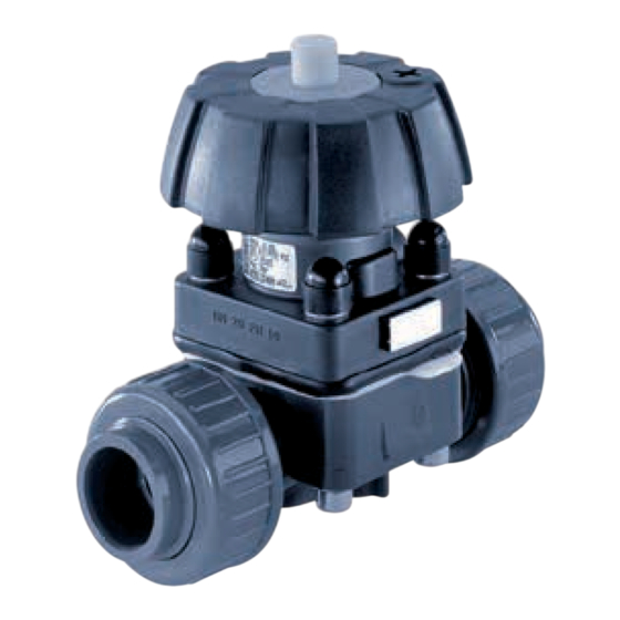
Manually operated diaphragm valves
Hide thumbs
Also See for 3233:
- Instruction manual (30 pages) ,
- Operating instructions manual (70 pages) ,
- Operating instructions manual (28 pages)
Table of Contents
Advertisement
Quick Links
Download this manual
See also:
Instruction Manual
Advertisement
Table of Contents

Subscribe to Our Youtube Channel
Related Manuals for Burkert 3233


Summary of Contents for Burkert 3233
- Page 1 Type 3232, 3233, 3233 K, 3234, 3235, 3239 Manually operated diaphragm valves, Diameter DN8 - DN100 Handbetätigte Membranventile, Nennweiten DN8 - DN100 Vannes à membrane, commandé manuelle, Piston section nominale DN8 - DN100 Operating Instructions Bedienungsanleitung Manuel d‘utilisation...
- Page 2 We reserve the right to make technical changes without notice. Technische Änderungen vorbehalten. Sous réserve de modifications techniques. © Bürkert Werke GmbH & Co. KG, 20 - 2017 Operating Instructions 1706/0 _EU-EN_008 / Original DE...
-
Page 3: Table Of Contents
Type 3232, 3233, 3233 K, 3234, 3235, 3239 Contents 1 Operating instructiOns ..............4 Function ..................15 Definition of the term “device” ..........4 8 installatiOn .................... 15 Symbols ..................4 Before installation ..............15 2 authOrized use ..................5 Installation .................18 9 maintenance, cleaning ..............20 3 Basic safety instructiOns . -
Page 4: Operating Instructions
▶ Failure to observe this warning may result in a medium or minor In these instructions, the term “device” always refers to the Type injury. 3232, 3233, 3233 K, 3234, 3235 and 3239. note! Warns of damage to property. Indicates important additional information, tips and recommendations. -
Page 5: Authorized Use
These safety instructions do not make allowance for any ▶ The diaphragm valves of Types 3232, 3233, 3233 K, 3234, 3235 • Contingencies and events which may arise during the installation, and 3239 are designed for the control of contaminated, ultra-pure operation and maintenance of the devices. -
Page 6: General Information
▶ Do not make any external modifications to the device body. Do with the specified application conditions. not paint the body parts or screws. 4.3 information on the internet The operating instructions and data sheets for Types 3232, 3233, 3233 K, 3234, 3235, 3239 can be found on the Internet at: www.burkert.com english... -
Page 7: System Description
6.1 conformity Type 3232, 3233, 3233 K, 3234, 3235 and 3239 is a manually con- Type 3232, 3233, 3233 K, 3234, 3235, 3239 conforms with the EU trolled diaphragm valve with diaphragm seal. The valve is self-draining Directives according to the EU Declaration of Conformity. - Page 8 Type 3232, 3233, 3233 K, 3234, 3235, 3239 Technical data 6.3.1 allowable temperatures material temperature remarks ambient temperature for actuators: Advanced -5...+143 °C Steam sterilisation up to +150 °C / 60 min PTFE (EU) material temperature Advanced -10...+90 °C Up to 130 °C (briefly up to 150 °C)
-
Page 9: Description Of The Type Label
Type 3232, 3233, 3233 K, 3234, 3235, 3239 Technical data maximum permitted medium pressure maximum permitted medium pressure The values apply to body made of: Orifice max. switchable medium pressure [bar] • plastic, (diaphragm handwheel and bonnet stainless steel size) • stainless steel: block material, forged, casted and tube valve body. epdm/fKm ptfe/advanced ptfe/ dn... -
Page 10: Labeling Of The Forged Body
Type 3232, 3233, 3233 K, 3234, 3235, 3239 Technical data 6.5 labeling of the forged body 6.6 labeling of the tube valve body (Vp) Batch number/ Production/order XX F manufacturing code number (F-part) Material Company logo Heat Company logo Serial number XXXXXXXX/XXX Material 1.4435/316L(VS) XXXX PN16/CWP150 XXXXXX Self-drain angle 1.4435... -
Page 11: General Technical Data
Type 3232, 3233, 3233 K, 3234, 3235, 3239 Technical data 6.7 general technical data 6.8 flow values materials 6.8.1 flow values for forged bodies Body Tube valve body (VA, VP), Precision casting (VG), Forged steel (VS), PP, Kvs values [m /h] for forged bodies PVC, PVDF diaph- Orifice actua- seal asme Bs... - Page 12 Type 3232, 3233, 3233 K, 3234, 3235, 3239 Technical data 6.8.2 flow values for cast bodies and 25 / 1" F/80 EPDM 20.0 18.0 15.5 16.0 plastic bodies PTFE 17.0 16.0 14.5 14.8 H/125 EPDM 34.0 Kvs value [m /h] for cast bodies Vg and plastic bodies pd. pp. pV PTFE 34.0 diaphragm Orifice seal cast body plastic body...
- Page 13 Type 3232, 3233, 3233 K, 3234, 3235, 3239 Technical data 6.8.3 flow values for tube valve body 25 / 1" F/80 EPDM 19.1 PTFE 15.6 Kvs values [m /h] for tube valve body Vp (ihu2) tVB3g F/80 EPDM 20.0 diaphragm Orifice actuator seal asme size connection size material PTFE 15.8 (dn) G/100 EPDM 36.0...
-
Page 14: Structure And Function
Tank bottom valve valve with Type 3235 welding flange Attachment Diaphragm body Y-Valve Y-Valve body Type 3239 Port connection Fig. 5: Example of the 2/2-way valve type 3232, 3233 and 3233 K Tab. 9: Structure. Types 3234, 3235 and 3239 english... -
Page 15: Function
Type 3232, 3233, 3233 K, 3234, 3235, 3239 Installation 7.3 function insTallaTiOn The manual actuation of the handwheel transfers the force via a spindle Danger! and opens and closes the valve. risk of injury from high pressure in the equipment. ▶ Before loosening the lines and valves, turn off the pressure and 7.3.1 position indicator... - Page 16 Type 3232, 3233, 3233 K, 3234, 3235, 3239 Installation 8.1.1 installation position general installation for self-drainage of the body Angle α: 10° to 40° α Inclination to the line axis 1° – 5° It is the responsibility of the installer and operator to ensure self-drainage. installation for leakage detection Fig. 6:...
- Page 17 Type 3232, 3233, 3233 K, 3234, 3235, 3239 Installation 8.1.3 installation position T-valve Type 3234 8.1.5 installation of the tank bottom valve Type 3235 For the installation of the T-valves into circular pipelines, we recommend the following installation positions: For further information on containers and welding instructions, When media is supplied: When media is removed: please refer to the standard ASME VIII Division I.
-
Page 18: Installation
Type 3232, 3233, 3233 K, 3234, 3235, 3239 Installation 8.1.6 preparatory work → Clean pipelines (sealing material, swarf, etc.). → Support and align pipelines. Grinding point on tank devices with welded or glued body: Before welding or gluing the body, the actuator and the diaphragm must be removed. - Page 19 Type 3232, 3233, 3233 K, 3234, 3235, 3239 Installation → Cross-loosen fastening screws and remove actuator with dia- 8.2.2 Tightening torques for diaphragms phragm from the body. → actuator pps or stainless steel Weld or glue body in the pipeline. Orifice → diaphragm diaphragm After welding or gluing in the body, smooth the body surface (if...
-
Page 20: Maintenance, Cleaning
Type 3232, 3233, 3233 K, 3234, 3235, 3239 Maintenance, Cleaning → mainTenance, cleaning If leaks occur, replace the particular wearing parts with an appro- priate spare part (see chapter “11”). Danger! A bulging PTFE diaphragm may reduce the flow-rate. risk of injury due to electrical shock. ▶ Before reaching into the system , switch off the power supply and secure to prevent reactivation. -
Page 21: Repairs
Type 3232, 3233, 3233 K, 3234, 3235, 3239 Repairs repairs 10.1 replacing the diaphragm Danger! Danger! risk of injury from discharge of medium (acid, alkali, hot media). risk of injury from high pressure in the equipment. ▶ Before loosening the lines and valves, turn off the pressure and It is dangerous to remove the device under pressure due to the vent the lines. - Page 22 Type 3232, 3233, 3233 K, 3234, 3235, 3239 Repairs → Align diaphragm. note marker for direction of flow! Manual → actuator Place actuator back on the body. → Lightly cross-tighten the fastening screws until the diaphragm is 4 fastening between the body and actuator. screws do not tighten screws yet.
-
Page 23: Spare Parts, Accessories
▶ Use only original accessories and original spare parts from Bürkert. The following spare parts are available for the manually actuated diaphragm valves type 3232, 3233, 3233 K, 3234, 3235 and 3239: • Manual actuator complete, • Diaphragm. Tab. 13: Tightening torques for diaphragms, actuator PPS or... -
Page 24: 11.1 Order Table
Type 3232, 3233, 3233 K, 3234, 3235, 3239 Spare parts, Accessories 11.1 Order table handwheel and bonnet handwheel and bonnet stainless steel stainless steel (for t or tank bottom valve) 11.1.1 Order tables for manual actuators Orifice diaphragm diaphragm diaphragm diaphragm (types 3232, 3233 and 3233 K) (diaphragm epdm, fKm ptfe/ epdm, fKm ptfe/ size) advanced advanced handwheel and handwheel pps, bonnet [mm] ptfe/ ptfe/... - Page 25 ** Identification on the diaphragm Further information on spare parts can be found on the data sheets for the piston-controlled diaphragm valves type 3232, 3233, 3233 K, 3234 and 3235. The data sheets can be found on the Internet at: www.burkert.com.
-
Page 26: 11.2 Handwheel Locking Device Option
Type 3232, 3233, 3233 K, 3234, 3235, 3239 Transport, Storage, Disposal 11.2 handwheel locking device option TranspOrT, sTOrage, DispOsal The handwheel locking device option (from actuator size DN15 to DN50) prevents unintentional or unauthorized operation of the valve. note! Handwheel can be locked in 12 detent positions per revolution (30°... - Page 28 www.burkert.com...
Need help?
Do you have a question about the 3233 and is the answer not in the manual?
Questions and answers