Burkert 2012 Operating Instructions Manual
Globe valve, pneumatically operated
Hide thumbs
Also See for 2012:
- Operating instructions manual (26 pages) ,
- Operating instructions manual (57 pages)
Table of Contents
Advertisement
Quick Links
Type 2012
Globe valve, pneumatically operated
Actuator sizes 175 mm and 225 mm, Nominal diameter DN65 to DN100
Kolbengesteuertes Geradsitzventil
Antriebsgrößen 175 mm und 225 mm, Nennweiten DN65 bis DN100
Vanne à siège droit commandée par piston
Tailles d'actionneur 175 mm et 225 mm, Diamètre nominal DN65 á DN100
Operating Instructions
Bedienungsanleitung
Manuel d'utilisation
Advertisement
Table of Contents

Subscribe to Our Youtube Channel
Related Manuals for Burkert 2012


Summary of Contents for Burkert 2012
- Page 1 Type 2012 Globe valve, pneumatically operated Actuator sizes 175 mm and 225 mm, Nominal diameter DN65 to DN100 Kolbengesteuertes Geradsitzventil Antriebsgrößen 175 mm und 225 mm, Nennweiten DN65 bis DN100 Vanne à siège droit commandée par piston Tailles d'actionneur 175 mm et 225 mm, Diamètre nominal DN65 á DN100...
- Page 2 We reserve the right to make technical changes without notice. Technische Änderungen vorbehalten. Sous réserve de modifications techniques. © Bürkert Werke GmbH & Co. KG, 2000 - 2022 Operating Instructions 2211/17_EN-DE-FR_00804396 / Original DE...
-
Page 3: Table Of Contents
Type 2012 Contents 8.2 Before installation ............12 OPERATING INSTRUCTIONS ..........4 8.3 Remove actuator from the valve body Symbols ............... 4 (welded connection) ..........12 1.2 Definition of the term "device" ........4 8.4 Installing valve body ..........13 INTENDED USE ..............5 8.5 Install actuator (welded connection) ....... 13 8.6 Turning actuator ............14 BASIC SAFETY INSTRUCTIONS .......... 5 8.7... -
Page 4: Operating Instructions
Type 2012 Operatinginstructions OPERATING INSTRUCTIONS CAUTION! The operating instructions describe the entire life cycle of the device. Warns of a potential danger. Keep these instructions in a location which is easily accessible to ▶ Failure to observe these instructions may result in moderate every user and make them available to every new owner of the or minor injuries. device. Important safety information! NOTE! Failure to observe these instructions may result in hazardous Warns of damage. -
Page 5: Intended Use
• Contingencies or events which may occur during installation, operation and maintenance of the devices. The Type 2012 device is designed to control the flow of liquid and gaseous media. • Local safety regulations that are within the operator’s scope of responsibility, including those relating to the installation ▶... -
Page 6: General Notes
Type 2012 Generalnotes GENERAL NOTES Risk of burns. The device surface can become hot during continuous Contact addresses operation. ▶ Do not touch the device with your bare hands. Germany Bürkert Fluid Control Systems General hazardous situations. Sales Centre To prevent injuries, ensure that: Christian-Bürkert-Str. 13–17 ▶ The system cannot be activated unintentionally. D-74653 Ingelfingen ▶ Installation and maintenance may be performed by autho- Tel. +49 (0) 7940 - 10 91 111 rised technicians only and with the appropriate tools. Fax +49 (0) 7940 - 10 91 448 ▶ The process must be restarted in a defined or controlled E-mail: info@burkert.com manner after an interruption in the power supply or pneu- matic supply. International ▶ The device may be operated only when in perfect condition and in consideration of the operating instructions. The contact addresses can be found on the back pages of the ▶... -
Page 7: Product Description
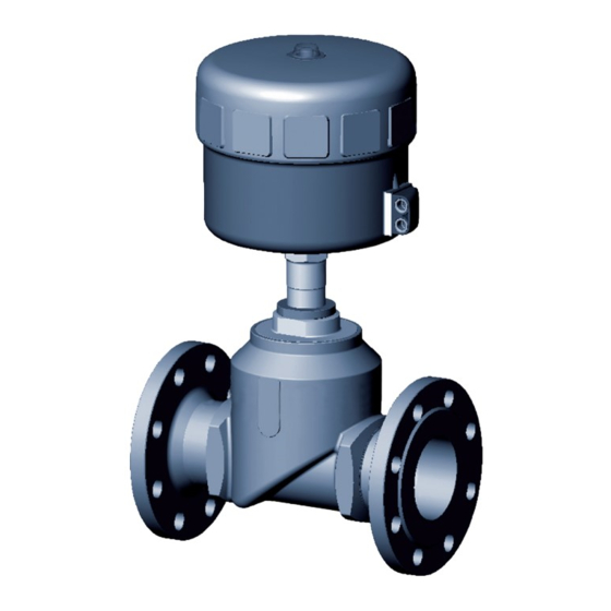
A pressure surge could cause lines and the device to burst. Because of the risk of pressure surge, valves with the flow Wrench flat direction above the seat must not be used for fluid media. for open-end ▶ Observe the type of flow and type of medium for operating Globe wrench the device. body Port connection Fig. 1: Type 2012 globe valve, structure and description English... -
Page 8: Function
Type 2012 Structureandfunction Function 6.2.2 Flow direction below seat Depending on the variant, the valve seat is closed in the direction of Depending on the variant, the valve is closed against the medium or against the medium flow. flow either with spring force (control function A, CFA) or pilot pressure (control function B or I, CFB or CFI). Spring force (CFA) or pneumatic pilot pressure (CFB and CFI) gen- Because the medium pressure is below the swivel plate, it helps erate the closing force on the swivel plate. A spindle connected to open the valve. the actuator piston transmits the force. WARNING! 6.2.1 Control functions (CF) Valve leak if there is too little minimum pilot pressure or high WARNING! medium pressure. For control function I – risk of pilot pressure failure. -
Page 9: Technical Data
Because of the risk of pressure surge, valves with the flow direction above the seat must not be used for fluid media. Flow coefficient ▶ Observe the type of flow and type of medium for operating For derating, Seal material the device. please refer to the operating 2012 A PTFE Kv31 instructions. PS 10bar In order to ensure complete opening, the minimum pilot Control function Tmed -10 - +185 °C pressure must be applied. 2012 A PTFE Kv31 Type see manual for derating... -
Page 10: Conversion Of Actuator Sizes
Type 2012 Technicaldata Conversion of actuator sizes Medium pressure and pilot pressure for control function A, flow direction below seat (standard): Actuator size Desig- Outer diameter Scale drawing [mm] nation A [mm] Maximum medium pressure/minimum pilot pressure Actuator size [mm] 16 (15 *)/4.5 25 (15 *)/3.3 10/4.5 16 (12.5 *)/3.3 7/4.5 16 (10 *)/4.8 * Medium pressure max. 15 bar according to Pressure Tab. -
Page 11: Control Functions
Type 2012 Technicaldata Control functions Control function B and I, flow direction below seat * DN65 DN80 Control function A C losed by spring force in rest position DN100 Control function B O pened by spring force in rest position Control function I A ctuating function via recip- rocal pressurisation Mechanical data Materials Valve body Stainless steel 316L Actuator Pilot pressure [bar] Seal materials P TFE (NBR, FKM, EPDM on Fig. 5: Pressure diagram, control function B and I, flow direction... -
Page 12: Installation
Type 2012 Installation INSTALLATION Before installation Installation position: any, preferably actuator on top. Safety instructions • Ensure that pipelines are in alignment. • Note flow direction. DANGER! • Remove soiling from pipelines. Risk of injury from high pressure in the system. ▶ Before loosening lines and valves, turn off the pressure and Remove actuator from the valve vent the lines. body (welded connection) WARNING! → Clamp valve body into a holding device. Risk of injury due to improper installation. -
Page 13: Installing Valve Body
Type 2012 Installation Installing valve body Install actuator (welded connection) WARNING! Risk of injury due to improper installation. Seal ▶ Installation may only be performed by qualified and trained personnel. ▶ Use an open-end wrench for assembly. Fig. 6: Seal ▶ Observe tightening torques. → Replace seal. WARNING! Dirt trap for devices with approval according to DIN EN 161 According to DIN EN 161 "Automatic shut-off valves for gas burners... -
Page 14: Turning Actuator
Type 2012 Installation Pneumatic connection Tightening torque (Nm) 100 ± 5 120 ± 5 150 ± 5 WARNING! Tab. 2: Tightening torques valve body/nipple Risk of injury due to connecting unsuitable hoses. Turning actuator Hoses that cannot withstand the pressure and temperature range can cause hazardous situations. The position of the ports can be seamlessly aligned by turning the ▶ Only use hoses that are permitted for the specified pressure actuator 360°. and temperature range. ▶ Note the data sheet information from the hose NOTE! manufacturers. Damage to the seat seal or seat contour. -
Page 15: Disassembly
Type 2012 Maintenance,cleaning MAINTENANCE, CLEANING For usage in an aggressive environment, we recommend using a pneumatic hose to drain all free pneumatic ports Safety instructions in a neutral atmosphere. DANGER! Pilot air hose Pilot air hoses of sizes 6 mm, 4 mm or ¼" can be used. Risk of injury from high pressure in the system. ▶ Before loosening lines and valves, turn off the pressure and Disassembly vent the lines. Risk of injury due to electric shock. DANGER! ▶ Before reaching into the system, switch off the power supply and secure against reactivation. Risk of injury from discharge of pressure and escaping medium. -
Page 16: Maintenance Work
Type 2012 Maintenance,cleaning 9.2.1 Cleaning WARNING! Commercially available cleaning agents can be used to clean the For control function I – risk of pilot pressure failure. outside. With control function I, the control unit and reset are pneumatic. NOTE! No defined position is reached during a pressure failure. ▶ To ensure a controlled restart of the device, first apply pilot Avoid causing damage with cleaning agents. pressure and then activate the medium. ▶ Before cleaning, check that the cleaning agents are compati- ble with body materials and seals. Maintenance work Actuator: When used in accordance with these operating instructions, the actuator of the globe valve is maintenance-free. Wearing parts of the globe valve: Parts which are subject to natural wear are: • Valve seat, •... -
Page 17: Replacing The Valve Seat
Type 2012 Maintenance,cleaning Replacing the valve seat Removing actuator from the valve body → Clamp valve body into a holding device. Assembly tool NOTE! Damage to the seat seal or seat contour. ▶ Valve must be open when uninstalling the actuator. Tool attachment → For control function A and I: Pressurise pilot air port with com- (depending on seat pressed air (6 bar): Valve opens. diameter) → Place a suitable open-end wrench on the wrench flat of the Valve seat nipple. -
Page 18: Faults
Type 2012 Faults FAULTS SPARE PARTS CAUTION! Fault Cause Elimination Actuator Pilot air port Connect lower (CFA, CFI) Risk of injury and/or damage due to incorrect parts. does not interchanged or upper (CFB, CFI) pilot Incorrect accessories and unsuitable spare parts may cause switch air port injuries and damage the device and the area around it. Pilot pressure too low Observe pressure spec- ▶ Use only original accessories and original spare parts from ifications on the type Medium pressure too Bürkert. -
Page 19: Overview Of Replacement Part Sets
Type 2012 Transportation,storage,disposal 11.2 Overview of replacement part sets TRANSPORTATION, STORAGE, DISPOSAL NOTE! Transport damage. Seal set for Inadequately protected devices may be damaged during packing gland transport. ▶ Protect the device against moisture and dirt in shock-resis- tant packaging during transport. ▶ Avoid exceeding or dropping below the permitted storage temperature. Incorrect storage may damage the device. ▶ Store the device in a dry and dust-free location. ▶ Storage temperature –20 – +65 °C. Seal set for swivel plate Environmentally compatible disposal... - Page 21 www.burkert.com...
Need help?
Do you have a question about the 2012 and is the answer not in the manual?
Questions and answers