
Related Manuals for Cosen SVT-6070H


Summary of Contents for Cosen SVT-6070H
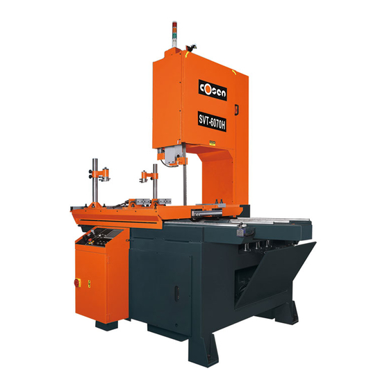
- Page 1 COSEN SAWS SVT-6070H Table Moving Vertical Bandsaw (non-CE Model) Instruction Manual The Pinnacle of Cutting Performance Cosen Mechatronics Co., Ltd.
- Page 3 Instruction Manual: SVT-6070H Table Moving Vertical Bandsaw Ver. 4 2020/7/30 © 2013 by COSEN MECHATRONICS CO., LTD. No part of this publication may be photocopied or otherwise reproduced without the prior written permission of COSEN. Printed in Taiwan...
- Page 5 Safety rules It’s essential to power on your bandsaw machine for at least one hour every two years, if you seldomly use the machine. (This period of power-on must be without proceeding with other operation) Otherwise the machine program may disappear due to not strictly follow this safety rule.
- Page 6 Safety rules Never cut carbon or any other material that may produce and disperse explosive dust. It is possible that sparks from motors and other machine parts will ignite and explode the air-borne dust. Never adjust the wire brush or remove chips while the saw blade is still running.
-
Page 7: Table Of Contents
Table of Contents Safety Information Section 1 – Safety Instructions ……………………………………………………………………………………………………… 1-1 Safeguard Devices ………………………………………………………………………………………………………. 1-3 Emergency Stop …………………………………………………………………………………………………………. 1-4 Illustration: Emergency Stop ……………………………………………………………………………………… Safety Labels ………………………………………………………………………………………………………………. 1-6 Illustration: Safety Labels ………………………………………………………………………………………..… Hearing Protection ……………………………………………………………………………………………………… 1-10 CE Compliance ……………………………………………………………………………………………………………. 1-10 Risk Assessment …………………………………………………………………………………………………………. - Page 8 Table of Contents HMI Error Codes ………………………..……………………………………………………….…………. 4-16 Standard Accessories ………….………………………..……………………………………………….…………… 4-17 Optional Accessories …….…….………………………..…………………………………………….……………… 4-18 Adjusting Wire Brush ………..……………………………………………………………………….………………. 4-20 Adjusting Coolant Flow ………..………..…………………………………………………………………..………. 4-20 Adjusting Blade Speed ………..………..……………………………………………………………………………. 4-21 Unrolling & Installing the Blade …………………………………………………………………….……………. 4-21 Cutting Operation ………..………..……………………………………………..……………………………………. 4-23 Breaking-In the Blade ………..………..…………………………………………………………………..………….
- Page 9 Table of Contents General Troubles & Solutions ………………………..……………………………………………………………. 9-2 Minor Troubles & Solutions ………………………..………………………………………………..……………. 9-3 Motor Troubles & Solutions ………………………..…………………………………………………..…………. 9-3 Blade Troubles & Solutions ………………………..……………………………………………………………….. 9-4 Sawing Problems & Solutions ………………………..…………………………………………………………… 9-5 Re-Adjusting the Roller Table ………………………..……………………………………………………………. 9-12 Parts 10-1 Section 10 –...
-
Page 11: Safety Information
Safety is a combination of a well-designed machine, operator’s knowledge about the machine and alertness at all times. COSEN’s band machine has incorporated many safety measures during the design process and used protective devices to prevent personal injuries and potential risks. Warning labels also serve as a reminder to the operator. - Page 12 This manual has important safety Wear proper apparel during operation information. Read through it carefully and when servicing the machine. Some before operating this machine to personal protective equipment is prevent personal injury or machine required for the safe use of the machine, damage.
-
Page 13: Safeguard Devices
SAFEGUARD DEVICES The safeguard devices incorporated in this machine include the following two main parts: 1. Protection covers & guards 2. Safety-related switches Protection Covers & Guards 1. Idle wheel housing cover 2. Drive wheel housing cover 3. Gear reducer cover 4. -
Page 14: Emergency Stop
Safety Related Switches To protect the operator, the following safety related switches on the machine are actuated when the machine is in operation. Wheel motion detector This is a proximity sensor used to detect the motion of the drive wheel. Once the saw blade is broken as soon as it starts slipping, the sensor will detect and stop the drive wheel and the machine. -
Page 15: Illustration: Emergency Stop
Illustration: Emergency Stop Emergency Stop... -
Page 16: Safety Labels
SAFETY LABELS Safety-related labels mounted on the machine are categorized into the following four categories. Please read through and understand them before operating the machine. Refer to Illustration: Safety Labels. Label Meaning Label Meaning Impact Hazard Read Operator’s Manual WEAR SAFETY SHOES. Do This manual has important safety not approach dropping area information. - Page 17 DANGER Labels A red and white DANGER labels marks s hazards or unsafe practices that will result in severe personal injury or death. Label Meaning Label Meaning Hazardous Voltage DANGER: Running Blade Blade runs through this area. Keep TURN POWER OFF before your hands away from a running servicing.
- Page 18 CAUTION Labels Yellow and black CAUTION labels mark hazards or unsafe practices that can result in considerable personal injury. Label Meaning Keep hands out of the machine while the blade is running. Power to machine must be turned off when changing blades or adjusting wire brush.
- Page 19 SAFETY INSTRUCTION Labels Green and white SAFETY INSTRUCTIONS are important reminders that should be read before operating the machine. Label Meaning 1. Read and understand the instruction manual and warning signs before operating machine. Failure to follow these instructions and warnings can result in serious injury or death.
-
Page 20: Illustration: Safety Labels
Illustration: Safety Labels 1-10... -
Page 21: Hearing Protection
Section 9. CE COMPLIANCE Cosen’s CE model is designed to satisfy regulations of the Council Directive on the approximation of the laws of the Member States relating to machinery (2006/42/EC) - Annex I Essential health and safety requirements relating to the design and construction of machinery. - Page 22 Section 9. CE COMPLIANCE Cosen’s CE model is designed to satisfy regulations of the Council Directive on the approximation of the laws of the Member States relating to machinery (2006/42/EC) - Annex I Essential health and safety requirements relating to the design and construction of machinery.
-
Page 23: General Information
SPECIFICATION MACHINE PARTS IDENTIFICATION FLOOR PLAN This band saw machine is designed by Cosen’s R&D engineers to provide you the following features and advantages: Safety This machine is designed to fully protect the operator from its moving parts during cutting ... - Page 24 SPECIFICATION SVT-6070H Model Table Moving Vertical Bandsaw 600 mm (23.6 in) Height Max. 700 mm (27.6 in) Throat Capacity 1250 mm (49.2 in) Length 15 ~ 100 m/min (50~328 ft/min) Speed 6040 x 54 x 1.6 mm (237.8 x 2.13 x 0.063 in) Size (L x W x T) 38~45kgs / cm2 (Tolerance: +1~+2 kgs / cm²...
- Page 25 MACHINE PARTS IDENTIFICATION...
-
Page 26: Floor Plan
FLOOR PLAN Machine top view Machine side view... -
Page 27: Moving & Installation
Section 3 MOVING & INSTALLATION LOCATION & ENVIRONMENT UNPACKING & INSPECTING LIFTING REMOVING SHIPPING BRACKET CLEANING INSTALLING RELOCATING LOCATION & ENVIRONMENT For your safety, please read all information regarding installation before proceeding. Install your machine in a place satisfying all of the following conditions: Space: Leave enough free space around the machine for loading work and unloading cut-off pieces ... -
Page 28: Unpacking & Inspecting
UNPACKING & INSPECTING Unpack your machine carefully to avoid damage to machine parts or surfaces. Upon arrival of your new band saw, please confirm that your machine is the correct model and it comes in the same specification you ordered by checking the model plate on the machine base. It is also imperative that a thorough inspection be undertaken to check for any damage that ... -
Page 29: Lifting
LIFTING When moving the machine, we strongly suggest you choose any one of the methods described below to move your machine. 1. Use a crane Move the machine to its location by using a crane and a wire rope sling that can fully withstand the weight of the machine (refer to machine specification under Section 1 Description). -
Page 30: Illustration: Lifting Points
Illustration: Lifting Points Minimum weight capacity for each band/chain/wire rope: 5 ton Total number of band/chain/wire rope required: 3... - Page 31 2. Use a forklift Most users choose this method to move their machine because it is easy to set up. Make sure that the lifting rod can fully withstand the weight of the machine. (Refer to Section 2 – General Information for Specifications) Machine lifting is likely to damage the machine ...
-
Page 32: Removing Shipping Bracket
Do not remove the rust-preventive grease with a metal scraper and do not wipe the painted surfaces with solvent as doing so would damage surface paint. INSTALLING Cosen’s bandsaw machine is relatively easy to install. Follow these six easy steps to install your machine. Connect Leveling &... -
Page 33: Supplying Coolant
Have a qualified electrician make the electrical connections. If the power supply voltage is different from the transformer and motor connection voltage shown on the label attached to the electrical compartment of the machine, contact COSEN or your agent immediately. - Page 34 Turn off the shop circuit breaker. Make sure the machine circuit breaker switch on the electrical compartment door is turned to OFF. Remove the screw securing the electrical compartment and then open the door. Pull the power supply cable and grounding conductor through the power supply inlet into the electrical compartment.
-
Page 35: Installing Roller Table (Optional)
Anchoring the machine Normally there is no need to anchor the machine. If the machine is likely to vibrate, fix the machine to the floor with anchor bolts. Shock absorption steel plates are provided and can be placed under each leveling bolt to prevent their sinking into the concrete floor. -
Page 37: Operating Instructions
Section 4 OPERATING INSTRUCTION SAFETY PRECAUTIONS BEFORE OPERATING CONTROL PANEL STANDARD ACCESSORIES OPTIONAL ACCESSORIES ADJUSTING WIRE BRUSH ADJUSTING COOLANT FLOW ADJUSTING BLADE SPEED UNROLLING & INSTALLING THE BLADE CUTTING OPERATION BREAKING-IN THE BLADE TERMINATING A CUTTING OPERATION... -
Page 38: Safety Precautions
SAFETY PRECAUTIONS For your safety, please read and understand the instruction manual before you operate the machine. The operator should always follow these safety guidelines: The machine should only be used for its designated purpose. Do not wear gloves, neckties, jewelry or loose clothing/hair while operating the ... -
Page 39: Before Operating
BEFORE OPERATING Choosing an appropriate saw blade and using the right cutting method is essential to your cutting efficiency and safety. Select a suitable saw blade and cutting method based on your work material and job requirements e.g. cutting accuracy, cutting speed, economic concern, and safety control. Wet cutting If you choose dry cutting or low-speed cutting, the chips may accumulate in machine parts and may cause operation failure or insulation malfunction. -
Page 40: Control Panel
CONTROL PANEL The control panel is located on the top of the electrical box. It includes the following function: power system, hydraulic system, cooling system, the human-machine–interface (HMI) and the projecting light system. The operator must fully understand the function of each switch and button before operating the machine. -
Page 41: Control Buttons
Control Buttons 1. Emergency stop button Press this button to stop the machine in an emergency. When the button is pressed, it brings the machine to a full stop. The button locks when pressed. In order to unlock it, please turn the button clockwise. -
Page 42: Hmi Touch Screen & Functions
Stop cutting for single feeding mode and repeat feeding mode: During cutting, press this button to stop the running blade. The workbed will also move slightly away from the blade in order to protect the blade. 8. HMI touch screen Please refer to later section for detailed introduction. - Page 43 RS422 MMI port Environment No condensation and rust Startup Screen After the power is turned on, Cosen’s logo will appear as the startup screen, followed by the main operation menu.. Main control menu The main control menu includes some operating button that were used on the control panel of the earlier machines.
- Page 44 Refer to the table below for descriptions of each function. Item Function Description Hydraulic start When the power is turned on, press this button to start the hydraulic motor. A solid yellow icon indicates the hydraulic system has been turned on. Hydraulic stop Press this button to turn off the hydraulic motor immediately.
- Page 45 Item Function Description blade, press saw blade stop button. Before starting the saw blade, please choose the feeding mode first. Once the saw blade is running, the saw blade needs to be stopped to be able to switch the feeding mode. Single feeding mode Press this button to switch to the single feeding mode.
- Page 46 Item Function Description The laser light automatically turns off in 90 seconds to prolong light bulb lifetime. Guide arm up Press this button to bring the guide arm up away from the workbed. Use this function when you need to adjust the distance between the guide arm and the workbed/material.
- Page 47 Item Function Description Right limit switch When the movable workbed feeds to the very ON/OFF right end and touches the right side limit switch, the movable workbed will stop and the green light will come on. Blade speed Current blade speed display Current table position The relative position according to the current return-to-zero table position.
- Page 48 Item Function Description Blade speed control Press “+” to speed up the blade. Press “-“ to speed down the blade Cutting status display & setup When cutting is in operation, press to enter cutting status display and setup page. Page 1 – cutting status display and set up 1 This page shows or sets the following information (from top to bottom): Set Height –...
- Page 49 Page 2 – cutting program setup In this page you can set the following value (from top to bottom) for the repeat feeding mode: Hydraulic start – Same as above descriptions in main control menu Hydraulic stop – Same as above descriptions in ...
- Page 50 Material cutting reference This reference chart lists out the required blade speed and cutting rate for 7 different groups of material. Press Home to return to the main control menu. Press PGUP to go back to the previous setup ...
- Page 51 Error Error Description Solution Code M300 Front vises not clamping Check if the queen valve works M301 Rear vises not clamping Check if the queen valve works M303 Lower limit switch error Check if the lower limit switch works M304 Hydraulic motor not starting Check if the hydraulic motor works M306...
-
Page 52: Standard Accessories
STANDARD ACCESSORIES Chip Conveyor The chip conveyor is designed to bring chips out during cutting. When the hydraulic system is on, adjust the pressure control valve to adjust the conveying speed. Pressure control valve & meter Conveyor modes: Conveyor mode 1. -
Page 53: Optional Accessories
Gear Reducer The specially designed gear reducer can work toward your preset blade speed and torque. Please refer to Section 8 for information on maintenance. Gear reducer Coolant Pump After the hydraulic system is turned on, the coolant pump can be operated independently via HMI touch panel. Besides cooling off the running blade, it can also be used to wash the machine. - Page 54 Throat measuring stopper & auxiliary side stoppers Step 1: Adjust throat measuring stopper The throat measuring stopper becomes very useful when determining where to locate the material at. Auxiliary side Position the throat measuring stopper at your desired cutoff stopper throat size on the measuring tape.
-
Page 55: Adjusting Wire Brush
ADJUSTING WIRE BRUSH Follow these steps to adjust wire brush to appropriate position: Step 1 – Loosen the wire brush assembly lock nuts. Step 2 - Remove the old worn wire brush and replace with new one. Step 3 – Tighten the wire brush assembly lock nuts. Step 4 –... -
Page 56: Adjusting Blade Speed
If the chips are sharp and curved, increase the coolant flow amount. If the chips are granulated, decrease the coolant flow amount. ADJUSTING BLADE SPEED Step 1 – Set the flow control to “0” position. Step 2 – Press the saw blade start button to start the blade. Step 3 –... - Page 57 Installing a new blade A – Workbed crosslink B – Workbed tri-lifters Step 1 - Select the most suitable saw blade for your workpiece considering the size, shape and material. Step 2 - Turn on the machine power by switching to ON and turn on the hydraulic system. Step 3 - Press the workbed to the left button and send the workbed all the way to the left end (if facing the control panel).
-
Page 58: Cutting Operation
CUTTING OPERATION Step 1 – Check before you cut Power: Check the voltage and frequency of your power source. Coolant: Check if you have sufficient coolant in the tank. Hydraulic: Check if you have sufficient (at least two-thirds or higher) hydraulic oil. ... -
Page 59: Breaking-In The Blade
BREAKING-IN THE BLADE When a new saw blade is used, be sure to first break in the blade before using it for actual, extended operation. Failure to break in the blade will result in less than optimum efficiency. To perform this break-in operation, the following instructions should be followed: Step 1 - Reduce the blade speed to one-half of its normal setting. -
Page 61: Electrical System
Section 5 ELECTRICAL SYSTEM ELECTRICAL CIRCUIT DIAGRAMS The following are electrical circuit diagrams of the system: Fig 5‐1 Control panel layout Fig 5‐2 Circuit board layout Fig 5‐3 Power supply layout Fig 5‐4 PLC I/O layout 5‐1... - Page 62 Fig.5‐1 Control panel layout 5‐2 ...
- Page 63 Fig.5‐2 Circuit board layout 5‐3...
- Page 64 Fig.5‐3 Power supply layout 5‐4 ...
- Page 65 Fig.5‐4 PLC I/O layout 5‐5...
-
Page 67: Hydraulic System
Section 6 HYDRAULIC SYSTEM HYDRAULIC DIAGRAM 6‐1... - Page 68 Fig. 6‐1 Hydraulic layout 6‐2...
-
Page 69: Bandsaw Cutting: A Practical Guide
Section 7 BANDSAW CUTTING: A PRACTICAL GUIDE INTRODUCTION SAW BLADE SELECTION VISE LOADING BLADE BREAK-IN... - Page 70 INTRODUCTION TPI: The number of teeth per inch as measured from gullet to gullet. 2. Tooth Rake Angle: The angle of the tooth face measured with respect to a line perpendicular to the cutting direction of the saw. 3.Tooth Pitch: Tooth pitch refers to the number of teeth per inch (tpi). 1 inch equates to 25.4 mm. A distinction is made between constant tooth pitches with a uniform tooth distance, 2 tpi for example, and variable tooth pitches with different tooth distances within one toothing interval.
- Page 71 4. Tooth pitch The main factor here is the contact length of the blade in the workpiece. If it is 4P, 25.4 ÷ 4 P = 6.35 mm, that is, one tooth is 6.35 mm. If it is 3P, 25.4 ÷ 3 P = 8.46 mm If the number is small, it means that the tooth is large. What is written as 3/4 is that it is a variable pitch of large (3) / small (4).
- Page 72 The following diagrams suggest some costeffective ways of loading and fixturing. Be sure, regardless of the arrangement selected, that the work can be firmly secured to avoid damage to the machine or injury to the operator. BLADE BREAK-IN Completing a proper break-in on a new band saw blade will dramatically increase its life. 1.
-
Page 73: Maintenance & Service
Section 8 MAINTENANCE & SERVICE INTRODUCTION BASIC MAINTENANCE MAINTENANCE SCHEDULE BEFORE BEGINNING A DAY’S WORK AFTER ENDING A DAY’S WORK Every 2 weeks First 600hrs for new machine,then every 1200hrs for routine change EVERY SIX MONTHS STORAGE CONDITIONS TERMINATING THE USE OF MACHINE OIL RECOMMENDATION FOR MAINTENANCE INTRODUCTION For the best performance and longer life of the band saw machine, a maintenance schedule is... - Page 74 MAINTENANCE SCHEDULE We suggest you do the maintenance on schedule. Before beginning a day’s work 1. Please check the hydraulic oil level. If oil level volume is below 1/2, please add oil as necessary.(Filling up to 2/3 level is better for system operation.) 2.
- Page 75 Grease Injection Hole: Grease Injection Nozzles at the middle of drive wheel Grease Injection Nozzle and idle wheel; (You need to rotate the wheel until you ssee the Grease injection nozzle.) : The position of injection indicating. Please inject the grease into the Nozzle. 1.
- Page 76 (if applicable) Manual Lubrication Injection Device: Lubrication volume indicator. Recommend keeping the volume over 50% inside the vessel. Please take down this vessel cap to replenish the lubrication. For the prevention of working environment pollution, DO NOT replenish too much volume of lubrication while supplying the lubrication into the vessel.
- Page 77 Gear Oil & Grease Injection Hole : 1. A grease injection hole and a gear oil injection Grease Injection Nozzle hole on the top of gear reducer. : The position of injection indicating. Gear Oil Injection Hole Recommend keeping the volume over 50% inside 。...
- Page 78 TERMINATING THE USE OF THE MACHINE Waste disposal: When your machine can not work anymore, you should drain the oil from machine body. Please store the oil in safe place with bottom tray. Ask a environment specialist to handle the oil. It can avoid soil pollution.
-
Page 79: Troubleshooting
Section 9 TROUBLESHOOTING INTRODUCTION PRECAUTIONS GENERAL TROUBLES & SOLUTIONS MINOR TROUBLES & SOLUTIONS MOTOR TROUBLES & SOLUTIONS BLADE TROUBLES & SOLUTIONS SAWING PROBLEMS & SOLUTIONS RE-ADJUSTING THE ROLLER TABLE INTRODUCTION All the machines manufactured by us pass a 72 hours continuously running test before shipping out and we are responsible for the after sales service problems during the warranty period if the machines are used normally. - Page 80 PRECAUTIONS When an abnormality occurs in the machine during operation, you can do it yourself safely. If you have to stop machine motion immediately for parts exchanging, you should do so according to the following procedures: Press HYDRAULIC MOTOR OFF button or EMERGENCY STOP button. ...
-
Page 81: Motor Troubles & Solutions
MINOR TROUBLES & SOLUTIONS TROUBLE PROBABLE CAUSE SUGGESTED REMEDY Saw blade motor does not run Overload relay activated Reset even though blade drive button Saw blade is not at forward Press SAW FRAME is pressed. limit position. FORWARD button MOTOR TROUBLES & SOLUTIONS TROUBLE PROBABLE CAUSE SUGGESTED REMEDY... -
Page 82: Blade Troubles & Solutions
BLADE TROUBLES AND SOLUTIONS DISCONNECT POWER CORD TO MOTOR BEFOER ATTEMPTING ANY REPAIR OR INSPECTION. TROUBLE PROBABLE CAUSE SUGGESTED REMEDY Too few teeth per inch Use finer tooth blade Loading of gullets Use coarse tooth blade or cutting lubricant. Teeth strippage Excessive feed Decrease feed... -
Page 83: Sawing Problems & Solutions
SAWING PROBLEMS AND SOLUTIONS Other than this manual, the manufacturer also provides some related technical documents listed as follows: Sawing Problems and Solutions Vibration during cutting Failure to cut Short life of saw blade Curved cutting Broken blade ... - Page 84 SOLUTIONS TO SAWING PROBLEMS Table Of Contents #1. Heavy Even Wear On Tips and Corners Of Teeth #11. Uneven Wear Or Scoring On The Sides Of Band #2. Wear On Both Sides Of Teeth #12. Heavy Wear And/Or Swagging On Back Edge #3.
- Page 85 #2. Wear On Both Sides Of Teeth Probable Cause : A. Broken, worn or missing back-up guides allowing teeth to contact side guides. B. Improper side guides for band width. C. Backing the band out of an incomplete cut. #3. Wear On One Side Of Teeth Probable Cause : A.
- Page 86 #5. Body Breakage Or Cracks From Back Edge Probable Cause : A. Excessive back-up guide "preload" will cause back edge to work harden which results in cracking. B. Excessive feed rate. C. Improper band tracking – back edge rubbing heavy on wheel flange.
- Page 87 #8. Gullets Loading Up With Material Probable Cause : A. Too fine of a tooth pitch – insufficient gullet capacity. B. Excessive feeding rate producing too large of a chip. C. Worn, missing or improperly positioned chip brush. D. Insufficient sawing fluid due to inadequate supply, improper ratio and/or improper application.
- Page 88 #12. Heavy Wear And/Or Swagging On Back Edge Probable Cause : A. Excessive feed rate. B. Excessive back-up guide "preload". C. Improper band tracking – back edge rubbing heavy on wheel flange. D. Worn or defective back-up guides. #13. Butt Weld Breakage Probable Cause : A.
- Page 89 #16. Body Breakage Or Cracks From Gullets Probable Cause : A. Excessive back-up guide "preload". B. Improper band tension. C. Guide arms spread to maximum capacity. D. Improper beam bar alignment. E. Side guide adjustment is too tight. F. Excessively worn teeth. #17.
-
Page 90: Re-Adjusting The Roller Table
#20. Broken Band Shows A Twist In Band Length Probable Cause : A. Excessive band tension B. Any of the band conditions which cause the band to be long (#18) or short (#19) on tooth edge. C. Cutting a tight radius. RE-ADJUSTING THE ROLLER TABLE If the feeding table suffers the huge stroke and the alignment is effected, follow the below procedure to adjust. -
Page 91: Parts
Rubber washer Duster seal Gear reducer Oil seal O-ring Snap ring Drive wheel Idle wheel 註記: 下訂單前, 請務必與高聖客服代表確認產品品號是否適用於您需求的產品. Remark: Please make sure the parts number that is applicable for the products with Cosen's customer service before purchasing items. 10-1... - Page 92 SVT-6070H PART NO. PART NAME 1 Base and bed Base and bed assembly assembly 3 Saw bow assembly Saw bow assembly 5 V6070T-41000 Mechanic top clamp assembly 7 V6070T-47000 manual feeding device 9 V6070T-46000 stopper device 11 V6070T-40000 scraper type chip...
- Page 93 Base and bed assembly PART NO. PART NAME 1 V6070T-1001 Base 3 V6070T-1002 Oil tank 5 V6070T-1003 Hydraulics tank cover 7 V6070T-1004 Asbestos 9 V6070T-1051 Left side cover 11 V6070T-1053 Right side cover 13 V6070T-1055 Front cover 15 V6070T-1059 Rear cover 17 V6070T-1301 Electircal box 19 V6070T-1321A...
- Page 94 Saw bow assembly PART NO. PART NAME 1 V6070T-3001 top saw bow 3 V6070T-3002 lower saw bow 5 NGG-32000E Planetary gearbox 7 V6070T-3041 drive wheel 9 V6070T-30300 Idle wheel assembly 11 V6070T-3311 Tension cover 13 SGJ-21010 Tensioner sliding assembly 15 SGJ-21030 Tensioner cylinder assembly 17 V6068T-31000 Movable guide arm assembly 1...
- Page 95 V6070T-30300 PART NO. PART NAME 1 V6070T-3031 Idle wheel 3 SVD-3016B Idle wheel shaft 5 SVD-3018A Bearing cover 7 SVD-3019 Washer 9 V4060-3039 Bearing shield 11 PP-14628 Bearing 30218 13 PP-14918 Ring AW11 15 PP-14968 Ring AW18 17 SGJ-2011 Idle wheel shaft fixed plate 10-4...
- Page 96 PART NO. PART NAME V6068T-31000 1 SVD-3002A Movable guide arm 3 SVD-3004 Sliding seat cover 5 SVD-3006 Saw arm locked tube 7 SVD-3007 Saw arm slide side plate 9 SVD-3008 Saw arm locked piston 11 SVD-3011 Connecting shaft 13 SVD-3012 Adjusting plate 15 PP-43448A Cylinder...
- Page 97 SVD-30250 PART NO. PART NAME 1 SVD-3025 Guilde wheel seat 3 SVD-3040 Movable carbide insert 5 SVD-3041 Fixed carbide insert 7 PP-59070 O Ring 9 AHA-0704A Clamping seat 11 AGB-70716 Spring 13 AGB-70715 Cylinder 15 AGB-70416 Locked pistion 17 AGB-70410A 10-6...
- Page 98 PART NO. PART NAME SVD-30290 1 SVD-3040 Movable carbide insert 3 SVD-3041 Fixed carbide insert 5 PP-59070 O Ring 7 AHA-0704A Clamping seat 9 AGB-70716 Spring 11 AGB-70715 Cylinder 13 AGB-70416 Locked pistion 15 AGB-70410A 17 SVD-3029 Guilde wheel seat 10-7...
- Page 99 SVD-32200 PART NO. PART NAME 1 SVD-3225 Wire brush fixed seat 3 SVD-3224 Adjusting block 5 SVD-3223 Adjusting sea 7 SVD-3222 Wire brush shaft 9 SVD-3221 Sliding shaft 11 SVD-3220 Motor seat 13 SVD-3046 Hydraulic and coolant extended connector 15 PP-58002 Wire brush 17 PP-31640-4 Hydraulic motor...
- Page 100 PART NO. PART NAME V6070T-41000 1 V6070T-4101 Clamping seat 3 V6070T-4103 Turning seat 5 V6070T-4105 Block seat 7 V6070T-4109 Clamping block 9 PP-91322 T type bolt 11 PP-91321 T type nut 13 PP-53010 Screw 15 AGB-70304A 17 AHB-0613 Motor pulley lock washer 10-9...
- Page 101 V6070T-47000 PART NO. PART NAME 1 V6070T-4701 Manual feeding seat 3 V6070T-4703 Manual shaft seat 5 V6070T-4705 Manual screw 7 V6070T-4707 Manaul brake ring 9 V6070T-4709 Manual push plate 11 V6070T-4711 Manual pushing guide 13 PP-91321 T slot nut 15 PP-91322 T typle nut 17 PP-14812 Plane bearing...
- Page 102 V6070T-46000 PART NO. PART NAME 1 V6070T-4601 Gapping block 3 PP-91321 T slot nut 5 PP-91322 T typle nut 10-11...
- Page 103 V6070T-40000 PART NO. PART NAME 1 V6070T-4001 Chip conveyor tank 3 V6070T-4017 Supporting angle iron 5 V6070T-4019 Supporting angle iron 7 V6070T-4035 Cover 9 PP-12016 Bearig(UCF-205) 11 PP-14137 Bearing 6006VV 13 PP-31640-1 Hydraulic motor 15 PP-31654B Gearbox 17 PP-43127B Pressure regulator 19 PP-43311 Pressure gauge 21 PP-43842...
- Page 106 COSEN SAWS Vertical Plate Saws Horizontal Billet Saws NC/CNC Band Saws Structural Miter-Cutting Saws Automatic Band Saws Industry 4.0 Cosen Predictive Computing Visit our website at www.cosen.com COSEN MECHATRONICS CO., LTD.
Need help?
Do you have a question about the SVT-6070H and is the answer not in the manual?
Questions and answers