
Related Manuals for Cosen SH-1000F


Summary of Contents for Cosen SH-1000F
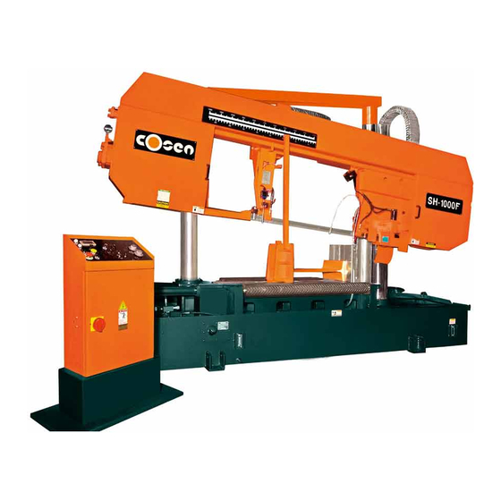
- Page 1 COSEN╱SAWS SH-1000F Semi-Automatic Double Column Canted Frame Straight Cutting Bandsaw (Non-CE Model) Instruction Manual The Pinnacle of Cutting Performance Cosen Mechatronics Co., Ltd.
- Page 3 FROM THE MANUFACTURER Thank you for your purchase of COSEN’s bandsaw machine and your trust in the COSEN brand. We are excited to have you as our valued customer and look forward as much as you do to the accelerated productivity, long-lasting endurance and superb cost-effectiveness this machine is about to bring to you.
- Page 5 Safety rules Make sure your work area is cleared of uninvited people and obstacles every time before you start operating the machine. Never step or stand on the roller table. Your foot may slip or trip on the rollers and you will fall.
- Page 6 Safety rules Never adjust the wire brush or remove chips while the saw blade is still running. It is extremely dangerous if hands or clothing are caught by the running blade. Stop the saw blade before you clean the machine. It is dangerous if hands or clothing are caught by the running blade.
-
Page 7: Table Of Contents
Table of Contents Safety Information Section 1 – Safety Instructions ……………………………………………………………………………………………………… 1-1 Safeguard Devices ………………………………………………………………………………………………………. 1-3 Emergency Stop …………………………………………………………………………………………………………. 1-4 Illustration: Emergency Stop ……………………………………………………………………………………… Safety Labels ………………………………………………………………………………………………………………. 1-6 Illustration: Safety Labels ………………………………………………………………………………………..… Hearing Protection ……………………………………………………………………………………………………… 1-10 CE Compliance ……………………………………………………………………………………………………………. 1-10 Risk Assessment …………………………………………………………………………………………………………. - Page 8 Table of Contents Control Buttons ……………………………………………………………………………………….…….. 4-5 Blade Descend Pressure & Speed ………..…………………………………………………….…… 4-8 Standard Accessories ………….………………………..……………………………………………….…………… 4-9 Optional Accessories …….…….………………………..…………………………………………….……………… 4-11 Unrolling & Installing the Blade …………………………………………………………………….……………. 4-12 Adjusting Wire Brush ………..……………………………………………………………………….………………. 4-14 Adjusting Coolant Flow ………..………..…………………………………………………………………..…….… 4-14 Adjusting Saw Arm ………..……………………………………………………………………….………………….. 4-15 Adjusting Blade Speed ………..………..………………………………………………………………………….…...
- Page 9 Table of Contents Troubleshooting Section 9 – Introduction ……………………….…….…………………..……………………………………………………………. 9-1 Precautions ………………….…………………..……………………………………………………………………..9-1 General Troubles & Solutions ………………………..……………………………………………………………. 9-2 Minor Troubles & Solutions ………………………..………………………………………………..……………. 9-3 Motor Troubles & Solutions ………………………..…………………………………………………..…………. 9-3 Blade Troubles & Solutions ………………………..……………………………………………………………….. 9-4 Sawing Problems & Solutions ………………………..…………………………………………………………… 9-5 Re-Adjusting the Roller Table ………………………..…………………………………………………………….
-
Page 11: Safety Information
Section 1 SAFETY INFORMATION SAFETY INSTRUCTIONS SAFEGUARD DEVICES EMERGENCY STOP SAFETY LABELS HEARING PROTECTION CE COMPLIANCE RISK ASSESSMENT Safety is a combination of a well‐designed machine, operator’s knowledge about the machine and alertness at all times. COSEN’s band machine has incorporated many safety measures during the design process and used protective devices to prevent personal injuries and potential risks. Warning labels also serve as a reminder to the operator. Throughout this manual, you will also see various safety‐related symbols indicating important information that you should take note of prior to use of the machine or part of its functions. These important safety instructions do not cover all possible situations that might occur. It is your responsibility to take caution and follow procedures stated in this manual when installing, maintaining and operating your machine. Cosen will not be liable for damages resulting from improper use. SAFETY INSTRUCTIONS What the icons and signs in this user manual mean: This icon marks DANGER; hazards or unsafe practices that may result in severe personal injury or death. This icon marks WARNING; hazards or unsafe practices that may result in personal injury or damage to the machine. This icon marks CAUTION; information that should be read before use to prevent damage to the machine. Supplementary information to the procedures described in this manual. Call your local agent or our service center for help. ... - Page 12 This manual has important safety All users must read it before performing any information. Read through it carefully activity on the machine, such as replacing before operating this machine to prevent the saw band or doing regular maintenance. personal injury or machine damage. Learn the operation, limitation and the specific Some personal protective equipment is potential hazards peculiar to this band required for the safe use of the machine, e.g. protection goggles. saw. Do not operate this machine unless it is Keep blade protection cover and wheel completely assembled. covers in place and in working order. Make sure the power switch is off before Use recommended accessories. Improper plugging in power cord. accessories may be hazardous. Disconnect the power cord before making Keep your work area well illuminated at adjustment, maintenance or blade minimum 500 lumen. changes. Keep your work area clean. Cluttered and Keep all guards and shields in place before slippery floors invite accidents. installing or starting up the machine. Remove adjusting keys, wrenches or any Wear proper apparel during operation loose parts or items from the machine and when servicing the machine. ...
-
Page 13: Safeguard Devices
SAFEGUARD DEVICES The safeguard devices incorporated in this machine include the following two main parts: 1. Protection covers & guards 2. Safety‐related switches Protection Covers & Guards 1. Idle wheel housing cover 2. Drive wheel housing cover 3. Gear reducer cover 4. Wire brush belt cover 5. Blade guard cover (left & right) The protection devices should always be mounted on the machine whenever the machine is running. Do not remove any of these safeguard devices under any circumstances except when servicing the machine. Even skilled service technicians should still take cautions when performing repairs or service on the machine with any of these protectors removed. It is the responsibility of the user to make sure all these elements are not lost and damaged. Take note of the following main moving parts on the machine prior to and during machine operation: Saw bow assembly Drive and idle wheels Blade guide arm Saw blade guide rollers Quick approach device Wire brush Chip conveyor (optional) Workpiece clamping vises ... -
Page 14: Emergency Stop
Safety Related Switches To protect the operator, the following safety related switches on the machine are actuated when the machine is in operation. Wheel motion detector This is a proximity sensor used to detect the motion of the drive wheel. Once the saw blade is broken or as soon as it starts slipping, the sensor will detect and stop the drive wheel and the machine. Power switch Located on the cover of electrical cabinet, the power switch controls the main power of the machine. Up to your company’s internal rules, this power switch can be locked with a padlock or a luggage lock to protect the operator and the machine. Emergency stop button Located on the control panel, the button when pressed will stop the machine completely. Vise clamp switch This switch assures firm clamping of the workpiece. If the workpiece is not clamped properly, the saw blade is not allowed to run. Wheel cover interlock switches Located on the two wheel housings, these switches (CE model only) are used to assure that the machine will stop whenever the wheel covers are open. This device is to protect users from being cut by the running saw blades. Among all these safety switches, some of them are used to protect the users and some of them are used to prevent damage to saw blades, the workpiece and the machine itself, etc. We have taken every precaution to prevent injury or damage and to provide safe and economical operation of the machine. EMERGENCY STOP Designed to be easily accessible, the emergency stop button is located on the left bottom corner on the control panel and is made in red color and rubber material. For CE models, supplementary emergency stop button may be available at other area(s) of the machine depending on machine type. ... -
Page 15: Illustration: Emergency Stop
Illustration: Emergency Stop Emergency Stop Button 1‐5... -
Page 16: Safety Labels
SAFETY LABELS Safety‐related labels mounted on the machine are categorized into the following four categories. Please read through and understand them before operating the machine. Refer to Illustration: Safety Labels. DANGER Labels A red and white DANGER labels marks s hazards or unsafe practices that will result in severe personal injury or death. Label Meaning Label Meaning Hazardous Voltage DANGER: Running Blade Blade runs through this area. Keep TURN POWER OFF before your hands away from a running servicing. Failure to blade to avoid severe injury. The following the warning can arrow indicates direction of the result in severe injury. blade. WARNING Labels An orange and black WARNING label marks hazards or unsafe practices that can result in severe personal injury or damage to the machine. Label Meaning Label Meaning Cutting Hazard Cutting Hazard KEEP COVER CLOSED while KEEP HAND OFF while the blade is ... - Page 17 CAUTION Labels Yellow and black CAUTION labels mark hazards or unsafe practices that can result in considerable personal injury. Label Meaning Keep hands out of the machine while the blade is running. Power to machine must be turned off when changing blades or adjusting wire brush. NOTICE Labels Blue and white NOTICE labels mean unsafe practices that could result in damage to products or property. Label Meaning Replace the hydraulic oil every six months or every 1,200 hours of operation. Oil specification: Shell TELLUS 27 or Mobil DTE OIL LIGHT / HYDRAULIC 28 To extend blade life, always adjust the location of wire brush so that it is properly touching the blade. Also replace a worn wire brush with a new one. 1‐7...
- Page 18 SAFETY INSTRUCTION Labels Green and white SAFETY INSTRUCTIONS are important reminders that should be read before operating the machine. Label Meaning 1. Read and understand the instruction manual and warning signs before operating machine. Failure to follow these instructions and warnings can result in serious injury or death. 2. Do not wear gloves, neckties, jewelry or loose clothing while operating the machine. 3. Always wear eye protection goggles. 4. Check blade tension and adjust blade guide before starting to cut. 5. Always clamp stock firmly in place before cutting. 6. Do not remove jammed or cut‐off pieces until blade has stopped. 7. Keep fingers out of path of blade. 8. Blade guards should be in place and used at all times. 9. Disconnect machine from power source before marking repairs or adjustments. 10. Do not operate while under the influence of drugs, alcohol or medication. 1‐8 ...
-
Page 19: Illustration: Safety Labels
Illustration: Safety Labels 1‐9... -
Page 20: Hearing Protection
Drive wheel Parts not assembled tightly causing mechanical vibration When your machine is running, noise will come out. This is a machine‐electric interface problem that may make people feel uncomfortable. Our products pass noise testing less than 78 dBA. If your machine produces an undesirable noise while it is running, you should: Make sure all maintenance tasks have been performed following the prescribed maintenance schedule (Refer to Section 8). If maintenance does not seem to solve the problem, follow the troubleshooting procedures under Section 9. CE COMPLIANCE Cosen’s CE model is designed to satisfy regulations of the Council Directive on the approximation of the laws of the Member States relating to machinery (2006/42/EC) ‐ Annex I Essential health and safety requirements relating to the design and construction of machinery. RISK ASSESSMENT Risk assessment generally takes account of intended use and foreseeable misuse, including process control and maintenance requirements. We made every effort to avoid any personal injury or equipment damage during the machine design stage. However, the operator (or other people) still needs to take precautions when handling any part of the machine that is unfamiliar and anywhere on the machine that has potential hazards (e.g. the electrical control box). 1‐10 ... -
Page 21: General Information
INFORMATION SPECIFICATION MACHINE PARTS IDENTIFICATION FLOOR PLAN This band saw machine is designed by Cosen’s R&D engineers to provide you the following features and advantages: Safety This machine is designed to fully protect the operator from its moving parts during cutting operation. - Page 22 SPECIFICATION SH-1000F Model Semi-Automatic Double Column Canted Frame Straight Cutting Bandsaw 7.5° Blade Cant 660 mm (26 in) Round 520 mm (20.5 in) Square Capacity 520 x 1,020 mm (20.5 x 40.1 in) Rectangular (H x W) W: 218 ~ 1,011 mm (8.5 ~ 39.8 in) Bundle Cutting H: 170 ~ 713 mm (6.6 ~ 28.0 in)
- Page 23 MACHINE PARTS IDENTIFICATION Double Column Cross Link Idle Wheel Blade Guide Arm Control Panel Drive Wheel with Dual Control Valves Wire Brush Assembly Front Vise Cylinder Electrical Compartment Front Vise Machine front view...
-
Page 24: Floor Plan
FLOOR PLAN Machine top view Machine front view... -
Page 25: Moving & Installation
Section 3 MOVING & INSTALLATION LOCATION & ENVIRONMENT UNPACKING & INSPECTING LIFTING REMOVING SHIPPING BRACKET CLEANING INSTALLING RELOCATING LOCATION & ENVIRONMENT For your safety, please read all information regarding installation before proceeding. Install your machine in a place satisfying all of the following conditions: Space: Leave enough free space around the machine for loading work and unloading cut‐off pieces as well as for maintenance and inspection. Refer to Section 2 General Information for machine dimensions and floor space. Environment: Well lighted (500 lumen at minimum). Floor kept dry at all times in order to prevent operators from slipping. Away from direct exposure to the sunlight Room temperature between 5˚C to 40˚C. Humidity level kept at 30 ~95%“(without condensation) to avoid dew on electric installation and machine. Away from vibration of other machines Away from powders or dusts emitted from other machines ... -
Page 26: Unpacking & Inspecting
UNPACKING & INSPECTING Unpack your machine carefully to avoid damage to machine parts or surfaces. Upon arrival of your new band saw, please confirm that your machine is the correct model and it comes in the same specification you ordered by checking the model plate on the machine base. It is also imperative that a thorough inspection be undertaken to check for any damage that could have occurred during shipping. Pay special attention to machine surface, equipments furnished and the electrical and hydraulic systems for damaged cords, hoses and fluid leaks. In the event of damage caused during shipping, please contact your dealer and consult about filing a damage claim with the carrier. Your machine comes in with a set of tools for you to maintain the machine. The accessories furnished are as follows: 1. Tool box 1 pc 2. Grease gun 1 pc 3. Screwdriver (+, ‐) 2 pcs 4. Open‐ended spanner ... -
Page 27: Lifting
LIFTING When moving the machine, we strongly suggest you choose any one of the methods described below to move your machine. 1. Use a crane Move the machine to its location by using a crane and a wire rope sling that can fully withstand the weight of the machine (refer to machine specification under Section 2 General Information). Machine lifting is likely to damage the machine if not performed properly. Warning: You must have a qualified crane operator to perform the job. You must use tools and equipment with the proper tensile strength and use proper method when moving your machine. Apply the wire rope sling to the lifting hooks on the four ends of the machine. Refer to Illustration: Lifting Points for exact locations. Slowly lift the machine. Be sure to protect the machine from impact or shock during this procedure. Also watch out your own fingers and feet to avoid injuries. Keep the machine well balanced during lifting process and make sure the wire rope does not interfere with the saw frame. When you work together with more than two ... -
Page 28: Illustration: Lifting Points
Illustration: Lifting Points Machine top view Minimum weight capacity for each wire rope: 6 ton Total number of wire ropes required: 6 3‐4... - Page 29 2. Use a forklift Most users choose this method to move their machine because it is easy to set up. Make sure that the lifting rod can fully withstand the weight of the machine. (Refer to Section 2 – General Information for Specifications) Machine lifting is likely to damage the machine if not performed properly. You must have a qualified forklift operator to perform the job. You must apply proper forklift technique to avoid damage to the machine. Make sure the forks are able to reach in at least 2/3 of the machine depth. You must keep the machine balanced at all times. Make sure the forks are centered before use. (Illustration only. Please follow user guide of your forklift.) ...
-
Page 30: Removing Shipping Bracket
Retain this bracket so that it can be used again in the event that your machine must be relocated. CLEANING After the machine has been placed at the designated position, remove the rust‐preventive grease with wiping cloth dampened with cleaning oil or kerosene. Apply machine oil to machine surfaces that are prone to rust. Do not remove the rust‐preventive grease with a metal scraper and do not wipe the painted surfaces with solvent as doing so would damage surface paint. INSTALLING Cosen’s bandsaw machine is relatively easy to install. Follow these six easy steps to install your machine. Connect Leveling & Supply Supply (Installing electric anchoring hydraulic oil cutting fluid roller table) power ... -
Page 31: Supplying Coolant
remaining in the tank. Always check the coolant supply before starting the machine. If the coolant pump is started without enough coolant supply in the tank, the pump and its drive motor may be damaged. Refer to specification chart under Section 2 General Information for tank capacity. Consult your coolant supplier for bandsaw use regarding coolant type and mix ratio. Connecting electric power Have a qualified electrician make the electrical connections. If the power supply voltage is different from the transformer and motor connection voltage shown on the label attached to the electrical compartment of the machine, contact COSEN or your agent immediately. Connect to power supply independently and directly. Avoid using the same power supply with electric spark machines such as electric welder. Unstable electric tension may affect your machine’s electric installation from working properly. Ground the machine with an independent grounding conductor. Supply voltage: 90 ‐ 110 of nominal supply voltage. Source frequency: 99 ‐ 101 of nominal frequency. Refer to the specification chart under Section 2 for total electric power consumption of the motors and make sure your shop circuit breaker is capable of this consumption amount. Also use a power supply cable of proper size to suit the power supply voltage. 3‐7... -
Page 32: Leveling
Turn off the shop circuit breaker. Make sure the machine circuit breaker switch on the electrical compartment door is turned to OFF. Remove the screw securing the electrical compartment and then open the door. Pull the power supply cable and grounding conductor through the power supply inlet into the electrical compartment. (Shown right) Connect the power supply cable to the circuit breaker (N.F.B.) to the R, S and T terminals, and connect the ground cable to the E terminal. Close the compartment door and fasten the screw Power Supply Inlet back. Turn on the shop circuit breaker and then turn the machine circuit breaker switch to ON. The Power Indicator on the control panel will come on. Pull to unlock the Emergency Stop button and press the hydraulic ON button to start the hydraulic motor. Make sure the sawing area is clear of any objects. Start the blade and check the blade rotation. If the electrical connections are made correctly, the blade should run in a counterclockwise direction. If not, shut the hydraulics off, turn off the machine as well as the shop circuit breaker. Then swap the power the power cable conductors connected to R and T terminals. Repeat step 6 to 9 to ensure the electrical connections are in the right order. Leveling Place spirit level on the vise slide plates and the work feed table. ... -
Page 33: Anchoring The Machine
Anchoring the machine Normally there is no need to anchor the machine. If the machine is likely to vibrate, fix the machine to the floor with anchor bolts. Shock absorption steel plates are provided and can be placed under each leveling bolt to prevent their sinking into the concrete floor. Installing roller table (optional) The roller table is used to support long material at the rear and/or the front of the machine. If you have ordered the optional roller table for cutting long material, position it before or behind the machine. Level the roller table and the stand with the Adjust bolts machine by adjusting the leveling bolts. Installing Fire Control Device Install a fire extinguisher or any other fire control device in the shop in case a fire breaks out. RELOCATING We recommend you follow these procedures when relocating or shipping your machine to other place: ... -
Page 35: Operating Instruction
Section 4 OPERATING INSTRUCTION SAFETY PRECAUTIONS BEFORE OPERATING CONTROL PANEL STANDARD ACCESSORIES OPTIONAL ACCESSORIES UNROLLING & INSTALLING THE BLADE ADJUSTING WIRE BRUSH ADJUSTING COOLANT FLOW ADJUSTING SAW ARM ADJUSTING BLADE SPEED TEST‐RUNNING THE MACHINE BREAKING‐IN THE BLADE PLACING WORKPIECE ONTO WORKBED POSITIONING WORKPIECE FOR CUTTING CUTTING OPERATION TERMINATING A CUTTING OPERATION 4‐1 ... -
Page 36: Safety Precautions
SAFETY PRECAUTIONS For your safety, please read and understand the instruction manual before you operate the machine. The operator should always follow these safety guidelines: The machine should only be used for its designated purpose. Do not wear gloves, neckties, jewelry or loose clothing/hair while operating the machine. For eye protection, always wear protective safety glasses. Check the blade tension and adjust blade guides before starting the machine. Use auxiliary clamping or supporting devices to fix material in place before cutting long workpieces. Always make sure the material is clamped firmly in place before starting to cut. Do not remove jammed or cut‐off pieces until the blade has come to a full stop. Keep fingers away from the path of the blade. Protection devices should be in place at all times. For your own safety, never remove these devices. Disconnect machine from the power source before making repairs or adjustments. Wear protection gloves only when changing the blade. Do not operate the machine while under the influence of drugs, alcohol or medication. Do not take your eyes off the machine while in operation. Do place warning signs to mark out machine work zone and restrict entry to be staff‐only. 4‐2 ... -
Page 37: Before Operating
BEFORE OPERATING Choosing an appropriate saw blade and using the right cutting method is essential to your cutting efficiency and safety. Select a suitable saw blade and cutting method based on your work material and job requirements e.g. cutting accuracy, cutting speed, economic concern, and safety control. Wet cutting If you choose dry cutting or low‐speed cutting, the chips may accumulate in machine parts and may cause operation failure or insulation malfunction. We suggest you choose wet cutting to avoid machine damage. Cutting unknown materials Before cutting an unknown material, consult the material supplier, burn a small amount of chips from the material in a safe place, or follow any other procedure to check if the material is flammable. Never take your eyes off the machine while in operation. Cutting fluid For cooling and lubrication purpose, we recommend you use water‐soluble cutting fluids. The following table lists out its pros and cons for your reference. Pro Con Have a high cooling effect Remove machine paint Not flammable Lose its rust protection effect if Economical deteriorated Does not require cleaning of the cut Tend to create foam Subject to decay products ... -
Page 38: Control Panel
CONTROL PANEL The control panel is located on the top of the electrical box. It includes the following function: power system, hydraulic system, cooling system and the light system. The operator must fully understand the function of each switch and button before operating the machine. No. Name No. Name 1 Power indicator lamp 11 Projection light on button Hydraulic start button (with built‐in 2 12 Guide arm left/right switch lamp) 3 Blade start button (with built‐in lamp) 13 Lift rollers up/down switch 4 Emergency stop button 14 Vise open/clamp switch 5 Blade speed indicator 15 Carbide inserts clamp/unclamp switch 6 Blade speed control knob 16 Lift rollers feed backward button 7 ... -
Page 39: Control Buttons
Control Buttons 1. Power indicator lamp When the lamp is on, it indicates the power to the machine is turned on. 2. Hydraulic start button (with built‐in‐lamp) When the button is pressed, the built‐in‐lamp will come on and the hydraulic motor starts to operate. When the hydraulic motor is ON, the chip conveyor will run at the same time, please keep your hands away from the chip conveyor. Press the emergency stop button to stop the hydraulic system. The hydraulic system will not start when the saw bow is at the lower limit position. 3. Blade start button (with built‐in lamp) When the button is pressed, the built‐in‐lamp will come on and the blade motor starts to operate. The blade will start to descend according to the preset cutting pressure and blade descend feed (later introduced in blade descend pressure and speed control panel). The blade motor will not start when the the saw bow is at the lower limit position. The vise open/clamp switch must be turned to the right to “clamp” position and held for 2 seconds before the blade can start running. While pressing the saw bow up button can stop the running blade, please still use the emergency stop button in an emergency. 4. Emergency stop button Press this button to stop the machine in an emergency. When the button is pressed, it brings the machine to a full stop. The button locks when pressed. In order to unlock it, please turn the button clockwise. Also serves as the “hydraulic stop button.” 5. Blade speed indicator Blade speed is shown here in predetermined unit (M/min or fpm). All parameter settings have been done by Cosen factory before shipment. Please do not make any random change to the parameter as it may affect the accuracy of the blade speed reading. Please consult your agent shall there be any need to reset machine parameters. 4‐5 ... - Page 40 6. Blade speed control knob Blade speed is controlled by the inverter. Turning the knob clockwise increases the blade speed. 7. Saw bow up button When this button is pressed, the saw bow rises. Pressing and holding the button for approximately 2 seconds will make the saw bow automatically rise until the saw bow touches the upper limit switch. While pressing the saw bow up button can stop the running blade, please still make use of the emergency stop button in an emergency. 8. Saw bow down When this button is pressed, the saw bow descends until the operator lets go of the button or until the saw bow touches the lower limit switch. 9. Guide arm and vise sync function on/off switch Flip the switch to the right to turn on the guide arm and vise sync function. When the function is on, the guide arm and the vise will move in synchronization. The sync sensor has to be triggered for the blade to start. Flip the switch to the left to turn off this function. This function is not available for material with width less than 400mm. Before cutting the material with width less than 400mm, please turn off guide arm and vise sync function and manually adjust the guide arm position according to the scale on top of the sliding board. Be sure that the guide arm will not bump into the vise. Carbide inserts selection switch must be turned to unclamped position to move the guide arm. 10. Coolant on/off button Flip the switch to the left to turn on the coolant pump; to the right to turn it off. A started blade will also start the coolant automatically. 11. Projection light on button Press this button to turn on the projection light. A beam of light will be projected on the work piece for alignment. The projection light automatically turns off in 90 seconds to prolong light bulb lifetime. 12.
- Page 41 To move the guide arm, the saw bow must be above the middle limit position AND carbide inserts selection switch must be turned to unclamped position. Be sure that the guide arm will not bump into the vise, set the guide arm width according to the scale on top of the sliding board. 13. Lift rollers up/down switch The hydraulic lift rollers can be used to lift up the material, for the operator to adjust the material with greater ease. Turn the switch to the right and the lift rollers will rise up; turn the switch to the left and the lift rollers will descend. The lift rollers can be operated only when the vise is unclamped AND the blade is not running. If clamping the vise or starting the blade while the lift rollers are still at upper position, the lift rollers will automatically descend slowly as a safety design to help ensure the squareness of the cut. 14. Vise open/clamp switch Turn the switch to the right to clamp the vise. Turn and hold the switch for 2 seconds and let it go; the vise will automatically close until it is fully clamped. Turn the switch to the left to unclamp the vise. For the blade to start running, this switch must be turned to the right and held for 2 seconds as to ensure the vise is fully clamped. When the saw bow is below the middle limit position, vise can only move in the jog mode to prevent the vise from hitting the guide arm. 15. Carbide inserts clamp/unclamp switch Switch down to unclamp Tungsten carbide inserts. Switch up to clamp Tungsten carbide inserts. The carbide inserts are programmed to automatically clamp when the saw blade starts in order to protect the blade and the user. 16. Lift rollers feed backward button When this button is pressed and held, the lift rollers will feed backward. As soon as the button is released, the lift rollers will stop feeding backward. The lift rollers can be operated only when the vise is unclamped AND the blade is not running. 17. Lift rollers feed forward button When this button is pressed and held, the lift rollers will feed forward. As soon as the button is released, the lift rollers will stop feeding forward. 4‐7 ...
-
Page 42: Blade Descend Pressure & Speed
The lift rollers can be operated only when the vise is unclamped AND the blade is not running. 18. Feeding speed selector switch Switch down to turn on the slow roller feeding mode (snail), the material feeding speed will dramatically reduce to help you position the workpiece precisely. Switch up to turn on the fast roller feeding mode (bunny). 19. Last cut function on/off switch Switch down to select the last cut mode and the blade will automatically stop and the hydraulic system will shut down (in 10 seconds) after the current cut is finished. Blade Descend Pressure and Speed The part of control panel is where cutting pressure and saw blade descend speed can be adjusted. 1. Cutting pressure control knob This pressure control knob is used to adjust the cutting pressure of the blade. Turning the knob clockwise increases the cutting pressure. To obtain a good cutting result, choose the right cutting pressure by turning the knob until it points to your material on the color chart. 2. Blade descend speed control knob This knob is used to adjust the descend speed of the saw blade. Turning the knob clockwise increases the blade descend speed. Blade descend speed is a determining factor to a good cutting time and quality cutoff surface. ... -
Page 43: Standard Accessories
STANDARD ACCESSORIES Blade tension device This blade tension device equipped with hydraulic cylinder provides appropriate tension to the saw blade. To tighten the saw blade, turn the selector to . Upon saw blade breakage, the safety device will activate and automatically stop all machine operation. The limit switch of the safety device can be reset by turning the blade tension selector to To change the blade, turn the handle to to release saw blade tension. Blade speed/motion detector Besides detecting the blade speed, the speed/motion detector also functions as a safety device. The speed/motion detector protects operators and the machine by preventing blade overloads and consequent damages if a saw blade breaks or skids. Blade Once blade breakage or slippage is detected, the drive wheel will Speed/motion stop in 10 seconds. detector Inverter This inverter is installed inside the electrical compartment. It is ... - Page 44 Work height selector This device allows the operator to adjust the upper limit and lower limit positions. Split vise The spilt vises are a clever design to make sure your workpiece is tightly clamped by the two vises from both sides of the blade, maximizing stability and cutting precision. Gear reducer The specially designed gear reducer can work toward your preset blade speed and torque. Please refer to Section 8 for information on maintenance. Coolant pump When the hydraulic system is turned on, the coolant pump can be operated individually from the control panel. Coolant can be used to ...
-
Page 45: Optional Accessories
OPTIONAL ACCESSORIES Vise pressure regulator This adjustment valve is used to control vise pressure. Adjust vise pressure based on the material of your workpiece. When cutting pipes or soft materials, reduce vise pressure to prevent exerted pressure from damaging the workpiece shape or Pressure exterior. Pressure adjusting gauge valve Vise pressure should never be lower than 8 kg/cm Chip conveyor Chip conveyor is a spiral device to bring chips out during cutting. As a regular maintenance, remove the chip conveyor and clean all chip deposits inside. Hydraulic top clamp The top clamp device is installed on top of the cross link before executing bundle cutting. Flow To use the top clamp, open the flow control valve control so that top clamp can move in synchronization with the vise. valve ... -
Page 46: Unrolling & Installing The Blade
UNROLLING & INSTALLING THE BLADE Always wear leather gloves and protection glasses when handling a blade. Unrolling the blade Please follow the procedures illustrated below. Unroll and roll the blade Installing a new blade Step 1 ‐ Select the most suitable saw blade for your workpiece considering the size, shape and material. Step 2 ‐ Turn on the machine power by switching to ON and turn on the hydraulic system. Step 3 ‐ Press the saw bow up button and elevate the saw bow until it reaches to its highest point. Step 4 ‐ Turn the tension controller handle from “ ” to “ ” position to release tension. The idle wheel will then move slightly toward the direction of the drive wheel. 4‐12 ... - Page 47 Step 5 ‐ Open the idle and drive wheel covers. Step 6 ‐ Open the wire brush cover. Loosen the lock level and lower the wire brush. Wire brush cover Lock Lever Step 7 ‐ Loosen the left and right carbide inserts by flipping the carbide inserts switch down. Step 8 ‐ Remove the old blade. If necessary, clean the carbide inserts before installing a new saw blade. Step 9 ‐ Place the new blade around the idle wheel and the drive wheel. Step 10 ‐ Insert the blade into the left and right tungsten carbide inserts. The back and the sides of the blade need to be touching the inserts as well as the adjacent rollers. Step 11 ‐ Place the blade to the drive wheel and press the back of the blade against the flange of the drive wheel. Step 12 ‐ Make sure the back of the blade is also pressed against the flange of the idle wheel. Step 13 ‐ Turn the tension controller handle to [ ] position to obtain blade tension. Step 14 ‐ Make sure the sides of the blade are in close contact with the carbide inserts and then tighten the left and right carbide inserts by flipping the carbide inserts switch up. Step 15 ‐ Gently close the idle and drive wheel covers. Step 16 ‐ Press the saw blade start button to start the blade. Allow the blade to run for a few rotations then press the saw bow up button to elevate the saw bow. Open the wheel covers and make sure the blade has not fallen off the drive and idle wheels. If the blade has shifted, follow the same procedure to reinstall the blade again. Step 17 ‐ Adjust wire brush to a proper position. Refer to Adjusting Wire Brush in this section. 4‐13 ...
-
Page 48: Adjusting Wire Brush
ADJUSTING WIRE BRUSH Follow these steps to adjust wire brush to appropriate position: Step 1 ‐ Open the wire brush cover and loosen the lock lever. Step 2 ‐ Move brush up/down until it makes proper contact with the saw blade (see below illustration). Step 3 ‐ Tighten the lock lever and close the wire brush cover. Proper Improper Lock Lever ADJUSTING COOLANT FLOW Step 1 – Press the saw blade start button to start the saw blade drive motor. Step 2 – Press the saw bow down button to lower the saw bow. Step 3 – Use the flow control valve (shown below) to adjust the amount of fluid flowing to the cutting area. Adjust the flow amount if you observe the following changes to the chips generated from cutting. If the chips are sharp and curved, increase the coolant flow amount. If the chips are granulated, decrease the coolant flow amount. 4‐14 ... -
Page 49: Adjusting Saw Arm
ADJUSTING SAW ARM For workpiece with width less than 400mm, adjust the blade guide (guide arm) position manually: Step 1 ‐ Loosen the carbide inserts by flipping the carbide inserts switch down on control panel. Step 2 ‐ Utilize the guide arm left/right switch to adjust guide arm position. Step 3 ‐ After adjustment is made, clamp the inserts back by flipping the carbide inserts switch up. The saw bow must be above the middle limit to move the guide arm. Be sure that the guide arm will not bump into the vise, set the guide arm width according to the scale on top of the sliding board. ADJUSTING BLADE SPEED Step 1 – Set the flow control to “0” position. Step 2 – Press the saw blade start button to start the blade. Step 3 – Turn the blade speed control knob to adjust the blade speed. The blade speed should be adjusted based on the size and the material of the workpiece TEST‐RUNNING THE MACHINE Test‐running this machine can ensure good machine performance in the future. We suggest you run the following tests on the machine before first use: ... -
Page 50: Breaking-In The Blade
BREAKING‐IN THE BLADE When a new saw blade is used, be sure to first break in the blade before using it for actual, extended operation. Failure to break in the blade will result in less than optimum efficiency. To perform this break‐in operation, the following instructions should be followed: Step 1 ‐ Reduce the blade speed to one‐half of its normal setting. Step 2 ‐ Lengthen the cutting time to 2‐3 times of what is normally required. Step 3 ‐ After the break‐in operation is completed, set all parameters back to normal settings. PLACING WORKPIECE ONTO WORKBED Step 1 – Press the saw bow up button and elevate the saw bow until it reaches to its highest point. Step 2 – Turn the vise open/clamp switch to the left to open the vise. Step 3 – Carefully place the workpiece onto the work feed table. POSITIONING WORKPIECE FOR CUTTING Follow these steps to position your workpiece: Step Action Turn and hold the lift rollers up/down switch to the right to lift lift the rollers up up the rollers. Press the projection light on button. A beam of light will be turn on the projection light projected on the workpiece for alignment. Press the lift rollers feed forward button until the cutoff point rough position ... -
Page 51: Cutting Operation
CUTTING OPERATION Step 1 – Check before you cut Power: Check the voltage and frequency of your power source. Coolant: Check if you have sufficient coolant in the tank. Hydraulic: Check if you have sufficient (at least two‐thirds or higher) hydraulic oil. Workbed: Check if there is any object on the feeding bed that may cause interference. Blade: Check the blade teeth and make sure there is no worn out teeth along the blade. Light: Check the projection light and make sure there is sufficient lighting. Roller: Check all the rollers on the workbed can roll smoothly. Saw bow: Check the saw bow to see if it can be elevated and lowered smoothly. Step 2 – Place your workpiece onto the workbed manually or by using a lifting tool e.g. a crane. Before loading, make sure the vises are opened to at least wider than the width of the workpiece. Step 3 – Position your workpiece. Step 4 – Clamp the workpiece. Step 5 – Turn the cutting pressure control knob to adjust cutting pressure according to the material. Step 6 – Adjust blade descend speed control knob to obtain a suitable blade descend speed for your material. Step 7 – Start running the blade. Before you start cutting, check again that there is no other object in the cutting area. Step 8 – While the blade descends, adjust the blade speed if necessary. You can do so by turning the blade speed control knob, clockwise to speed up and counterclockwise to slow down. The blade speed is displayed in the HMI touch screen. Step 9 – Select the proper cutting condition according to different material. Step 10 – After the entire cutting job is completed, elevate the saw bow to the top and open the vise to remove the workpiece. Step 11 – Clean the workbed by removing chips and cutting fluids. Step 12 – Lower the saw bow to a proper position then turn off the power. STOP TERMINATING A CUTTING OPERATION ... -
Page 53: Electrical System
Section 5 ELECTRICAL SYSTEM ELECTRICAL CIRCUIT DIAGRAMS The following are electrical circuit diagrams of the system: Non‐CE model Fig. 5‐1 Control Panel Layout Fig. 5‐2 Circuit Board Layout Fig. 5‐3 Power Supply Layout Fig. 5‐4 PLC Input/Output Layout 5‐1... - Page 54 Fig. 5‐1 Control Panel Layout 5‐2 ...
- Page 55 Fig. 5‐2 Circuit Board Layout 5‐3...
- Page 56 Fig. 5‐3 Power Supply Layout 5‐4 ...
- Page 57 Fig. 5‐4 PLC Input/Output Layout 5‐5...
-
Page 59: Hydraulic System
Section 6 HYDRAULIC SYSTEM HYDRAULIC CIRCUIT DIAGRAM 6‐1... - Page 60 6‐2...
-
Page 61: Bandsaw Cutting: A Practical Guide
Section 7 BANDSAW CUTTING: A PRACTICAL GUIDE INTRODUCTION SAW BLADE SELECTION VISE LOADING BladeBreak -In SOLUTIONS TO SAWING PROBLEMS... - Page 62 INTRODUCTION TPI: The number of teeth per inch as measured from gullet to gullet. 2. Tooth Rake Angle: The angle of the tooth face measured with respect to a line perpendicular to the cutting direction of the saw. 3.Tooth Pitch: Tooth pitch refers to the number of teeth per inch (tpi). 1 inch equates to 25.4 mm. A distinction is made between constant tooth pitches with a uniform tooth distance, 2 tpi for example, and variable tooth pitches with different tooth distances within one toothing interval.
-
Page 63: Vise Loading
4. Tooth pitch The main factor here is the contact length of the blade in the workpiece. If it is 4P, 25.4 ÷ 4 P = 6.35 mm, that is, one tooth is 6.35 mm. If it is 3P, 25.4 ÷ 3 P = 8.46 mm If the number is small, it means that the tooth is large. What is written as 3/4 is that it is a variable pitch of large (3) / small (4). -
Page 64: Bladebreak -In
The following diagrams suggest some costeffective ways of loading and fixturing. Be sure, regardless of the arrangement selected, that the work can be firmly secured to avoid damage to the machine or injury to the operator. BladeBreak -In Completing a proper break-in on a new band saw blade will dramatically increase its life. 1. -
Page 65: Maintenance & Service
Section 8 MAINTENANCE & SERVICE INTRODUCTION BASIC MAINTENANCE MAINTENANCE SCHEDULE BEFORE BEGINNING A DAY’S WORK AFTER ENDING A DAY’S WORK EVERY MONTH EVERY THREE MONTHS EVERY SIX MONTHS STORAGE CONDITIONS TERMINATING THE USE OF MACHINE OIL RECOMMENDATION FOR MAINTENANCE INTRODUCTION For the best performance and longer life of the band saw machine, a maintenance schedule is necessary. Some of the daily maintenance usually takes just a little time but will give remarkable results for the efficient and proper operation of cutting. BASIC MAINTENANCE It is always easy and takes just a little effort to do the basic maintenance. But it always turns out to be a very essential process to assure the long life and efficient operation of the machine. Most of the basic maintenance requires the operator to perform it regularly. MAINTENANCE SCHEDULE We suggest you do the maintenance on schedule. The recommended schedule includes three periods, 1.Daily maintenance. 2.Monthly maintenance. 3. Six months maintenance. 8‐1... - Page 66 Before beginning a day’s work 1. Please check the hydraulic oil level. If oil level volume is below 1/2, please add oil as necessary.(Filling up to 2/3 level is better for system operation.) 2. Please check the cutting fluid level, adding fluid as necessary. If the fluid appears contaminated or deteriorated, drain and replace it. 3. Please check the saw blade to ensure that it is properly positioned on both the drive and idle wheels. 4. Please make sure that the saw blade is properly clamped by the left and right inserts. 5. Please check the wire brush for proper contact with the saw blade. Replace the wire brush if it is worn out. After ending a day’s work Please remove saw chips and clean the machine with discharging the cutting fluid when work has been completed. Do not discharge cutting fluid while the saw blade is operating because it will cause severe injury on operator’s hand. Be sure the saw blade is fully stop, it will be performed after working inspection. Every month Please apply grease to the following points: Drive Idle 1. Idle wheel wheel ...
- Page 67 Every six months 1. Clean the filter of the cutting fluid. 2. Replace the transmission oil for every half of a year(or 1200 oil fill cap hours). Check the sight gauge to ascertain the transmission level. Recommended TRANSMISSION OIL oil level gauge Omala oil HD220 Mobil comp 632 600W Cylinder oil 3. Replace the hydraulic oil. Recommended HYDRAULIC OIL Shell Tellus 27 Mobil DTE OIL light Hydraulic28 STORAGE CONDITIONS Generally, this machine will be stored on the following conditions in future: (1) Turn off the power. (2) Ambient temperature: 5℃ ~ 40℃ (3) ...
- Page 68 OIL RECOMMENDATION FOR MAINTENANCE Item Method Revolution Suggest oil Dovetail guide Keep grease covered. Antirust. Daily Shell R2 Roller bearing Sweep clean and oil with lubricant. Daily SEA #10 Bed roller / surface Sweep clean and oil with lubricant. Daily SEA #10 Nipples of bearing Use grease gun, but not excess. Monthly Shell R2 Blade tension device Use grease gun, but not excess. Monthly Shell R2 Inspect once a week. Change oil of 600 hours of Omala oil HD220 Reducer Regularly using. Change it every year. Mobil Gear 630 ...
-
Page 69: General Troubles & Solutions
Section 9 TROUBLESHOOTING INTRODUCTION PRECAUTIONS GENERAL TROUBLES & SOLUTIONS MINOR TROUBLES & SOLUTIONS MOTOR TROUBLES & SOLUTIONS BLADE TROUBLES & SOLUTIONS SAWING PROBLEMS & SOLUTIONS RE-ADJUSTING THE ROLLER TABLE INTRODUCTION All the machines manufactured by us pass a 48 hours continuously running test before shipping out and we are responsible for the after sales service problems during the warranty period if the machines are used normally. - Page 70 PRECAUTIONS When an abnormality occurs in the machine during operation, you can do it yourself safely. If you have to stop machine motion immediately for parts exchanging, you should do so according to the following procedures: Press HYDRAULIC MOTOR OFF button or EMERGENCY STOP button. ...
-
Page 71: Motor Troubles & Solutions
MINOR TROUBLES & SOLUTIONS TROUBLE PROBABLE CAUSE SUGGESTED REMEDY Saw blade motor does not run Overload relay activated Reset even though blade drive button Saw blade is not at forward Press SAW FRAME is pressed. limit position. FORWARD button MOTOR TROUBLES & SOLUTIONS TROUBLE PROBABLE CAUSE SUGGESTED REMEDY... - Page 72 BLADE TROUBLES AND SOLUTIONS DISCONNECT POWER CORD TO MOTOR BEFORE ATTEMPTING ANY REPAIR OR INSPECTION. TROUBLE PROBABLE CAUSE SUGGESTED REMEDY Too few teeth per inch Use finer tooth blade Loading of gullets Use coarse tooth blade or cutting lubricant. Teeth strippage Excessive feed Decrease feed...
- Page 73 SAWING PROBLEMS AND SOLUTIONS Other than this manual, the manufacturer also provides some related technical documents listed as follows: Sawing Problems and Solutions Vibration during cutting Failure to cut Short life of saw blade Curved cutting Broken blade ...
- Page 74 SOLUTIONS TO SAWING PROBLEMS Table Of Contents #1. Heavy Even Wear On Tips and Corners Of Teeth #11. Uneven Wear Or Scoring On The Sides Of Band #2. Wear On Both Sides Of Teeth #12. Heavy Wear And/Or Swagging On Back Edge #3.
- Page 75 #2. Wear On Both Sides Of Teeth Probable Cause : A. Broken, worn or missing back-up guides allowing teeth to contact side guides. B. Improper side guides for band width. C. Backing the band out of an incomplete cut. #3. Wear On One Side Of Teeth Probable Cause : A.
- Page 76 #5. Body Breakage Or Cracks From Back Edge Probable Cause : A. Excessive back-up guide "preload" will cause back edge to work harden which results in cracking. B. Excessive feed rate. C. Improper band tracking – back edge rubbing heavy on wheel flange.
- Page 77 #8. Gullets Loading Up With Material Probable Cause : A. Too fine of a tooth pitch – insufficient gullet capacity. B. Excessive feeding rate producing too large of a chip. C. Worn, missing or improperly positioned chip brush. D. Insufficient sawing fluid due to inadequate supply, improper ratio and/or improper application.
- Page 78 #12. Heavy Wear And/Or Swagging On Back Edge Probable Cause : A. Excessive feed rate. B. Excessive back-up guide "preload". C. Improper band tracking – back edge rubbing heavy on wheel flange. D. Worn or defective back-up guides. #13. Butt Weld Breakage Probable Cause : A.
- Page 79 #16. Body Breakage Or Cracks From Gullets Probable Cause : A. Excessive back-up guide "preload". B. Improper band tension. C. Guide arms spread to maximum capacity. D. Improper beam bar alignment. E. Side guide adjustment is too tight. F. Excessively worn teeth. #17.
-
Page 80: Re-Adjusting The Roller Table
#20. Broken Band Shows A Twist In Band Length Probable Cause : A. Excessive band tension B. Any of the band conditions which cause the band to be long (#18) or short (#19) on tooth edge. C. Cutting a tight radius. RE-ADJUSTING THE ROLLER TABLE If the feeding table suffers the huge stroke and the alignment is effected, follow the below procedure to adjust. -
Page 81: Parts
Section 10 PARTS SPARE PARTS RECOMMENDATIONS PART LIST SPARE PARTS RECOMMENDATIONS The following table lists the common spare parts we suggest you purchase in advance: Part Name Part Name Saw blade Coolant tank filter Wire brush Steel plates Carbide inserts Rollers Bearings Belt... - Page 82 10-2...
- Page 83 10-3...
- Page 84 10-4...
- Page 85 10-5...
- Page 86 10-6...
- Page 87 10-7...
- Page 88 10-8...
- Page 89 10-9...
- Page 90 10-10...
- Page 91 10-11 9-10...
- Page 92 10-12 9-11...
- Page 93 10-13 9-12...
- Page 94 10-14 9-13...
- Page 95 10-15 9-14...
- Page 96 10-16 9-15...
- Page 97 10-17 9-16...
- Page 98 2013/05/16 ASSEMBLY 10-18 9-17...
- Page 99 10-19 9-18...
- Page 100 10-20 9-19...
-
Page 101: Warranty
Section 11 Warranty Warranty New machines are warranted to be free from defects in workmanship and material for a period of one (1) year from the date of shipment by Seller. The warranty period is based on normal usage of two thousand eighty hours (2080) per year and is reduced proportionately for any excess usage. Products, which under normal operating conditions in Buyer’s plant are defective in workmanship or material, will be repaired or replaced at the option of Seller. This warranty does not cover shipping freight charges for either the return of the defective part or for the shipping of the replacement or repaired part. Seller will have no obligation to repair or replace perishable parts, or materials or parts damaged by misuse, negligence or failure of Buyer to provide appropriate maintenance and service as stated in the operator’s manual or industry standard and normally acceptable practices. This warranty does not apply if the machine has been altered or modified without our prior written consent. In the case of components or units purchased by Seller including work holding devices, tool holders, motors and controls, the warranty shall not exceed that received by Seller from the supplier of such components or units. Seller will not assume responsibility for products or components returned to Seller without prior consent or for unauthorized repairs to its products, even though defective. Electrical Equipment: The warranty available for all electrical components to the Buyer will be voided if the voltage supplied to the machine is found to be outside the stated voltage of the machine by +/‐ 10% and/or grounded at machine. Accessories Supplied with Manufacturer’s Equipment: The warranties available to the Buyer are those extended by the accessory manufacturer, if any, to the extent they are in force and effect. The ACCESSORY MANUFACTURER’S WARRANTY, if any, is exclusive and is in lieu of all other warranties whether written, oral or implied. 11‐1 ... - Page 104 Vertical Plate Saws Horizontal Billet Saws NC/CNC Band Saws Structural Miter-Cutting Saws Automatic Band Saws Visit our website at www.cosen.com COSEN MECHATRONICS CO., LTD.
Need help?
Do you have a question about the SH-1000F and is the answer not in the manual?
Questions and answers