
Related Manuals for Cosen SH-700DM


Summary of Contents for Cosen SH-700DM
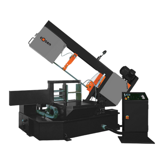
- Page 1 COSEN SAWS SH-700DM Semi‐Automatic Swivel Head Double Mitering Horizontal Bandsaw Instruction Manual The Pinnacle of Cutting Performance Cosen Mechatronics Co., Ltd. ...
- Page 2 ...
- Page 3 FROM THE MANUFACTURER Thank you for your purchase of COSEN’s bandsaw machine and your trust in the COSEN brand. We are excited to have you as our valued customer and look forward as much as you do to the accelerated productivity, long‐lasting endurance and superb cost‐effectiveness this machine is about to bring to you. To ensure you are fully utilizing our machine and being advantaged in every possible way, please do take your time and read through this instruction manual. Any comment or suggestion in making our service better, please do not hesitate to let us know. Thank you again! NOTE: Read this instruction manual carefully to familiarize yourself with the installation, operation and maintenance of your COSEN bandsaw machine. Operate the machine following the procedures described in the manual to prevent personal injuries or machine damage. Keep this manual handy and refer to it whenever you are uncertain of how to perform any of the procedures. For technical support or parts purchase, please contact your nearest COSEN representative or our service center: For US, Mexico, and Canada: For Europe: For China: email: info@cosensaws.com. email: ...
- Page 4 Safety rules Make sure your work area is cleared of uninvited people and obstacles every time before you start operating the machine. Never wear gloves or loose clothing when operating the machine. It may lead to serious injury if they are caught in the running machine. Wrap or cover long hair. Use a water‐soluble cutting fluid on this machine. Oil‐based cutting fluids may emit smoke or catch fire, depending on how they are used. Never cut carbon or any other material that may produce and disperse explosive dust. It is possible that sparks from motors and other machine parts will ignite and explode the air‐borne dust. Make sure any use of fire is prohibited in the shop and install a fire extinguisher or other fire control device near the machine when cutting titanium, magnesium, or any other material that produces flammable chips. Never leave the machine unattended when cutting flammable materials. Never adjust the wire brush or remove chips while the saw blade is still running. It is extremely dangerous if hands or clothing are caught by the running blade. Never touch the running saw blade with gloves or not. It is dangerous if your hands, clothing or gloves are caught by the running blade. Stop the saw blade before you clean the machine. It is dangerous if hands or clothing are caught by the running blade. Never start the saw blade unless the workpiece has been clamped firmly. If the workpiece is not securely clamped, it will be forced out of the vise during cutting. Take preventive measures when cutting thin or short pieces from the work to keep them from falling. It is dangerous if the cut pieces fall. Use roller tables at the front and rear sides of the machine when cutting long work. It is dangerous if the work piece falls off the machine. Never step or stand on the roller table. Your foot may slip or trip on the rollers and you will fall. Turn off the shop circuit breaker switch before performing maintenance on the machine. Post a sign indicating the machine is under maintenance. ...
-
Page 5: Table Of Contents
Table of Contents Safety Information 1‐1 Section 1 – Safety Instructions ……………………………………………………………………………………………………… 1‐1 Safeguard Devices ………………………………………………………………………………………………………. 1‐3 Emergency Stop …………………………………………………………………………………………………………. 1‐4 Illustration: Emergency Stop ……………………………………………………………………………………… 1‐5 Safety Labels ………………………………………………………………………………………………………………. 1‐6 1‐7 Illustration: Safety Labels ………………………………………………………………………………………….. Hearing Protection ……………………………………………………………………………………………………… 1‐8 CE Compliance ……………………………………………………………………………………………………………. 1‐8 Risk Assessment …………………………………………………………………………………………………………. 1‐8 General Information 2‐1 Section 2 – Specifications ……………………………………..………………………………………………………………………. 2‐2 Machine Parts Identification ………………………………………………………………………………………. 2‐3 Floor Plan …………………………………………………………………………………………………..………………. 2‐4 Moving & Installation ... - Page 6 Table of Contents Standard Accessories ………….………………………..……………………………………………….…………… 4‐7 Optional Accessories …….…….………………………..…………………………………………….……………… 4‐9 Unrolling & Installing the Blade …………………………………………………………………….……………. 4‐11 Adjusting Wire Brush ………..……………………………………………………………………….………………. 4‐13 Adjusting Material Depth Bar …………………………………………………………………….……………….. 4‐13 Adjusting Saw Arm ………..……………………………………………………………………….…………………… 4‐14 Adjusting Coolant Flow ………..………..…………………………………………………………………..………. 4‐14 Adjusting Blade Speed ………..………..……………………………………………………………………………. 4‐15 Breaking‐In the Blade ………..………..…………………………………………………………………..…………. 4‐15 Test‐Running the Machine ………..………………..…..…………………………………………………………. 4‐15 Cutting Operation ………..………..……………………………………………..……………………………………. 4‐16 Using Top Clamp for Bundle Cutting ………..……….………………………………………………………… 4‐17 Terminating a Cutting Operation ………..………..…………………………………….………………………. 4‐17 Electrical System 5‐1 Section 5 – Electrical Circuit Diagrams ……….…………………..…………………………………………………………….. 5‐1 Hydraulic System 6‐1 Section 6 – Hydraulic Diagrams ……….…………………..……………………………………………………………….………. 6‐1 Bandsaw Cutting: A Practical Guide ...
- Page 7 Table of Contents Troubleshooting 9‐1 Section 9 – Introduction ……………………….…….…………………..……………………………………………………………. 9‐1 Precautions ………………….…………………..……………………………………………………………………..9‐2 General Troubles & Solutions ………………………..……………………………………………………………. 9‐2 Minor Troubles & Solutions ………………………..………………………………………………..……………. 9‐3 Motor Troubles & Solutions ………………………..…………………………………………………..…………. 9‐3 Blade Troubles & Solutions ………………………..……………………………………………………………….. 9‐4 Sawing Problems & Solutions ………………………..…………………………………………………………… 9‐5 Re‐Adjusting the Roller Table ………………………..……………………………………………………………. 9‐6 Parts 10‐1 Section 10 – Spare Parts Recommendations …………………..………………………………………………………………. 10‐1 Part List …………………..…………………………………………………………………………………………………. 10‐1 Warranty 11‐1 Section 11 – Warranty …………………..……………………………………………………………………………………………….. 11‐1 iii ...
- Page 8 ...
-
Page 9: Section 1 - Safety Information
Section 1 SAFETY INFORMATION SAFETY INSTRUCTIONS SAFEGUARD DEVICES EMERGENCY STOP SAFETY LABELS HEARING PROTECTION CE COMPLIANCE RISK ASSESSMENT Safety is a combination of a well‐designed machine, operator’s knowledge about the machine and alertness at all times. COSEN’s band machine has incorporated many safety measures during the design process and used protective devices to prevent personal injuries and potential risks. Warning labels also serve as a reminder to the operator. Throughout this manual, you will also see various safety‐related symbols indicating important information that you should take note of prior to use of the machine or part of its functions. These important safety instructions do not cover all possible situations that might occur. It is your responsibility to take caution and follow procedures stated in this manual when installing, maintaining and operating your machine. Cosen will not be liable for damages resulting from improper use. SAFETY INSTRUCTIONS What the icons and signs in this user manual mean: This icon marks DANGER; hazards or unsafe practices that may result in severe personal injury or death. This icon marks WARNING; hazards or unsafe practices that may result in personal injury or damage to the machine. This icon marks CAUTION; information that should be read before use to prevent damage to the machine. Supplementary information to the procedures described in this manual. Call your local agent or our service center for help. ... - Page 10 This manual has important safety All users must read it before performing any information. Read through it carefully activity on the machine, such as replacing before operating this machine to prevent the saw band or doing regular maintenance. personal injury or machine damage. Learn the operation, limitation and the specific Some personal protective equipment is potential hazards peculiar to this band required for the safe use of the machine, e.g. protection goggles. saw. Do not operate this machine unless it is Keep blade protection cover and wheel completely assembled. covers in place and in working order. Make sure the power switch is off before Use recommended accessories. Improper plugging in power cord. accessories may be hazardous. Disconnect the power cord before making Keep your work area well illuminated at adjustment, maintenance or blade minimum 500 lumen. changes. Keep your work area clean. Cluttered and Keep all guards and shields in place before slippery floors invite accidents. installing or starting up the machine. Remove adjusting keys, wrenches or any Wear proper apparel during operation loose parts or items from the machine and when servicing the machine. ...
-
Page 11: Safeguard Devices
SAFEGUARD DEVICES The safeguard devices incorporated in this machine include the following two main parts: 1. Protection covers & guards 2. Safety‐related switches Protection Covers & Guards 1. Idle wheel housing cover 2. Drive wheel housing cover 3. Gear reducer cover 4. Wire brush belt cover 5. Blade guard cover (left & right) The protection devices should always be mounted on the machine whenever the machine is running. Do not remove any of these safeguard devices under any circumstances except when servicing the machine. Even skilled service technicians should still take cautions when performing repairs or service on the machine with any of these protectors removed. It is the responsibility of the user to make sure all these elements are not lost and damaged. Take note of the following main moving parts on the machine prior to and during machine operation: Saw bow assembly Drive and idle wheels Blade guide arm Saw blade guide rollers Quick approach device Wire brush Chip conveyor (optional) ... -
Page 12: Emergency Stop
Safety Related Switches To protect the operator, the following safety related switches on the machine are actuated when the machine is in operation. Wheel motion detector This is a proximity sensor used to detect the motion of the drive wheel. Once the saw blade is broken or as soon as it starts slipping, the sensor will detect and stop the drive wheel and the machine. Power switch Located on the cover of electrical cabinet, the power switch controls the main power of the machine. Up to your company’s internal rules, this power switch can be locked with a padlock or a luggage lock to protect the operator and the machine. Emergency stop button Located on the control panel, the button when pressed will stop the machine completely. Vise clamp switch This switch assures firm clamping of the workpiece. If the workpiece is not clamped properly, the saw blade is not allowed to run. Wheel cover interlock switches Located on the two wheel housings, these switches (CE model only) are used to assure that the machine will stop whenever the wheel covers are open. This device is to protect users from being cut by the running saw blades. Among all these safety switches, some of them are used to protect the users and some of them are used to prevent damage to saw blades, the workpiece and the machine itself, etc. We have taken every precaution to prevent injury or damage and to provide safe and economical operation of the machine. EMERGENCY STOP Designed to be easily accessible, the emergency stop button is located on the left bottom corner on the control panel and is made in red color and rubber material. For CE models, supplementary emergency stop button may be available at other area(s) of the machine depending on machine type. ... -
Page 13: Illustration: Emergency Stop
Illustration: Emergency Stop Emergency Stop Button 1‐5... -
Page 14: Safety Labels
SAFETY LABELS Please read through and understand these safety labels before operating the machine. Refer to Illustration: Safety Labels. Label Meaning Label Meaning Impact Hazard Read Operator’s Manual WEAR SAFETY SHOES. Do This manual has important safety not approach dropping area information. Read through it during operation. carefully before operating this machine to prevent personal injury or machine damage. Keep Unauthorized Do not step. Personnel Away Do not stand on the machine or on the accessories! DANGER: Running Blade Cutting Hazard Blade runs through this KEEP COVER CLOSED / KEEP HAND area. Keep your hands away OFF while the blade is running. from a running blade to ... -
Page 15: Illustration: Safety Labels
Illustration: Safety Labels 1‐7... -
Page 16: Hearing Protection
Speed reducer Hydraulic motor/pump Belt transmissions variable speed motors Blade motor Coolant pump Drive wheel Parts not assembled tightly causing mechanical vibration Our products pass noise testing less than 78 dBA. Noise level vary according to working conditions and we recommend ear plugs or other hearing protection at all time. If your machine produces an undesirable noise while it is running, you should: Make sure all maintenance tasks have been performed following the prescribed maintenance schedule (Refer to Section 8). If maintenance does not seem to solve the problem, follow the troubleshooting procedures under Section 9. CE COMPLIANCE Cosen’s CE model is designed to satisfy regulations of the Council Directive on the approximation of the laws of the Member States relating to machinery (2006/42/EC) ‐ Annex I Essential health and safety requirements relating to the design and construction of machinery. RISK ASSESSMENT Risk assessment generally takes account of intended use and foreseeable misuse, including process control and maintenance requirements. We made every effort to avoid any personal injury or equipment damage during the machine design stage. However, the operator (or other people) still needs to take precautions when handling any part of the machine that is unfamiliar and anywhere on the machine that has potential hazards (e.g. the electrical control box). 1‐8 ... -
Page 17: Section 2 - General Information
Section 2 GENERAL INFORMATION SPECIFICATION MACHINE PARTS IDENTIFICATION FLOOR PLAN This band saw machine is designed by Cosen’s R&D engineers to provide you the following features and advantages: Safety This machine is designed to fully protect the operator from its moving parts during cutting operation. The machine and each compoment has passed strict testing (Council Directive on the approximation of the laws of the Member States relating to Machinery). The machine will shut off automatically when the saw blade is broken, protecting both the operator and the machine. Convenience & High‐Performance The machine is designed in the way that the operation and adjustment can be easily performed. The machine will stop automatically when out of stock. Dual valve system is designed to achieve optimal cutting performance with the simple setting of feed rate and perspective cutting pressure for different material. Durability The intended life‐span of the machine is counted based on regular daily operation. It is calculated with the life expectancy of 10 years under normal operating condition and exact attention to the maintenance schedule. 8 hours × 5 days × 52 weeks × 10 years = 20,800 hours 2‐1 ... - Page 18 SPECIFICATION SH‐700DM Model Semi‐Automatic Swivel Head Double Mitering Horizontal Bandsaw 0° +60° ± 45° Angle 450 mm 450 mm 300 mm Round (17.7”) (17.7”) (11.8”) Capacity 450 x 700 mm 450 x 450 mm 300 x 450 mm Rectangular (H x W) (17.7” x 27.5”) (17.7” x 17.7”) (11.8” x 17.7”) W: 710 mm (28”) Bundle Cutting H: 455 mm (17.9”) 20 ~ 100 m/min (66~328 fpm) Speed 5,800 x 41 x 1.3 mm (228” x 1.6” x 0.05”) Size ...
- Page 19 MACHINE PARTS IDENTIFICATION 2‐3...
-
Page 20: Floor Plan
FLOOR PLAN Machine top view 2‐4 ... - Page 21 Machine front view Machine side view 2‐5...
- Page 22 ...
-
Page 23: Section 3 - Moving & Installation
Section 3 MOVING & INSTALLATION LOCATION & ENVIRONMENT UNPACKING & INSPECTING LIFTING REMOVING SHIPPING BRACKET CLEANING INSTALLING RELOCATING LOCATION & ENVIRONMENT For your safety, please read all information regarding installation before proceeding. Install your machine in a place satisfying all of the following conditions: Space: Leave enough free space around the machine for loading work and unloading cut‐off pieces as well as for maintenance and inspection. Refer to Section 2 General Informattion for machine dimensions and floor space. Environment: Well lighted (500 lumen at minimum). Floor kept dry at all times in order to prevent operators from slipping. Away from direct exposure to the sunlight Room temperature between 5˚C to 40˚C. Humidity level kept at 30 ~95%“(without condensation) to avoid dew on electric installation and machine. Away from vibration of other machines Away from powders or dusts emitted from other machines ... -
Page 24: Unpacking & Inspecting
UNPACKING & INSPECTING Unpack your machine carefully to avoid damage to machine parts or surfaces. Upon arrival of your new band saw, please confirm that your machine is the correct model and it comes in the same specification you ordered by checking the model plate on the machine base. It is also imperative that a thorough inspection be undertaken to check for any damage that could have occurred during shipping. Pay special attention to machine surface, equipments furnished and the electrical and hydraulic systems for damaged cords, hoses and fluid leaks. In the event of damage caused during shipping, please contact your dealer and consult about filing a damage claim with the carrier. Your machine comes in with a set of tools for you to maintain the machine. The accessories furnished are as follows: 1. Tool box 1 pc 2. Grease gun 1 pc 3. Screwdriver (+, ‐) 2 pcs 4. Open‐ended spanner ... -
Page 25: Lifting
LIFTING When moving the machine, we strongly suggest you choose any one of the methods described below to move your machine. 1. Use a crane Move the machine to its location by using a crane and a wire rope sling that can fully withstand the weight of the machine (refer to machine specification under Section 2 General Information). Machine lifting is likely to damage the machine if not performed properly. You must have a qualified crane operator to perform the job. You must use tools and equipment with the proper tensile strength and use proper method when moving your machine. Apply the wire rope sling to the lifting hooks on the four ends of the machine. Refer to Illustration: Lifting Points for exact locations. Slowly lift the machine. Be sure to protect the machine from impact or shock during this procedure. Also watch out your own fingers and feet to avoid injuries. Keep the machine well balanced during lifting process and make sure the wire rope does not interfere with the saw frame. When you work together with more than two people, it is best to keep constant verbal ... - Page 26 2. Use a forklift Most users choose this method to move their machine because it is easy to set up. Make sure that the lifting rod can fully withstand the weight of the machine. (Refer to Section 2 – General Information for Specifications) Machine lifting is likely to damage the machine if not performed properly. You must have a qualified forklift operator to perform the job. You must apply proper forklift technique to avoid damage to the machine. Make sure the forks are able to reach in at least 2/3 of the machine depth. You must keep the machine balanced at all times. Make sure the forks are centered before use. (Illustration only.) 3. Use rolling cylinders You can use rolling cylinders to move your machine in a small machine shop environment. You must use rolling cylinders made in material of proper compressive strength. ...
-
Page 27: Illustration: Lifting Points
Illustration: Lifting Points Minimum weight capacity for each wire rope: 2.5 ton Total number of wire ropes required: 4 3‐5... -
Page 28: Removing Shipping Bracket
Retain this bracket so that it can be used again in the event that your machine must be relocated. CLEANING After the machine has been placed at the designated position, remove the rust‐preventive grease with wiping cloth dampened with cleaning oil or kerosene. Apply machine oil to machine surfaces that are prone to rust. Do not remove the rust‐preventive grease with a metal scraper and do not wipe the painted surfaces with solvent as doing so would damage surface paint. INSTALLING Cosen’s bandsaw machine is relatively easy to install. Follow these six easy steps to install your machine. Connect Leveling & Supply Supply Installing roller electric anchoring hydraulic oil cutting fluid table (Optional) power ... -
Page 29: Supplying Coolant
starting the machine. If the coolant pump is started without enough coolant supply in the tank, the pump and its drive motor may be damaged. Refer to specification chart under Section 2 General Information for tank capacity. Consult your coolant supplier for bandsaw use regarding coolant type and mix ratio. Connecting electric power Have a qualified electrician make the electrical connections. If the power supply voltage is different from the transformer and motor connection voltage shown on the label attached to the electrical compartment of the machine, contact COSEN or your agent immediately. Connect to power supply independently and directly. Avoid using the same power supply with electric spark machines such as electric welder. Unstable electric tension may affect your machine’s electric installation from working properly. Ground the machine with an independent grounding conductor. Supply voltage: 90 ‐ 110 of nominal supply voltage. Source frequency: 99 ‐ 101 of nominal frequency. Refer to the specification chart under Section 2 for total electric power consumption of the motors and make sure your shop circuit breaker is capable of this consumption amount. Also use a power supply cable of proper size to suit the power supply voltage. 3‐7... - Page 30 Turn off the shop circuit breaker. Make sure the machine circuit breaker switch on the electrical compartment door is turned to OFF. Remove the screw securing the electrical compartment and then open the door. Pull the power supply cable and grounding conductor through the power supply inlet into the electrical compartment. (Shown right) Connect the power supply cable to the circuit breaker (N.F.B.) to the R, S and T terminals, and connect the ground cable to the E terminal. Close the compartment door and fasten the screw back. Turn on the shop circuit breaker and then turn the machine circuit breaker switch to ON. The Power Indicator on the control panel will come on. Pull to unlock the Emergency Stop button and press the hydraulic ON button to start the hydraulic motor. Make sure the sawing area is clear of any objects. Start the blade and check the blade rotation. If the electrical connections are made correctly, the blade should run in a counterclockwise direction. If not, shut the hydraulics off, turn off the machine as well as the shop circuit breaker. Then swap the power the power cable conductors connected to R and T terminals. 10. Repeat step 6 to 9 to ensure the electrical connections are in the right order. Leveling Place spirit level on the vise slide plates and the work feed table. Level the machine in both directions i.e. along and across the machine. Adjust the level of the machine by turning the leveling bolts. ...
-
Page 31: Installing Roller Table (Optional)
Anchoring the machine Normally there is no need to anchor the machine. If the machine is likely to vibrate, fix the machine to the floor with anchor bolts. Shock absorption steel plates are provided and can be placed under each leveling bolt to prevent their sinking into the concrete floor. Installing roller table (optional) The roller table is used to support long material at the rear and/or the front of the machine. If you have ordered the optional roller table for cutting long material, position it before or behind the machine. Level the roller table and the stand with the Adjust bolts machine by adjusting the leveling bolts. Installing fire control device Install a fire extinguisher or any other fire control device in the shop in case a fire breaks out. RELOCATING We recommend you follow these procedures when relocating or shipping your machine to other place: ... - Page 32 ...
-
Page 33: Operating Instructions
Section 4 OPERATING INSTRUCTION SAFETY PRECAUTIONS BEFORE OPERATING CONTROL PANEL STANDARD ACCESSORIES OPTIONAL ACCESSORIES UNROLLING & INSTALLING THE BLADE ADJUSTING WIRE BRUSH ADJUSTING MATERIAL DEPTH BAR ADJUSTING SAW ARM ADJUSTING COOLANT FLOW ADJUSTING BLADE SPEED BREAKING‐IN THE BLADE TEST‐RUNNING THE MACHINE CUTTING OPERATION USING TOP CLAMP FOR BUNDLE CUTTING TERMINATING A CUTTING OPERATION 4‐1 ... -
Page 34: Safety Precautions
SAFETY PRECAUTIONS For your safety, please read and understand the instruction manual before you operate the machine. The operator should always follow these safety guidelines: The machine should only be used for its designated purpose. Do not wear gloves, neckties, jewelry or loose clothing/hair while operating the machine. For eye protection, always wear protective safety glasses. Check the blade tension and adjust blade guides before starting the machine. Use auxiliary clamping or supporting devices to fix material in place before cutting long workpieces. Always make sure the material is clamped firmly in place before starting to cut. Do not remove jammed or cut‐off pieces until the blade has come to a full stop. Keep fingers away from the path of the blade. Protection devices should be in place at all times. For your own safety, never remove these devices. Disconnect machine from the power source before making repairs or adjustments. Wear protection gloves only when changing the blade. Do not operate the machine while under the influence of drugs, alcohol or medication. Do not take your eyes off the machine while in operation. Do place warning signs to mark out machine work zone and restrict entry to be staff‐only. 4‐2 ... -
Page 35: Before Operating
BEFORE OPERATING Choosing an appropriate saw blade and using the right cutting method is essential to your cutting efficiency and safety. Select a suitable saw blade and cutting method based on your work material and job requirements e.g. cutting accuracy, cutting speed, economic concern, and safety control. Wet cutting If you choose dry cutting or low‐speed cutting, the chips may accumulate in machine parts and may cause operation failure or insulation malfunction. We suggest you choose wet cutting to avoid machine damage. Cutting unknown materials Before cutting an unknown material, consult the material supplier, burn a small amount of chips from the material in a safe place, or follow any other procedure to check if the material is flammable. Never take your eyes off the machine while in operation. Cutting fluid For cooling and lubrication purpose, we recommend you use water‐soluble cutting fluids. The following table lists out its pros and cons for your reference. Pro Con Have a high cooling effect Remove machine paint Not flammable Lose its rust protection effect if Economical deteriorated Does not require cleaning of the cut Tend to create foam Subject to decay products ... -
Page 36: Control Panel
CONTROL PANEL The control panel is located on the top of the electrical box. It includes the following function: power system, hydraulic system, and cooling system. The operator must fully understand the function of each switch and button before operating the machine. 13 14 No. Name No. Name 1 Power indicator lamp 8 Saw bow down button 2 Hydraulic on button 9 Feed forward/backward selector 3 Saw blade start button 10 Coolant on/off switch 4 Emergency stop button 11 Vise clamp/open selector 5 Blade speed indicator 12 Last cut selector 6 Blade speed control knob 13 Cutting pressure control knob 7 ... -
Page 37: Control Buttons
Control Buttons 1. Power indicator lamp When the lamp is on, it indicates the power to the machine is turned on. 2. Hydraulic on button When this button is pressed, the built‐in‐light comes on and the hydraulic pump motor starts to operate. Press emergency stop button to stop the hydraulic system. 3. Saw blade start button When this button is pressed, the built‐in‐light comes on and the blade motor starts to operate. Only if the workbed is at the front end or rear end of the stroke (front limit switch or rear limit switch is actuated), the saw blade start button is available. Make sure the workbed will not be damaged during cutting. Vise has to clamp tightly or the blade motor will not work. Press saw bow up button to stop the blade motor. 4. Emergency stop button Press this button to stop the machine in an emergency. When the button is pressed, it brings the machine to a full stop. The button locks when pressed. In order to unlock it, please turn the button clockwise. 5. Blade speed indicator The blade speed is shown here and the blade speed can be adjusted by blade speed control knob. 6. Blade speed control knob This knob connects with the inverter and the inverter is used to control the rotation speed of the blade motor. The blade speed indicator will show the speed variation while turning this knob. Turn the knob clockwise to increase speed; turn counterclockwise to decrease. 7. - Page 38 While pressing the saw bow up button can stop the running blade, please still make use of the emergency stop button in an emergency. 8. Saw bow down button When this button is pressed, the saw bow descends until the operator lets go of the button. Before lowering the saw bow, the guide arm must be positioned outside the vise in order to avoid hitting the vise and causing damages. 9. Feed forward/backward selector This selector is used to control the motion of the workbed. Turn and hold this selector to the left to move the workbed forward. As soon as the selector is released, the feeding workbed will stop moving forward. Turn and hold this selector to the right to move the workbed backward. As soon as the selector is released, the feeding workbed will stop moving backward. The workbed is able to move only if the saw bow is at the upper limit position. Miter cut direction Selector at Description If the operator wants to miter cut backward, move the workbed forward to avoid from cutting into the workbed. If the operator wants to miter cut forward, move the workbed backward to avoid from cutting into the workbed. 10. Coolant on/off switch Turn this selector to the right to “I” position, the coolant pump will start. Turn this selector to the left to “0” position, the coolant pump will stop. When the saw blade starts running, the coolant pump automatically operates. ...
-
Page 39: Standard Accessories
and the hydraulic power remains “ON.” When the selector is turned to this mode , the saw blade is supposed to cut the material and stop after the lower limit switch is triggered. The saw bow will stay at the lower limit position and the hydraulic power will be “OFF.” The position where the machine stops at after cutting completes can be re‐programmed. When the machine power is on and the hydraulic power is off, simultaneously press the saw bow up button and clamp the vise for 2~3 seconds, the machine will stop at the position where the quick approach sensor is in contact with the quick approach bar. To switch back to stop at the lower limit position, simultaneously press the saw bow down button and clamp the vise for 2~3 seconds when the machine power is on and the hydraulic power is off. 13. Cutting pressure control knob This pressure control knob is used to adjust the cutting pressure of the blade. Turning the knob clockwise increases the cutting pressure. To obtain a good cutting result, choose the right cutting pressure by turning the knob until it points to your material on the color chart. 14. Blade descend speed control knob This knob is used to adjust the descend speed of the saw blade. Turning the knob clockwise increases the blade descend speed. Blade descend speed is a determining factor to a good cutting time and quality cutoff surface. Set the blade descend speed in accordance with the cutting pressure control knob. Also commonly known as the flow control valve. STANDARD ACCESSORIES Blade tension device ... - Page 40 Blade speed/motion detector Besides detecting the blade speed, the speed/motion detector also functions as a safety device. The speed/motion detector protects operators and the machine by preventing blade overloads and consequent damages if a saw blade breaks or skids. Once blade breakage or slippage is detected, the drive wheel will stop in 10 seconds. Inverter This inverter is installed inside the machine base. It is used to control and stabilize the saw blade speed during cutting. To adjust blade speed, use the speed control turn‐knob on the control panel. Note: 1. Make sure the terminal points are connected. 2. Make sure the ambient temperature is within acceptable range and keep the surroundings well ventilated. 3. Keep the inverter away from dust. 4. For repair or maintenance, please contact your local agent. Vibration damper The vibration damper can be assembled to the left saw arm. This accessory is extremely useful in reducing the high‐frequency noise produced when cutting large‐sized material. Quick approach device This device allows the blade to quickly descend to just right above the material to save you operation time. Gear reducer ...
-
Page 41: Optional Accessories
Miter angle scale This band saw machine can miter cut at any degree between 0° to 60°. Miter angles have been preset at the factory. All you need is to swivel the saw bow so the pointer (red arrow) points at the desired angle and lock the handle before cutting. Coolant pump When the hydraulic motor is on, the coolant pump can be individually operated via the control panel. The coolant pump supplies coolant to cool off cutting temperatures during cutting. Also, it can be used to wash off chips. Powered wire brush The wire brush removes the metal chips on the saw blade teeth to so that blade life can be extended. Keep hands away from the transmission shaft and the brush while the wire brush is running. Turn off the hydraulic motor or the main power switch before performing . maintenance or cleaning on the wire brush drive system. OPTIONAL ACCESSORIES Vise pressure regulator This adjustment valve is used to control vise pressure. Pressure Adjust vise pressure based on the material of your workpiece. gauge When cutting pipes or soft materials, reduce vise pressure to prevent ... - Page 42 Top clamp This device is single‐point top clamp used for cutting bundles. Adjustment Open the adjustment valve to adjust the top clamp speed during valve clamping/unclamping. Chip conveyor Chip conveyor is a spiral device to bring chips out during cutting. As a regular maintenance, remove the chip conveyor and clean all chip deposits inside. Projection light Activate the switch to project a beam of light on the work piece. The operator can use the light as reference to adjust the cutting dimension of the work piece. The light will shuts off automatically within 3 minutes. 2M roller table The optional 2M roller table supports the work material and ensures the material be fed in smoothly. Refer to section 9 for further information on adjusting the roller table. 4‐10 ...
-
Page 43: Unrolling & Installing The Blade
UNROLLING & INSTALLING THE BLADE Always wear leather gloves and protection glasses when handling a blade. Unrolling the blade Please follow the procedures illustrated below. Unroll and roll the blade Installing a new blade Step 1 ‐ Select the most suitable saw blade for your workpiece considering the size, shape and material. Step 2 ‐ Turn on the machine power by switching to ON and turn on the hydraulic power. Step 3 ‐ Press the saw bow up button and elevate the saw bow until the right insert holder is clear of the front fixed vise. Step 4 ‐ Turn the tension controller handle from “ ” to “ ” position to release tension. The idle wheel will then move slightly toward the direction of the drive wheel. 4‐11 ... - Page 44 Step 5 ‐ Open the idle and drive wheel cover. Step 6 ‐ Loosen the wire brush assembly fixed nuts and pull the wire brush away from the blade. Step 7 ‐ Loosen the left and right carbide inserts by loosening the “lock nut” shown below. Detach the old blade from below the left and right guide seat and then pull the entire blade out. Step 8 ‐ If necessary, clean the carbide inserts before installing a new saw blade. Step 9 ‐ Place the new blade around the idle wheel and the drive wheel Step 10 ‐ Insert the blade into the left and right tungsten carbide inserts. The back and the sides of the blade need to be touching the inserts as well as the adjacent rollers. Step 11 ‐ Place the blade to the drive wheel and press the back of the blade against the flange of the drive wheel. Step 12 ‐ Make sure the back of the blade is also pressed against the flange of the idle wheel. Step 13 ‐ Turn the tension controller handle to [ ] position to obtain blade tension. Step 14 ‐ Make sure the sides of the blade are in close contact with the carbide inserts and then tighten the left and right carbide inserts by locking the “lock nut.” Step 15 ‐ Gently close the idle and drive wheel covers. Step 16 ‐ Press the saw blade start button to start the blade. Allow the blade to run for a few rotations then press the saw bow up button to elevate the saw bow. Open the wheel covers and make sure the blade has not fallen off the drive and idle wheels. If the blade has shifted, follow the same procedure to reinstall the blade again. Step 17 ‐ Adjust wire brush to a proper position. Refer to Adjusting wire brush in this section. 4‐12 ...
-
Page 45: Adjusting Wire Brush
ADJUSTING WIRE BRUSH Follow these steps to adjust wire brush to appropriate position: Step 1 ‐ Open the drive wheel cover. Step 2 ‐ Adjust the fixed nuts to make brush move up / down until it makes proper contact with the saw blade (see below illustration). Step 3 – Close the drive wheel cover. Proper Improper ADJUSTING MATERIAL DEPTH BAR Depth bar 2 Set screw 3 Set screw 2 Set screw 1 Depth bar 1 Step 1 – Lift the saw bow. Step 2 – Position the material according to your desired cutoff length. Step 3 – Clamp the material securely with vise. Step 4 – Lower the saw bow to allow about 10mm clearance between saw blade teeth edge and the top of the material. Step 5 ‐ Install the depth bar 1 and tighten the set screw 1. Step 6 ‐ Loosen the set screws 2 and 3. Step 7 ‐ Slide and position the depth bar 2 so that the end of depth bar 2 just touches the front of the material. Step 8 ‐ Tighten the set screws 2 and 3. 4‐13 ... -
Page 46: Adjusting Saw Arm
ADJUSTING SAW ARM Adjust the blade guide (guide arm) position based on the size of your workpiece: Step 1 – Loosen the inserts by unlocking the lock nut. Step 2 – Loosen the blade guide locking handle. Then adjust the guide arm to a position suitable for your workpiece size. Step 3 – After adjustment is made, tighten the blade guide lock handle. Step 4 – Clamp the inserts back by locking the lock nut. Blade Guide Lock Handle Inserts Lock Nut ADJUSTING COOLANT FLOW Step 1 – Press the saw blade start button to start the saw blade drive motor. Step 2 – Press the saw bow down button to lower the saw bow. Step 3 – Use the flow control valve (shown below) to adjust the amount of fluid flowing to the cutting area. Adjust the flow amount if you observe the following changes to the chips generated from cutting. If the chips are sharp and curved, increase the coolant flow amount. If the chips are granulated, decrease the coolant flow amount. 4‐14 ... -
Page 47: Adjusting Blade Speed
ADJUSTING BLADE SPEED Step 1 – Set the flow control to “0” position. Step 2 – Press the saw blade start button to start the blade.. Step 3 – Turn the blade speed control knob to adjust the blade speed. The blade speed should be adjusted based on the size and the material of the workpiece. BREAKING‐IN THE BLADE When a new saw blade is used, be sure to first break in the blade before using it for actual, extended operation. Failure to break in the blade will result in less than optimum efficiency. To perform this break‐in operation, the following instructions should be followed: Step 1 ‐ Reduce the blade speed to one‐half of its normal setting. Step 2 ‐ Lengthen the cutting time to 2‐3 times of what is normally required. Step 3 ‐ Start break‐in operation. Step 4 ‐ After the break‐in operation is completed, set all parameters back to normal settings. TEST‐RUNNING THE MACHINE Test‐running this machine can ensure good machine performance in the future. We suggest you run the following tests on the machine before first use: Testing machine performance: Turn on the power and run a basic performance test after you finish installing the machine. Follow these steps to test machine performance: Step 1 – Disassemble shipping brackets and bolts. Step 2 – Install roller table (optional). Step 3 – Turn on the relay switch in the control box. Step 4 – Elevate the saw bow. (If your coolant pump is in reverse and the machine cannot run, please change the electrical phase.) Step 5 – After the saw bow ascends, extend the quick approach device. Step 6 – Remove the rust‐prevention grease with cleaning oil or kerosene. Step 7 – Start the coolant pump. Step 8 – Test these functions under manual mode: vise clamping/unclamping saw bow ascending/descending ... -
Page 48: Cutting Operation
CUTTING OPERATION Step 1 – Check before you cut Power: Check the voltage and frequency of your power source. Coolant: Check if you have sufficient coolant in the tank. Hydraulic: Check if you have sufficient (at least two‐thirds or higher) hydraulic oil. Workbed: Check if there is any object on the feeding bed that may cause interference. Blade: Check the blade teeth and make sure there is no worn out teeth along the blade. Light: Check the work lamp or laser light (optional) and make sure there is sufficient lighting. Roller: Check all the rollers on the front and rear workbed can roll smoothly. Saw bow: Check the saw bow to see if it can be elevated and lowered smoothly. Step 2 – Place your workpiece onto the workbed manually or by using a lifting tool e.g. a crane. Before loading, make sure the vises are opened to at least wider than the width of the workpiece. Step 3 – Position your workpiece. Step 4 – Clamp the workpiece. Step 5 – Turn the cutting pressure control knob to adjust blade cutting pressure according to the material. Step 6 – Adjust blade descend speed control knob to obtain a suitable blade descend speed for your material. Step 7 – Start running the blade. Before you start cutting, check again that there is no other object in the cutting area. Step 8 – While the blade descends, adjust the blade speed if necessary. You can do so by turning the blade speed control knob, clockwise to speed up and counterclockwise to slow down. The blade speed is displayed in the HMI touch screen. Step 9 – Select the proper cutting condition according to different material. Step 10 – After the entire cutting job is completed, elevate the saw bow to the top and open the vises to remove the workpiece. Step 11 – Clean the workbed by removing chips and cutting fluids. Step 12 – Lower the saw bow to a proper position then turn off the power. ... -
Page 49: Using Top Clamp For Bundle Cutting
USING TOP CLAMP FOR BUNDLE CUTTING Step 1 – Connect the top clamp hoses to the pressure joints on the vise hydraulic cylinders. Adjustment valve Step 2 – Position the workpiece for bundle cutting. Note the allowable clamping width and height. (Refer to Section 2 – General Information, Specifications) Proper and improper stacking of workpieces Proper Improper Step 3 – Open the adjustment valve to adjust the top clamp speed during clamping/unclamping. Step 4 – For subsequent cutting procedures, refer to the instructions under manual operation and automatic operation. STOP TERMINATING A CUTTING OPERATION To terminate a cutting operation, press either the saw bow up button or the emergency stop button. The saw blade will stop running when the saw bow up button is pressed. ... - Page 50 ...
-
Page 51: Section 5 - Electrical System
Section 5 ELECTRICAL SYSTEM ELECTRICAL CIRCUIT DIAGRAMS The following are electrical circuit diagrams of the system without power roller tables: 5‐2 Control panel layout 5‐3 Circuit board layout 5‐4 Power supply layout 5‐5 PLC I/O layout The following are electrical circuit diagrams of the system with 2 power roller tables: 5‐6~5‐10 5‐1... - Page 52 張 1030219 鴻 昌...
- Page 53 張 1030219 鴻 昌...
- Page 54 張 1030219 鴻 昌...
- Page 55 張 1030219 鴻 昌...
- Page 60 5-10...
-
Page 61: Section 6 - Hydraulic System
Section 6 HYDRAULIC SYSTEM HYDRAULIC CIRCUIT DIAGRAM 6‐1... -
Page 63: Section 7 - Bandsaw Cutting: A Practical Guide
Section 7 BANDSAW CUTTING: A PRACTICAL GUIDE INTRODUCTION SAW BLADE SELECTION SOME SAWING PRACTICES CUTTING CONDITIONS SETTING INTRODUCTION Our bandsaw machines are designed to be installed with high quality using high speed saw blades for maximizing productivity. To be able to use this kind of high performance bandsaw blade, the machine has to be of rugged design, has high quality saw blade guides, has sufficient motor horse power for high saw band speeds, and has to be able to apply necessary tension to the saw bands. Your machine has all these features to provide a better service for you. The saw blade is guided through the cutting area by roller guides to keep it straight as it comes off the driving wheels. The precision carbide inserted guides then hold the blade securely and accurately throughout the sawing process. The tension of the saw blade is adjusted through the tensioning device on the strong saw bow. The cutting feed and down feed pressure of the blade is regulated automatically by hydraulic regulation. SAW BLADE SELECTION The factors affecting cutting performance are: Type of material Material size and shape Guide spacing Blade selection Blade speed and feed ... - Page 64 Material and its relation to the cutting rate Tooth spacing Tooth Set Fig. 7.1 Description of Band Depending on the hardness of the material the cutting rate will increase or decrease. For example, it takes more time to cut stainless steel than to cut cast iron. The surface conditions will also affect the cutting rate. If there are places on the surface on the material which are hard, a slower blade speed will be required or blade damage may result. It will be slower to cut tubing than to cut solids, because the blade must enter the material twice, and because coolant will not follow the blade as well. Tough or abrasive materials are much harder to cut than their machinability rating would indicate. Tooth spacing is determined by the hardness of the material and its thickness in cross section. Tooth set prevents the blade from binding in the cut. It may be either a "regular set" (also called a "raker set" ) or a "wavy set". The regular or raker set is most common and consists of a pattern of one tooth to the left, one tooth to the right, and one which is straight, or unset. This type of set is generally used where the material to be cut is uniform in size and for contour cutting. Wavy set has groups of teeth set alternately to right and left, forming a wave‐like pattern. This reduces the stress on each individual tooth, making it suitable for cutting thin material or a variety of materials where blade changing is impractical. Wavy set is often used where tooth breakage is a problem. This is shown in Fig. 7.2 as follows: Right Straight Left Regular (raker) Set Wavy Set Fig. 7.2 The Saw Set ...
- Page 65 Material size and shape The optimum material width for a band saw blade is 1 inch wide by 0.35 inch thick and is about 5 inches long. Below this width tooth loading may become excessive and the cutting rate must be reduced. Above this width blade control begins to be lost, as discussed below. Since the blade "sees" only that material it is cutting, the shape of the stock being cut will also affect cutting speeds, particularly if the piece is excessively wide or if it varies in the dimensions being cut. Guide spacing The rigidity of the blade is a function of guide spacing, with rigidity being reduced to the third power as the distance between the guides increases. For example, with guides spaced 2 inches apart, blade deflection might be approximately 0.2. Under the same conditions, but with the guides spaced at 4 inches apart, blade deflection would be approximately 0.8. This is a much simplified version of the formula, because it does not consider band tension or guide design. It is important to recognize, for example that rollers are considered as a pivotal contact. Whereas carbide faces could be considered as anchored supports. A more complete deviation, including band tension and guide design, is included in Roark's handbook, "Formula for stress and strain". Blade selection There are different types of blades available. Please contact a bandsaw blade manufacturer for advice. Blade speed and feed Blade speed is generally limited by vibration and the ability to keep the blade sufficiently cool to avoid dulling the teeth. A blade which is running fast and taking a very light cut will dull quickly because the tips of the teeth will overheat from the rubbing action. If, however, we force the blade teeth deeper into the material, the blade will be less sensitive to heat, because the teeth are cutting more and rubbing less. Tooth form and spacing The selection of a tooth form generally is determined by the material to be cut. There are three general factors to consider: tooth form, style or shape of the teeth; tooth spacing, the number of teeth to the inch; and tooth set, which provides clearance for the body of the blade. Three styles of tooth are shown in Fig. 7.3 below: Fig. 7.3 Three Styles of Tooth 7‐3...
-
Page 66: Some Sawing Practices
SOME SAWING PRACTICES Saw Pitch Selection Sawing “Rules of Thumb”: 1. The thinner the stock, the finer the saw pitch. 2. The thicker the stock, the coarser the saw pitch. 3. The more difficult the stock, the finer the saw pitch. 4. The softer the material , the coarser the saw pitch. Always have at least three teeth in contact with the material being cut. Material Size and Saw Pitch Anytime during the cutting operation, at least three teeth must be in contact with the material being cut. Figure 7.4 shows some sawing practices: SAWING PRACTICES CORRECT INCORRECT several teeth contact work teeth strike sharp edge Coarse teeth clear chips freely Teeth too fine for large solids Three or more teeth on cutting wall Coarse teeth rip on thin wall Fig. 7.4 Some sawing practices 7‐4... - Page 67 Solid Stock: STYLE up to 25 mm (1”) 25‐100mm (1‐4”) 100‐250mm (4‐10”) 8‐10 TPI 6‐8 TPI 3‐4 TPI (Teeth per inch) Structurals: STYLE up to 10 mm (3/8”) 10‐20mm (3/8‐3/4”) above 20mm (3/4”) 10‐8 TPI 8‐10 TPI 6‐8 TPI Solid Bundle: STYLE up to 20 mm (3/4”) 20‐80mm (3/4–3 1/4”) above 80mm (3 1/4”) 8 ‐ 10 TPI 2 ‐ 8 TPI 4 ‐ 6 TPI ...
- Page 68 ...
-
Page 69: Section 8 - Maintenance & Service
Section 8 MAINTENANCE & SERVICE INTRODUCTION BASIC MAINTENANCE MAINTENANCE SCHEDULE BEFORE BEGINNING A DAY’S WORK AFTER ENDING A DAY’S WORK EVERY MONTH EVERY THREE MONTHS EVERY SIX MONTHS STORAGE CONDITIONS TERMINATING THE USE OF MACHINE OIL RECOMMENDATION FOR MAINTENANCE INTRODUCTION For the best performance and longer life of the band saw machine, a maintenance schedule is necessary. Some of the daily maintenance usually takes just a little time but will give remarkable results for the efficient and proper operation of cutting. BASIC MAINTENANCE It is always easy and takes just a little effort to do the basic maintenance. But it always turns out to be a very essential process to assure the long life and efficient operation of the machine. Most of the basic maintenance requires the operator to perform it regularly. 8‐1... - Page 70 MAINTENANCE SCHEDULE We suggest you do the maintenance on schedule. The recommended schedule includes three periods, 1.Daily maintenance. 2.Monthly maintenance. 3. Six months maintenance. Before beginning a day’s work 1. Please check the hydraulic oil level. If oil level volume is below 1/2, please add oil as necessary.(Filling up to 2/3 level is better for system operation.) 2. Please check the cutting fluid level, adding fluid as necessary. If the fluid appears contaminated or deteriorated, drain and replace it. 3. Please check the saw blade to ensure that it is properly positioned on both the drive and idle wheels. 4. Please make sure that the saw blade is properly clamped by the left and right inserts. 5. Please check the wire brush for proper contact with the saw blade. Replace the wire brush if it is worn out. After ending a day’s work Please remove saw chips and clean the machine with discharging the cutting fluid when work has been completed. Do not discharge cutting fluid while the saw blade is operating because it will cause severe injury on operator’s hand. Be sure the saw blade is fully stop, it will be performed after working inspection. Every month Please apply grease to the following points: ...
- Page 71 Every six months 1.Clean the filter of the cutting fluid. 2.Replace the transmission oil for every half of a year(or 1200 hours). Check the sight gauge to ascertain the transmission level. Recommended TRANSMISSION OIL Omala oil HD220 Mobil comp 632 600W Cylinder oil 3.Replace the hydraulic oil. Recommended HYDRAULIC OIL Shell Tellus 27 Mobil DTE OIL light Hydraulic28 STORAGE CONDITIONS Generally, this machine will be stored on the following conditions in future: (1) Turn off the power. (2) Ambient temperature: 5℃ ~ 40℃ (3) Relative humidity: 30%~95% (without condensation) (4) Atmosphere: use a plastic canvas to cover machine to avoid excessive dust, acid fume, corrosive gases and salt. (5) Avoid exposing to direct sunlight or heat rays which can change the environmental temperature. (6) Avoid exposing to abnormal vibration. (7) Must be connected to earth. TERMINATING THE USE OF THE MACHINE ...
- Page 72 OIL RECOMMENDATION FOR MAINTENANCE Item Method Revolution Suggest oil Dovetail guide Keep grease covered. Antirust. Daily Shell R2 Roller bearing Sweep clean and oil with lubricant. Daily SEA #10 Bed roller / surface Sweep clean and oil with lubricant. Daily SEA #10 Nipples of bearing Use grease gun, but not excess. Monthly Shell R2 Blade tension device Use grease gun, but not excess. Monthly Shell R2 Inspect once a week. Change oil of 600 hours of Omala oil HD220 Reducer Regularly using. Change it every year. Mobil Gear 630 ...
-
Page 73: Precautions
Section 9 TROUBLESHOOTING INTRODUCTION PRECAUTIONS GENERAL TROUBLES & SOLUTIONS MINOR TROUBLES & SOLUTIONS MOTOR TROUBLES & SOLUTIONS BLADE TROUBLES & SOLUTIONS SAWING PROBLEMS & SOLUTIONS RE‐ADJUSTING THE ROLLER TABLE INTRODUCTION All the machines manufactured by COSEN pass a 72 hours continuously running test before shipping out and COSEN is responsible for the after sales service problems during the warranty period if the machines are used normally. However, there still exist the some unpredictable problems which may disable the machine from operating. Generally speaking, the system troubles in this machine model can be classified into three types, namely GENERAL TROUBLES, MOTOR TROUBLES and BLADE TROUBLES. Although you may have other troubles which can not be recognized in advance, such as malfunctions due to the limited life‐span of mechanical, electric or hydraulic parts of the machine. COSEN has accumulated enough experiences and technical data to handle all of the regular system troubles. Meanwhile, the engineering department of COSEN had been continuously improving the machines to prevent all possible troubles. It is hoped that you will give COSEN your maintenance experience and ideas so that both sides can achieve the best performance. 9‐1... - Page 74 PRECAUTIONS When an abnormality occurs in the machine during operation, you can do it yourself safely. If you have to stop machine motion immediately for parts exchanging, you should do so according to the following procedures: Press HYDRAULIC MOTOR OFF button or EMERGENCY STOP button. Open the electrical enclosure door. Turn off breaker. BEFORE ANY ADJUSTMENT OR MAINTENANCE OF THE MACHINE, PLEASE MAKE SURE TO TURN OFF THE MACHINE AND DISCONNECT THE POWER SUPPLY. GENERAL TROUBLES AND SOLUTIONS DISCONNECT POWER CORD TO MOTOR BEFORE ATTEMPTING ANY REPAIR OR INSPECTION. TROUBLE PROBABLE CAUSE SUGGESTED REMEDY Excessive belt tension Adjust belt tension so that belt does not slip on drive pulley while cutting ( 1/2“ Min. deflection of belt under moderate pressure.) Excessive head ...
-
Page 75: Minor Troubles & Solutions
MINOR TROUBLES & SOLUTIONS TROUBLE PROBABLE CAUSE SUGGESTED REMEDY Saw blade motor does not run Overload relay activated Reset even though blade drive button Saw blade is not at forward Press SAW FRAME is pressed. limit position. FORWARD button MOTOR TROUBLES & SOLUTIONS TROUBLE PROBABLE CAUSE SUGGESTED REMEDY Magnetic switch open, or Reset protector by pushing red button (inside protector open. electric box.) Motor will not start Low voltage Check power line for proper voltage. Open circuit in motor or loose Inspect all lead terminations on motor for loose connections. or open connections. Short circuit in line, cord or Inspect line, cord and plug for damaged plug. insulation and shorted wire. Motor will not start, Short circuit in motor or loose Inspect all lead terminations on motor for loose fuse or circuit connections ... - Page 76 BLADE TROUBLES AND SOLUTIONS DISCONNECT POWER CORD TO MOTOR BEFORE ATTEMPTING ANY REPAIR OR INSPECTION. TROUBLE PROBABLE CAUSE SUGGESTED REMEDY Too few teeth per inch Use finer tooth blade Loading of gullets Use coarse tooth blade or cutting lubricant. Teeth strippage Excessive feed Decrease feed Work not secured in vise Clamp material securely Teeth too coarse Use a finer tooth blade Misalignment of guides Adjust saw guides Dry cutting Use cutting lubricant Excessive speed Lower speed. See Operating Instructions “Speed Blade selection.” breakage Excessive speed Reduce feed pressure. Refer to Operating Instructions “Adjusting Feed.” Excessive tension Tension blade to prevent slippage on drive wheel while cutting. Wheels out of line Adjust wheels Guides out of line For a straight and true cut, realign guides, check bearings for wear. Excessive pressure Conservative pressure assures long blade life and clean ...
- Page 77 SAWING PROBLEMS AND SOLUTIONS Other than this manual, the manufacturer also provides some related technical documents listed as follows: Sawing Problems and Solutions Vibration during cutting Failure to cut Short life of saw blade Curved cutting Broken blade Use of blade with incorrect pitch Use blade with correct pitch suited to workpiece width Failure to break‐in saw blade Perform break‐in operation Excessive saw blade speed Reduce speed Insufficient saw blade speed Increase speed ...
-
Page 78: Re-Adjusting The Roller Table
RE‐ADJUSTING THE ROLLER TABLE If the feeding table suffers the huge stroke and the alignment is effected, follow the below procedure to adjust. TOOL, measuring Measurement, Horizontal balance Procedure 1. Screw or loosen the adjusting bolt to attain the horizontal balance (leveling) between the roller table and the machine frame. 2. Ensure that the machine frame is not struck by the loaded material on the feeding table. 3. Check the leveling by the measuring tool. 4. After finished the adjusting, fix the roller table. If the feeding table and the machine frame are not positioned under the horizontal balance, the loaded material may be going up gradually and affect the cutting effect. 9‐6... -
Page 79: Section 10 - Parts
Section 10 PARTS SPARE PARTS RECOMMENDATIONS PART LIST SPARE PARTS RECOMMENDATIONS The following table lists the common spare parts we suggest you purchase in advance: Part Name Part Name Saw blade Coolant tank filter Wire brush Steel plates Carbide inserts Rollers Bearings Belt Hydraulic tank leak‐proof asbestos Duster seal Rubber washer Oil seal O‐ring Snap ring Drive wheel Idle wheel 10‐1... - Page 80 PART LIST SH-700DM series S1-20091209 INDEX PART A MACHINE FOUNDATION ASSEMBLY ……………………………………………………….3 PART B BED ASSEMBLY………………………………………………………..…………………………….6 PART C WORK FEED ASSEMBLY……………………….………………………………………………….9 PART D ROTATE THE JOINT ASSEMBLY…………………………………………………………….11 PART D1 HOUSING YOKE CYLINDER ASSEMBLY……………………………………………….14 PART E IDEL WHEEL MOTOR ASSEMBLY…………………….…………………………………….15 PART E1 IDLE WHEEL ASSEMBLY…………………..…………………………………………………….18...
- Page 81 PART LIST SH-700DM series S1-20091209 PART G DRIVE WHEEL MOTOR ASSEMBLY…………..…………………………………………….27 PART H ELECTRIC BOX ASSEMBLY …………………………………..……………………………….29 PART H1 REGULATOR SET ASSEMBLY………………………………………………………………….30 PART H2 FLOW CONTROL VALVE ASSEMBLY……………………………………………………….31 PART I OIL FILTER ASSEMBLY………………………………………………………………………….32 PART J ANTI-VIBRATION ROLLER ASSEMBLY (OPTIONAL)……………………..……….33 PART K PRESS ASSEMBLY (OPTIONAL)………………………………………………………….….35...
- Page 82 PART LIST SH-700DM series S1-20091209 PART A MACHINE FOUNDATION ASSEMBLY 10-3...
- Page 83 PART LIST SH-700DM series S1-20091209 PART A MACHINE FOUNDATION ASSEMBLY ITEM PART NO. PART NAME PART NAME (CH) PART SPEC. COUNT UNIT SEE-1001DM Base seat 底座 AHC-0153 adjusting bolt M20xP2.5x80L 底座調整螺桿 POA-20-25 M20xP2.5 螺母 AHR-1055 base support Ø80xD15 底座墊塊 SEE-1016DM rotate the track 旋轉軌道...
- Page 84 PART LIST SH-700DM series S1-20091209 PART A MACHINE FOUNDATION ASSEMBLY ITEM PART NO. PART NAME PART NAME (CH) PART SPEC. COUNT UNIT PP-21030 fluid level LS-3” 油面計(含固定螺絲螺帽) PP-21030A fluid level LS-3” 水面計(含固定螺絲螺帽) AHA-0108 oil tank washer 油箱蓋防漏石綿 AHA-0102 oil tank cover 油箱蓋...
- Page 85 PART LIST SH-700DM series S1-20091209 PART B BED ASSEMBLY 10-6...
- Page 86 PART LIST SH-700DM series S1-20091209 PART B BED ASSEMBLY ITEM PART NO. PART NAME PART NAME (CH) PART SPEC. COUNT UNIT SEE-2002DM slide the bed 床面滑板 PBA-10-35 bolt M10x35L 有頭內六角螺絲 PAA-8-18 set screw M6xP1.0x18 止付螺絲(公) SEE-1069DM bracket 托架滑塊 SEE-1078DM slippery bracket 托架調整板...
- Page 87 PART LIST SH-700DM series S1-20091209 PART B BED ASSEMBLY ITEM PART NO. PART NAME PART NAME (CH) PART SPEC. COUNT UNIT PPA-10 washer 平面華司(公) PQA-10 spring washer 彈簧華司(公) PBA-10-40 bolt M10x40L 有頭內六角螺絲 PP-13242 bearing 5030 乾式軸承 slippery axle of the SEE-1024 虎鉗滑軸...
- Page 88 PART LIST SH-700DM series S1-20091209 PART C WORK FEED ASSEMBLY PART NO : S700D-12500 10-9...
- Page 89 PART LIST SH-700DM series S1-20091209 PART C WORK FEED ASSEMBLY PART NO : S700D-12500 ITEM PART NO. PART NAME PART NAME (CH) PART SPEC. COUNT UNIT SEE-2013DM roller bracket 床面滾輪座 PPA-10 washer 平面華司(公) PBA-10-15 bolt M10x15L 有頭內六角螺絲 AEE-1004 roller 料架滾輪...
- Page 90 PART LIST SH-700DM series S1-20091209 PART D ROTATE THE JOINT ASSEMBLY 10-11...
- Page 91 PART LIST SH-700DM series S1-20091209 PART D ROTATE THE JOINT ASSEMBLY ITEM PART NO. PART NAME PART NAME (CH) PART SPEC. COUNT UNIT SEE-2010DM regular seat of pivot 轉軸固定座 PP-13259 bearing MB6530 乾式軸承 SEE-1010DM pivot 轉軸 SEE-1020A joint seat 關節座...
- Page 92 PART LIST SH-700DM series S1-20091209 PART D ROTATE THE JOINT ASSEMBLY ITEM PART NO. PART NAME PART NAME (CH) PART SPEC. COUNT UNIT AHA-1105 washer 橡膠墊圈 AGB-70304B pin 下插銷 PP-14480 link bearing POS 18 (M18xP1.5) 連桿軸承 AGB-70304A pin 上鋸弓油缸插銷 AHA-0629 buffer the spring 緩衝彈簧...
- Page 93 PART LIST SH-700DM series S1-20091209 PART D1 HOUSING YOKE CYLINDER ASSEMBLY PART NO : SEE-100500A ITEM PART NO. PART NAME PART NAME (CH) PART SPEC. COUNT UNIT AGC-1024 rear cap 鋸弓油缸後蓋 SEE-1005 piston 鋸弓油缸活塞 PP-59170 o-ring P-70 O 型環 AHA-1117 washer 鐵弗龍墊圈...
- Page 94 PART LIST SH-700DM series S1-20091209 PART E IDEL WHEEL MOTOR ASSEMBLY 10-15...
- Page 95 PART LIST SH-700DM series S1-20091209 PART E IDEL WHEEL MOTOR ASSEMBLY ITEM PART NO. PART NAME PART NAME (CH) PART SPEC. COUNT UNIT SEE-3001DM housing yoke 鋸弓 SEE-1028 joint axle 關節軸 saw and bend the SEE-3015 鋸弓軸套 axle sleeve SEE-1030 joint axle sleeve 關節軸套...
- Page 96 PART LIST SH-700DM series S1-20091209 PART E IDEL WHEEL MOTOR ASSEMBLY ITEM PART NO. PART NAME PART NAME (CH) PART SPEC. COUNT UNIT PPA-5 washer 平面華司(公) PQA-5 spring washer 彈簧華司(公) PBA-5-18 bolt M5 XP0.8x18L 有頭內六角螺絲 AHA-0672 baseplate 感應器底板 AGB-70334A baseplate seat 感應器底板座...
- Page 97 PART LIST SH-700DM series S1-20091209 PART E1 IDLE WHEEL ASSEMBLY PART NO : S700D-30300 ITEM PART NO. PART NAME PART NAME (CH) PART SPEC. COUNT UNIT SEE-3002DM idle wheel 上輪 SEE-3037 wheel shaft 上輪軸 PP-14615 taper roller bearing 30209 滾錐軸承...
- Page 98 PART LIST SH-700DM series S1-20091209 PART E2 TENSION ASSEMBLY PART NO : AGB-703500 ITEM PART NO. PART NAME PART NAME (CH) PART SPEC. COUNT UNIT AGB-70358 tension body 張力滑座 AGB-70359 slide piece 張力滑板 AGB-70360 guide plate 壓板 PPA-8 washer 平面華司...
- Page 99 PART LIST SH-700DM series S1-20091209 PART E3 GEAR BOX ASSEMBLY PART NO : AGB-703109B 10-20...
- Page 100 PART LIST SH-700DM series S1-20091209 PART E3 GEAR BOX ASSEMBLY PART NO : AGB-703109B ITEM PART NO. PART NAME PART NAME (CH) PART SPEC. COUNT UNIT AGB-70309 wheel shaft 下輪軸 PP-14619 taper roller bearing 30211 NSK 軸承 AGB-70313 distance collar 下輪軸承墊圈(一)
- Page 101 PART LIST SH-700DM series S1-20091209 PART F BLADE GUIDE ASSEMBLY 10-22...
- Page 102 PART LIST SH-700DM series S1-20091209 PART F BLADE GUIDE ASSEMBLY ITEM PART NO. PART NAME PART NAME (CH) PART SPEC. COUNT UNIT SEE-3013 guide slide 鋸臂滑板 PBA-10-25 bolt M10x25L 有頭內六角螺絲 PAA-8-20 set screw M8x20L 止付螺絲 C650D-3103 activity guide 活動鋸臂 SEE-3014 slide tip 鋸臂固定塊...
- Page 103 PART LIST SH-700DM 20170109 series S1-20091209 PART F1 LEFT INSERT HOLDER ASSEMBLY PART NO : SGB-710800 ITEM PART NO. PART NAME PART NAME (CH) PART SPEC. COUNT UNIT SGB-71085 left insert holder 左導輪座 EU79 用 AHA-0704A Pressure block 下壓座 AGB-70410A Shaft 軸承座固定軸...
- Page 104 PART LIST SH-700DM 20170109 series S1-20091209 PART F2 RIGHT INSERT HOLDER ASSEMBLY PART NO : SGB-710801 ITEM PART NO. PART NAME PART NAME (CH) PART SPEC. COUNT UNIT SGB-71084 right insert holder 右導輪座 EU79 用 AHA-0704A Pressure block 下壓座 AGB-70410A Shaft 軸承座固定軸...
- Page 105 PART LIST SH-700DM series S1-20091209 PART F3 WIRE BRUSH ASSEMBLY PART NO : S650M-32200 ITEM PART NO. PART NAME PART NAME (CH) PART SPEC. COUNT UNIT MBR-9132-B bearing bracket set 鋼刷軸承座 PP-14250 bushing 6002ZZ 軸承 PP-52097 buckle 扣環 MBR-9129 brush shaft 鋼刷軸...
- Page 106 PART LIST SH-700DM series S1-20091209 PART G DRIVE WHEEL MOTOR ASSEMBLY 10-27...
- Page 107 PART LIST SH-700DM series S1-20091209 PART G DRIVE WHEEL MOTOR ASSEMBLY ITEM PART NO. PART NAME PART NAME (CH) PART SPEC. COUNT UNIT motor base AGB-70340B 鋸弓馬達板(二) plate(二) motor base AGB-70339B 鋸弓馬達底板(一) plate(一) PPA-16 washer 平面華司 PQA-16 spring washer 彈簧華司...
- Page 108 PART LIST SH-700DM series S1-20091209 PART H ELECTRIC BOX ASSEMBLY ITEM PART NO. PART NAME PART NAME (CH) PART SPEC. COUNT UNIT SEE-1303DM electric case base 電氣箱底座 AGB-70801 electric control box 控制箱 PPA-6 washer 平面華司 PQA-6 spring washer 彈簧華司 PBA-6-10 bolt M6xP1.0x10L...
- Page 109 PART LIST SH-700DM series S1-20091209 PART H1 REGULATOR SET ASSEMBLY PART NO : AHA-10289 ITEM PART NO. PART NAME PART NAME (CH) PART SPEC. COUNT UNIT PBA-5-45 bolt M5x45L 有頭內六角螺絲 AHA-1036 rear cap 後蓋 AHA-1030 valve 針閥 AHA-1029 valve seat 閥座...
- Page 110 PART LIST SH-700DM series S1-20091209 PART H2 FLOW CONTROL VALVE ASSEMBLY PART NO : AHA-6100 ITEM PART NO. PART NAME PART NAME (CH) PART SPEC. COUNT UNIT AHA-1039 valve seat 閥座 AHA-1043 valve sleeve 針閥套筒 PP-59071 o-ring P-15 O 形環...
- Page 111 PART LIST SH-700DM series S1-20091209 PART I OIL FILTER ASSEMBLY PART NO : AGB-707270 ITEM PART NO. PART NAME PART NAME (CH) PART SPEC. COUNT UNIT AGB-70727 filter frame 濾油器本體 AGB-70730 filter 濾油器芯 AGB-70729 spring 濾油器彈簧 PP-59531 o-ring G-45 O 形環...
- Page 112 PART LIST SH-700DM 20170109 series S1-20091209 PART J ANTI-VIBRATION ROLLER ASSEMBLY (OPTIONAL) PART NO : AGB-33010C 10-33...
- Page 113 PART LIST SH-700DM series S1-20091209 PART J ANTI-VIBRATION ROLLER ASSEMBLY (OPTIONAL) PART N AGB-33010C O: ITEM PART NO. PART NAME PART NAME (CH) PART SPEC. COUNT UNIT AGB-3303R roller housing 防震座 AGB-3302A anti-vibration roller shaft 防震導輪軸 PP-59085 o-ring O 型環...
- Page 114 PART LIST SH-700DM series S1-20091209 PART K PRESS ASSEMBLY (OPTIONAL) PART N S700D-24000 O: 10-35...
- Page 115 PART LIST SH-700DM series S1-20091209 PART K PRESS ASSEMBLY (OPTIONAL) PART N S700D-24000 O: ITEM PART NO. PART NAME PART NAME (CH) PART SPEC. COUNT UNIT S700D-2405 press the base 下壓底座 PPA-10 washer 平面華司 PQA-10 spring washer 彈簧華司 PBA-10-25 bolt M10xP1.5 x25L...
- Page 116 PART LIST SH-700DM series S1-20091209 PART L CHIP CONVEYOR ASSEMBLY (OPTIONAL) PART NO AEE-C001 : ITEM PART NO. PART NAME PART NAME (CH) PART SPEC. COUNT UNIT AEE-1008 basket 除屑機本體 AHA-2014C rod 除屑螺旋 AHA-2022B shaft 除屑螺旋軸 AGC-1060 motor bracket 除屑馬達座...
- Page 117 10-38...
- Page 118 10-39...
-
Page 119: Section 11 - Warranty
Section 11 Warranty Warranty New machines are warranted to be free from defects in workmanship and material for a period of one (1) year from the date of shipment by Seller. The warranty period is based on normal usage of two thousand eighty hours (2080) per year and is reduced proportionately for any excess usage. Products, which under normal operating conditions in Buyer’s plant are defective in workmanship or material, will be repaired or replaced at the option of Seller. This warranty does not cover shipping freight charges for either the return of the defective part or for the shipping of the replacement or repaired part. Seller will have no obligation to repair or replace perishable parts, or materials or parts damaged by misuse, negligence or failure of Buyer to provide appropriate maintenance and service as stated in the operator’s manual or industry standard and normally acceptable practices. This warranty does not apply if the machine has been altered or modified without our prior written consent. In the case of components or units purchased by Seller including work holding devices, tool holders, motors and controls, the warranty shall not exceed that received by Seller from the supplier of such components or units. Seller will not assume responsibility for products or components returned to Seller without prior consent or for unauthorized repairs to its products, even though defective. Electrical Equipment: The warranty available for all electrical components to the Buyer will be voided if the voltage supplied to the machine is found to be outside the stated voltage of the machine by +/‐ 10% and/or grounded at machine. Accessories Supplied with Manufacturer’s Equipment: The warranties available to the Buyer are those extended by the accessory manufacturer, if any, to the extent they are in force and effect. The ACCESSORY MANUFACTURER’S WARRANTY, if any, is exclusive and is in lieu of all other warranties whether written, oral or implied. 11‐1 ... - Page 120 ...
- Page 121 ...
- Page 122 COSEN SAWS Vertical Plate Saws Horizontal Billet Saws NC/CNC Band Saws Structural Miter‐Cutting Saws Automatic Band Saws Industry 4.0 Cosen Predictive Computing Visit our website at www.cosen.com COSEN MECHATRONICS CO., LTD. ...
Need help?
Do you have a question about the SH-700DM and is the answer not in the manual?
Questions and answers