Table of Contents
Advertisement
Quick Links
S5550
Version 1.0
Copyright
Copyright © 2018 MITAC COMPUTING TECHNOLOGY CORPORATION. All rights
reserved. No part of this manual may be reproduced or translated without prior
written consent from MITAC COMPUTING TECHNOLOGY CORPORATION.
Trademark
All registered and unregistered trademarks and company names contained in this
manual are property of their respective owners including, but not limited to the
following.
®
TYAN
is a trademark of MITAC COMPUTING TECHNOLOGY CORPORATION.
®
®
Intel
is a trademark of Intel
Corporation.
AMI, AMI BIOS are trademarks of AMI Technologies.
Microsoft
®
, Windows
®
are trademarks of Microsoft Corporation.
®
Nuvoton
is a trademark of Nuvoton Technology Corporation.
Notice
Information contained in this document is furnished by MITAC COMPUTING
TECHNOLOGY CORPORATION and has been reviewed for accuracy and reliability
prior to printing. MITAC assumes no liability whatsoever, and disclaims any express
®
or implied warranty, relating to sale and/or use of TYAN
products including liability
or warranties relating to fitness for a particular purpose or merchantability. MITAC
retains the right to make changes to product descriptions and/or specifications at
any time, without notice. In no event will MITAC be held liable for any direct or
indirect, incidental or consequential damage, loss of use, loss of data or other
malady resulting from errors or inaccuracies of information contained in this
document.
1
http://www.tyan.com
Advertisement
Table of Contents

Related Manuals for TYAN S5550


Summary of Contents for TYAN S5550
- Page 1 TECHNOLOGY CORPORATION and has been reviewed for accuracy and reliability prior to printing. MITAC assumes no liability whatsoever, and disclaims any express ® or implied warranty, relating to sale and/or use of TYAN products including liability or warranties relating to fitness for a particular purpose or merchantability. MITAC retains the right to make changes to product descriptions and/or specifications at any time, without notice.
- Page 2 http://www.tyan.com...
-
Page 3: Table Of Contents
3.8 Save & Exit ..................121 Chapter 4: Diagnostics ................123 4.1 Flash Utility ..................123 4.2 AMIBIOS Post Code (Aptio) ............124 Appendix: Fan and Temp Sensors............131 Glossary ....................135 Technical Support .................. 141 http://www.tyan.com... -
Page 4: Before You Begin
1 x S5550 Motherboard 2 x SATA Cable 1 x Rear IO Shield 1 x S5550 Quick reference guide IMPORTANT NOTE: Sales sample may not come with the accessory listed above. Please contact your sales representative to help order accessory for your evaluation. -
Page 5: Chapter 1: Instruction
32 and 64-bit computing, high-bandwidth memory design, and lightning- fast PCI-E bus implementation. The S5550 not only empowers you in today’s demanding IT environment but also offers a smooth path for future application upgradeability. All of these rich feature sets provides the S5550 with the power and flexibility to meet demanding requirements for today’s IT environments. - Page 6 Total (6) 4-pin headers Monitors temperature for CPU & Temperature System Monitoring system environment Monitors voltage for CPU, memory, Voltage chipset & power supply Others Watchdog timer support Onboard Chipset Onboard Aspeed AST2500 Server Management AST2500 iKVM 24-bit high quality video http://www.tyan.com...
- Page 7 Humidity RoHS RoHS 6/6 Compliant Please refer to our AVL support Operating System OS supported list lists. Motherboard (1) S5550 Motherboard Manual (1) Quick Installation Guide Package Contains I/O Shield (1) I/O Shield Cable SATA (2) SATA signal cables TYAN S5550 (S5550GM4NR)
- Page 8 (2) USB3.1 Gen1 ports (via Cable) (2) headers Input /Output (1) D-Sub 15-pin VGA port (at rear) RJ-45 (4) GbE ports, (1) Dedicated for IPMI SATA (6) SATA-III connectors Please refer to our TPM supported TPM (Optional) TPM Support list. http://www.tyan.com...
- Page 9 Humidity RoHS RoHS 6/6 Compliant Please refer to our AVL support Operating System OS supported list lists. Motherboard (1) S5550 Motherboard Manual (1) Quick Installation Guide Package Contains I/O Shield (1) I/O Shield Cable SATA (2) SATA signal cables http://www.tyan.com...
- Page 10 TYAN S5550 (S5550AGM2NR-EX) Q'ty / Socket Type (1) LGA1151 Intel Xeon E-2100 series processors, 8th Gen. Intel Core i3 Supported CPU processors, Intel Celeron G4900 Processor Series Series Processors and Intel Pentium Processor G5000 Series Thermal Design Max up to 95W...
- Page 11 Server Management 2.0 virtual hub IPMI 2.0 compliant baseboard AST2500 IPMI management controller (BMC), Feature 10/100/1000 Mb/s MAC interface Brand / ROM size AMI, 32MB Hardware Monitor, PXE boot BIOS Feature support, ACPI sleeping states S3,S4,S5, User Configurable FAN http://www.tyan.com...
- Page 12 Regulation CE (DoC) Class A Please refer to our AVL support Operating System OS supported list lists. Motherboard (1) S5550 Motherboard Manual (1) Quick Installation Guide Package Contains I/O Shield (1) I/O Shield Cable SATA (2) SATA signal cables TYAN S5550 (S5550AGM4NR-EX)
- Page 13 (2) headers (1) D-Sub 15-pin VGA port (at rear) (4) GbE ports, Input /Output RJ-45 (1) Dedicated for IPMI (1) 2x5-pin header, Audio (1) 3 holes Audio Jack connector SATA (8) SATA-III connectors Display port (2) Display ports 1.2 http://www.tyan.com...
- Page 14 In/Non-operating 90%, non-condensing at 35° C Humidity RoHS RoHS 6/6 Compliant Please refer to our AVL support Operating System OS supported list lists. Motherboard (1) S5550 Motherboard Package Contains Manual (1) Quick Installation Guide I/O Shield (1) I/O Shield http://www.tyan.com...
-
Page 15: Software Specifications
Cable SATA (2) SATA signal cables S5550 SKU Differences SKU Name S5550AGM4NR-EX S5550AGM2NR-EX S5550GM4NR S5550GM2NR SATA Display Port I210 LAN Audio 1.3 Software Specifications ® For OS (operation system) support, please check with TYAN support for latest information. http://www.tyan.com... - Page 16 NOTE http://www.tyan.com...
-
Page 17: Chapter 2: Board Installation
Caution! To avoid damaging the motherboard and associated components, use torque force within the range kgf/cm (4.35 ~ 6.09 lb/in) on each mounting screw for motherboard installation. Do not apply power to the board if it has been damaged. http://www.tyan.com... -
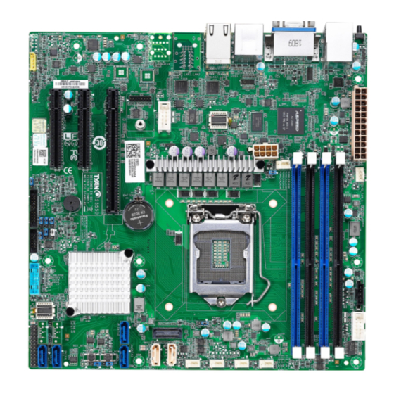
Page 18: Board Image
2.1 Board Image S5550AGM4NR-EX This picture is representative of the latest board revision available at the time of publishing. The board you receive may not look exactly like the above picture. http://www.tyan.com... - Page 19 S5550AGM2NR-EX http://www.tyan.com...
- Page 20 S5550GM4NR http://www.tyan.com...
- Page 21 S5550GM2NR http://www.tyan.com...
-
Page 22: Block Diagram
2.2 Block Diagram S5550 Block Diagram http://www.tyan.com... -
Page 23: Mainboard Mechanical Drawing
2.3 Mainboard Mechanical Drawing http://www.tyan.com... -
Page 24: Board Parts, Jumpers And Connectors
The board you receive may not look exactly like the above diagram. But for the DIMM number please refer to the above placement for memory installation. For the latest board revision, please visit our web site at http://www.tyan.com. http://www.tyan.com... - Page 25 40 BMC Debug (J26) Jumpers Slots Intruder Pin Header (J33) PCIE#1 (J53) Clear CMOS (J12) PCIE#2 (J54) ME Firmware Update (J10) PCIE#3 (J55) Jumper Legend OPEN - Jumper OFF Without jumper cover CLOSED - Jumper ON With jumper cover http://www.tyan.com...
- Page 26 J37: SYS_FAN_5 J38: SYS_FAN_2 J40: SYS_FAN_3 J32: Front Panel Header Signal Signal PWR_LED+ FP_PWR ID_LED+ PWR_LED- ID_LED- HDD_LED+ FAULT_LED1- HDD_LED- FAULT_LED2- PWR_SW# LAN1 ACTLED+ LAN1 ACTLED- RST_SW# SMBus SDA SMBus SCL SYS_ID_SW# INTRUSION# TEMP_SENSOR LAN2 ACTLED+ NMI_SW# LAN2 ACTLED- http://www.tyan.com...
- Page 27 P1_RX_P P0_TX_N P0_TX_P P1_TX_N P1_TX_P P0_N P0_P P1_N OC_N P1_P J15 / J17 / J20 / J21 / J22 / J23: 7-pin Vertical SATA3.0 Connector PIN Define Connects to the Serial ATA ready drives via the Serial ATA cable. http://www.tyan.com...
- Page 28 SD1/SDO1 SDO0 SLOAD SCLOCK V3AUX HDD_FAULT J50: PSMI Connector Signal Signal PSMI_CLK PSMI_DAT PSMI_ALERT J31: IPMB Pin Header Signal Signal IPMB_DATA IPMB_CLK DBG_HD1: TPM Header Signal Signal P3V3 LPC_FRAME_N LPC_LAD0 LPC_LAD1 PLTRST_N LPC_LAD2 LPC_LAD3 IRQ_SERIAL FM_TPM_MOD_PRES_N P3V3_AUX P3V3(NI)/GND RST_ESPI_RESET_N http://www.tyan.com...
- Page 29 3. Move the jumper cap to close Pin_1 and Pin_2 for several seconds to Clear CMOS. 4. Put jumper cap back to Pin_2 and Pin_3 (Default setting). 5. Reconnect power connectors to the motherboard and power on Clear TRC system. http://www.tyan.com...
- Page 30 J10: ME Firmware Update Jumper Pin 1-2 Closed: Normal (Default) Pin 2-3 Closed: ME Force Update http://www.tyan.com...
-
Page 31: Installing The Processor And Heat Sink
NOTE: MITAC TYAN is not liable for damage as a result of operating an unsupported configuration. Processor Installation (LGA1151) Follow the steps below to install the processors and heat sinks. Please note that the illustrations are based on LGA1151 CPU socket which may not look exactly like the motherboard you purchased. - Page 32 Open the CPU socket cover. Install the processor and make sure the gold arrow is located in the right direction. Close the CPU socket cover. Close the socket lever. http://www.tyan.com...
- Page 33 The following diagram illustrates how to install the heat sink. Apply the thermal grease. Place the heat sink on top of the CPU and push the 4 latches in a diagonal pattern to lock it in place. http://www.tyan.com...
- Page 34 Secure the heat sink screws. Connect the fan cable to complete the installation. http://www.tyan.com...
-
Page 35: Thermal Interface Material
CPU lid (applying too much will actually reduce the cooling). NOTE: Always check with the manufacturer of the heat sink & processor to ensure that the thermal interface material is compatible with the processor and meets the manufacturer’s warranty requirements. http://www.tyan.com... -
Page 36: Tips On Installing Motherboard In Chassis
Some chassis include plastic studs instead of metal. Although the plastic studs are usable, MITAC recommends using metal studs with screws that will fasten the motherboard more securely in place. Below is a chart detailing what the most common motherboard studs look like and how they should be installed. http://www.tyan.com... - Page 37 http://www.tyan.com...
-
Page 38: Installing The Memory
2.8 Installing the Memory Before installing memory, ensure that the memory you have is compatible with the motherboard and processor. Check the TYAN Web site at http://www.tyan.com details of the type of memory recommended for your motherboard. Supports up to 64GB of ECC... - Page 39 1. Supported DDR4 (ECC and Non-ECC) UDIMM. 2. The memory slots of DDR4 channels should be populated on a farthest first fashion. This means that blue connector cannot be populated if black is empty. indicates a populated DIMM slot. http://www.tyan.com...
- Page 40 Memory Installation Procedure Follow these instructions to install memory modules into the S5550. Unlock the clips as shown in the illustration. Insert the memory module firmly into the socket by gently pressing down until it sits flush with the socket.
-
Page 41: Attaching Drive Cables
2.9 Attaching Drive Cables Attaching Serial ATA Cables S5550 is equipped with six (6) or eight (8) SATA Channels, depending on the SKU. S5550 SKU Differences SKU Name S5550AGM4NR-EX S5550AGM2NR-EX S5550GM4NR S5550GM2NR SATA Connections for the drives are very simple. -
Page 42: Installing Add-In Cards
Doing so allows air to circulate within the chassis more easily, thus improving cooling for all installed devices. NOTE: You must always unplug the power connector to the motherboard before performing system hardware changes to avoid damaging the board or expansion device. http://www.tyan.com... -
Page 43: Connecting External Devices
(or off) the system. The implementation is convenient to onsite service technicians that need to press the power button when he/she is at the rear side of the system. http://www.tyan.com... - Page 44 The chart below illustrates the different LED states. 10/100/1000 Mbps LAN Link/Activity LED Scheme Left LED Right LED Link Green 10 Mbps Active Blinking Green Link Green Green 100 Mbps Active Blinking Green Green Link Green Amber 1000 Mbps Active Blinking Green Amber No Link http://www.tyan.com...
-
Page 45: Installing The Power Supply
2.12 Installing the Power Supply There are two (2) power connectors on your S5550 motherboard. The S5550 supports EPS 12V power supply. PWR1: 24-pin Power Connector (PW1) Signal Signal +3.3 Vdc +3.3 Vdc +3.3 Vdc -12 Vdc +5 Vdc PS_ON#... -
Page 46: Finishing Up
In the rare circumstance that you have experienced difficulty, you can find help by asking your vendor for assistance. If they are not available for assistance, please find setup information and documentation online at our website or by calling your vendor’s support line. http://www.tyan.com... -
Page 47: Chapter 3: Bios Setup
The table below shows how to navigate in the setup program using the keyboard. Function Left/Right Arrow Keys Change from one menu to the next Up/Down Arrow Keys Move between selections Enter Open highlighted section PgUp/PgDn Keys Change pages Change options Exit http://www.tyan.com... - Page 48 The following pages provide the details of BIOS menu. Please be noticed that the BIOS menu are continually changing due to the BIOS updating. The BIOS menu provided are the most updated ones when this manual is written. Please visit TYAN’s website at http://www.tyan.com for the information of BIOS updating. http://www.tyan.com...
-
Page 49: Main Menu
This displays the total memory size. System Date Set the Date. Use Tab to switch between Date elements. Default Ranges: Year: 2010-2079 Months: 1-12 Days: dependent on month System Time Set the Time. Use Tab to switch between Time elements. Access Level Read only. http://www.tyan.com... -
Page 50: Advanced Menu
This section facilitates configuring advanced BIOS options for your system. iSCSI Configuration Configure the iSCSI parameters. Option ROM Dispatch Policy Option ROM Dispatch Policy. Trusted Computing Trusted Computing Settings. CPU Configuration CPU Configuration Parameters. Server ME Configuration Server ME Configuration. ACPI Settings System ACPI Parameters. http://www.tyan.com... - Page 51 USB Configuration USB Configuration Parameters. Onboard Device Configuration Onboard Device Configuration. S5 RTC Wake Settings Enable system to wake from S5 using RTC alarm. Super IO Configuration System Super IO Chip Parameters. Hardware Health Configuration Hardware health Configuration Parameters. http://www.tyan.com...
- Page 52 Advanced > Option ROM Dispatch Policy >> Onboard Lan1 Option ROM type [iSCSI] Step 2. Network Stack Configuration Settings: Set Advanced > Network Stack Configuration >> Network Stack [Enabled] Step 3. CSM Configuration Settings: Set Advanced > CSM Configuration >> CSM Support [Disabled] http://www.tyan.com...
- Page 53 Enter to “Add an Attempt”. Step 8. Enter to a Device (Ex: MAC A0:42:3F:3A:E4:B4) Step 9. Set Configuration items. iSCSI Initiator Name The worldwide unique name of iSCSI Initiator. Only IQN format is accepted. Enter [iqn.xxx]. xxx ranges from 4 to 223. http://www.tyan.com...
- Page 54 3.3.1.1 Add an Attempt Read only. This MAC address is for iSCSI and subject to change. NOTE: Only LAN1 supports iSCSI function. http://www.tyan.com...
- Page 55 IP4 / IP6 / Autoconfigure Connection Retry Count The minimum value is 0 and the maximum is 16. 0 means no retry. Connection Establishing Timeout The timeout value in milliseconds. The minimum value is 100 milliseconds and the maximum is 20 seconds. http://www.tyan.com...
- Page 56 Target Port Target Port. Boot LUN Hexadecimal representation of the LU number. Examples are: 4752-3A4F-6b7e- 3F99, 6734-9-156f-127, 4186-9. Authentication Type Authentication method: CHAP, Kerberos, or None. CHAP / None Save Changes Must reboot system manually for changes to take place. http://www.tyan.com...
- Page 57 3.3.1.2 Delete Attempts Commit Changes and Exit Commit Changes and Exit. Discard Changes and Exit Discard Changes and Exit. http://www.tyan.com...
- Page 58 3.3.1.3 Change Attempt Order Commit Changes and Exit Commit Changes and Exit. Discard Changes and Exit Discard Changes and Exit. http://www.tyan.com...
- Page 59 Enable or disable onboard LAN2 Option ROM. Disabled / Enabled Onboard LAN3 (I210) (only for -4N SKU) Enable or disable onboard LAN3 Option ROM. Disabled / Enabled Onboard LAN4 (I210) (only for -4N SKU) Enable or disable onboard LAN4 Option ROM. Disabled / Enabled http://www.tyan.com...
- Page 60 PCIE#1 Not Found ~ PCIE#3 Not Found Enable or Disable Option ROM execution for selected Slot. Disabled / Enabled http://www.tyan.com...
- Page 61 3.3.3 Trusted Computing Security Device Support Enables or Disables BIOS support for security device. O.S. will not show Security Device. TCG EFI protocol and INT1A interface will not be available. Enabled / Disabled http://www.tyan.com...
- Page 62 Schedule an operation for the Security Device. NOTE: Your Computer will reboot during restart in order to change State of Security Device. None / TPM Clear Platform Hierarchy Enable or Disable Platform Hierarchy. Disabled / Enabled Storage Hierarchy Enable or Disable Storage Hierarchy. Disabled / Enabled http://www.tyan.com...
- Page 63 TPM 1.2 will restrict support to TPM 1.2 devices. TPM 2.0 will restrict support to TPM 2.0 devices. Auto will support both with the default set to TPM 2.0 devices if not found. TPM 1.2 devices will be enumerated. TPM 1.2 / TPM 2.0 / Auto http://www.tyan.com...
- Page 64 Number of cores to enable in each processor package. All / 1 / 2 / 3 / 4 / 5 Intel (VMX) Virtualization Technology When enabled, a VMM can utilize the additional hardware capabilities provided by Vanderpool Technology. Enabled / Disabled http://www.tyan.com...
- Page 65 SGX Launch Control Policy Software Guard Extensions (SGX) Launch Control Policy. Options are: Intel Locked – Select Intel’s Launch Enclave. Unlocked – Enable OS/VMM configuration of Launch Enclave. Locked – Allow owner to configure Launch Enclave. Unlocked / Intel Locked / Locked http://www.tyan.com...
- Page 66 Enable/Disable processor Turbo Mode (requires Intel Speed Step or Intel Speed shift to be available and enabled). Disabled / Enabled Intel(R) Speed Shift Technology Enable/ Disable Intel(R) Speed Shift Technology support. Enabling will expose the OPPC v2 interface to allow for hardware controlled P- states. Disabled / Enabled http://www.tyan.com...
- Page 67 Package C State Limit Maximum Package C State Limit Setting. Cpu Default: Leaves to Factory default value. Auto: Initializes to deepest available Package C State Limit. C0/C1 / C2 / C3 / C6 / C7 / C8 / Cpu Default / Auto http://www.tyan.com...
- Page 68 3.3.5 Server ME Configuration Server ME Configuration Read only. http://www.tyan.com...
- Page 69 Enables or Disables System ability to Hibernate (OS/S4 Sleep State). This option may not be effective with some operating systems. Disabled / Enabled ACPI Sleep State Select the highest ACPI sleep state the system will enter when the SUSPEND button is pressed. Suspend Disabled / S3 (Suspend to RAM) http://www.tyan.com...
- Page 70 Console redirection enable or disable. Disabled / Enabled Legacy Console Redirection Settings Legacy Console redirection settings. Console Redirection Settings The settings specify how the host computer (which the user is using) will exchange data. Both computers should have the same or compatible settings. http://www.tyan.com...
- Page 71 1’s in the data bits is odd. Mark: parity bit is always 1. Space: parity bit is always 0. Mark and Space parity do not allow for error detection. None / Even / Odd / Mark / Space http://www.tyan.com...
- Page 72 On this mode enabled only text will be sent. This is to capture Terminal data. Disabled / Enabled Resolution 100x31 Enable or disable extended terminal resolution. Disabled / Enabled Putty KeyPad Select FunctionKey and KeyPad on Putty. VT100 / LINUX / XTERMR6 / SCO / ESCN / VT400 http://www.tyan.com...
- Page 73 When Bootloader is selected, the Legacy Console Redirection is disabled before booting to legacy OS. When Always Enable is selected, then Legacy Console Redirection is enabled for legacy OS. Default setting for this option is set to Always Enable. Always Enable / BootLoader http://www.tyan.com...
- Page 74 VT-UTF8 / VT100 / VT100+ / ANSI Bits per Second Select serial port transmission speed. The speed must be matched on the other side. Long or noisy lines may require lower speeds. 9600 / 19200 / 57600 / 115200 http://www.tyan.com...
- Page 75 ‘start’ signal can be sent to restart the flow. Hardware flow control uses two wires to send start/stop signal. None / Hardware RTS/CTS / Software Xon/Xoff Data Bits / Parity / Stop Bits Read only. http://www.tyan.com...
- Page 76 Enables or Disables 64bit capable Devices to be Decoded in Above 4G Address Space. Enabled / Disabled SR-IOV Support If system has SR-IOV capable PCIe Device, this option Enables or Disables Single Root ID Virtualization Support. Enabled / Disabled http://www.tyan.com...
- Page 77 Enable Ipv4 HTTP Boot Support. If disabled IPV4 HTTP boot option will not be created. Disabled / Enabled Ipv6 PXE Support Enable Ipv6 PXE Boot Support. If disabled IPV6 PXE boot option will not be created. Disabled / Enabled http://www.tyan.com...
- Page 78 Enable Ipv6 HTTP Boot Support. If disabled IPV6 HTTP boot option will not be created. Disabled / Enabled PXE boot wait time Wait time to press ESC key to abort the PXE boot. Media detect count Number of times presence of media will be checked. http://www.tyan.com...
- Page 79 Network Controls the execution of UEFI and Legacy PXE OpROM. Legacy / UEFI Storage Controls the execution of UEFI and Legacy Storage OpROM. Legacy / UEFI Video Controls the execution of UEFI and Legacy Video OpROM Legacy / UEFI http://www.tyan.com...
- Page 80 Other PCI Devices Determines OpROM execution policy for devices other than Network, Storage, or Video. Legacy / UEFI http://www.tyan.com...
- Page 81 USB Mass Storage Driver Support Enable/Disable USB Mass Storage Driver Support. Enabled / Disabled Port 60/64 Emulation Enables I/O Port 60h/64h emulation support. This should be enabled for the complete USB keyboard legacy support for non-USB aware OSes. Enabled / Disabled http://www.tyan.com...
- Page 82 Maximum time the device will take before it properly reports itself to the Host Controller. ‘AUTO’ uses default value: for a Root port it is 100 ms, for a Hub port the delay is taken from Hub descriptor. Auto / Manual http://www.tyan.com...
- Page 83 (only for -4N SKU LAN Enable/Disable control function. Disabled / Enabled Chassis Intrusion Detection Enabled: when a chassis open event is detected, the BIOS will record the event. Disabled / Enabled NMI Button Enable or Disable NMI button. Disabled / Enabled http://www.tyan.com...
- Page 84 Disabled / Fixed Time / Dynamic Time Wake system from S5 (when set to [Fixed time]) Wake up hour Select 0-23. For example enter 3 for 3am and 15 for 3pm. Wake up minute Select 0-59. Wake up second Select 0-59. http://www.tyan.com...
- Page 85 Wake system from S5 (when set to [Dynamic time]) Wake up minute increase Select 1-5. http://www.tyan.com...
- Page 86 3.3.14 Super IO Configuration Super IO Chip Read only. http://www.tyan.com...
- Page 87 / IO=3F8h, IRQ=3, 4, 5, 6, 7, 10, 11, 12; / IO=2F8h; IRQ=3, 4, 5, 6, 7, 10, 11, 12; / IO=3E8h, IRQ=3, 4, 5, 6, 7, 10, 11, 12; / IO=2E8h, IRQ=3, 4, 5, 6, 7, 10, 11, 12; http://www.tyan.com...
- Page 88 3.3.15 Hardware Health Configuration Fan Speed Control Fan Speed Control. Manual /Full Speed PWM Minimum Duty Cycle (%) PWM Minimum Duty Cycle (%). BMC Alert Beep Enable / Disable BMC Alert Beep. On / Off PMBus Support PMBus Support. Disabled / Enabled http://www.tyan.com...
- Page 89 3.3.15.1 Sensor Data Register Monitoring Read only. http://www.tyan.com...
-
Page 90: Chipset Menu
3.4 Chipset Menu North Bridge System Agent (SA) Parameters. South Bridge South Bridge Parameters. http://www.tyan.com... - Page 91 3.4.1 North Bridge Configuration Memory Configuration Memory Configuration Parameters. Graphics Configuration Graphics Configuration. DMI/OPI Configuration Control various DMI functions. PEG Port Configuration PEG Port Options. VT-d VT-d capability. Enabled / Disabled http://www.tyan.com...
- Page 92 3.4.1.1 Memory Configuration Submenu Maximum Memory Frequency Maximum Memory Frequency selections in Mhz. Valid values should match the refclk, i.e. devide by 133 or 100. Auto / 2133 / 2400 / 2666 ECC Support Enable/disable DDR ECC support. Enabled / Disabled http://www.tyan.com...
- Page 93 3.4.1.2 Graphics Configuration Submenu Primary Display Select which Graphics device should be Primary Display. Auto / IGFX / PEG / PCH PCIe Internal Graphics (only for -EX SKU) Keep IGFX enabled based on the setup options. Auto / Disabled / Enabled http://www.tyan.com...
- Page 94 DMI Max Link Speed Set DMI Speed Gen1/Gen2/Gen3. Auto / Gen1 / Gen2 / Gen3 DMI Link ASPM Control Enable/Disable the control of Active State Power Management on SA side of the DMI Link. Disabled / L0s / L1 / L0sL1 http://www.tyan.com...
- Page 95 Auto / Force x1 / Force x2 / Force x4 / Force x8 ASPM Control ASPM support for the PEG 0. This has no effect if PEG is not the currently active device. Disabled / Auto / ASPM L0s / ASPM L1 / ASPM L0sL1 http://www.tyan.com...
- Page 96 Select PEG0 Max Payload Size; Choose Auto (Default Device Capability) or force to 128/256 Bytes. Auto / 128 / 256 TLP PEG1 Max Payload size Select PEG1 Max Payload Size; Choose Auto (Default Device Capability) or force to 128/256 Bytes. Auto / 128 / 256 TLP http://www.tyan.com...
- Page 97 PCI Express Configuration settings. DeepSx Power Policies Configure the DeepSx Mode configuration. Disabled / Enabled in S4-S5 Restore AC Power Loss Select AC power state when power is re-applied after a power failure. Power Off / Power On / Last State http://www.tyan.com...
- Page 98 (only for -EX SKU) Read only. Hot Plug Designates this port as Hot Pluggable. Disabled / Enabled SATA Device Type Identify the SATA port is connected to Solid State Drive or Hard Disk Drive. Hard Disk Drive / Solid State Drive http://www.tyan.com...
- Page 99 3.4.2.2 HD Audio Configuration Submenu (only for -EX SKU) HD Audio Control Detection of the HD-Audio device. Disabled = HDA will be unconditionally disabled Enabled = HDA will be unconditionally enabled Enabled / Disabled Audio DSP Enable/Disable Audio DSP. Enabled / Disabled http://www.tyan.com...
- Page 100 The control of Active State Power Management of the DMI Link. Auto / Disabled / L0s / L1 / L0sL1 PCI Express Root Port 1 / 9 / 21 / 22 / 23 / 24 PCI Express Root Port Settings. http://www.tyan.com...
- Page 101 DISABLE – Disables ASPM Disabled / L0s / L1 / L0sL1 / Auto L1 Substates PCI Express L1 Substates settings. Disabled / L1.1 / L1.1 & L1.2 PCIe Speed Configure PCIe Speed. Auto / Gen1 / Gen2 / Gen3 http://www.tyan.com...
-
Page 102: Server Management
OS Watchdog Timer If enabled, starts a BIOS timer which can only be shut off by Management Software after the OS loads. Helps determine that the OS successfully loaded or follows the OS Boot Watchdog Timer policy. Enabled / Disabled http://www.tyan.com... - Page 103 Do Nothing / Reset / Power Down / Power Cycle BMC Logo Enable or Disable BMC Logo. Enabled / Disabled System Event Log Press <Enter> to change the SEL event log configuration. BMC network configuration Configure BMC network parameters. http://www.tyan.com...
- Page 104 Choose options for reactions to a full SEL. Do Nothing / Erase Immediately Log EFI Status Codes Disable the logging of EFI Status Codes or log only error code or only progress code or both. Disabled / Both / Error Code / Progress Code http://www.tyan.com...
- Page 105 Enable/Disable BMC Share Nic. Enabled / Disabled Configuration Address Source Select the configure LAN channel parameters statically or dynamically (by BIOS or BMC). Unspecified option will not modify any BMC network parameters during BIOS phase. Unspecified / Static / DynamicBmcDhcp / DynamicBmcNonDhcp http://www.tyan.com...
- Page 106 Enable or Disable LAN1 IPV6 Support. Enabled / Disabled Configuration Address Source Select the configure LAN channel parameters statically or dynamically (by BIOS or BMC). Unspecified option will not modify any BMC network parameters during BIOS phase. Unspecified / Static / DynamicBmcDhcp http://www.tyan.com...
-
Page 107: Security
Set user password in the Create New Password window. After you key in the password, the Confirm New Password window will pop out to ask for confirmation. Security Frozen Mode Enable or disable HDD security freeze lock. Disable to support secure erase function. Disabled / Enabled Secure Boot Customizable Secure Boot settings. http://www.tyan.com... - Page 108 Restore Factory Keys Force System to User Mode. Install factory default Secure Boot key databases. Reset to Setup Mode Delete all Secure Boot key databases from NVRAM. Key Management Enables expert users to modify Secure Boot Policy variables without full authentication. http://www.tyan.com...
- Page 109 3.6.1.1 Restore Factory Keys Submenu Restore Factory Keys Press ‘Yes’ to proceed ‘No’ to cancel. http://www.tyan.com...
- Page 110 3.6.1.2 Reset to Setup Mode Submenu Reset to Setup Mode Deleting all variables will reset the System to Setup Mode. Do you want to proceed? Press ‘Yes’ to proceed or ‘No’ to cancel. http://www.tyan.com...
- Page 111 Copy NVRAM content of Secure Boot variables to files in a root folder on a file system device. Enroll Efi Image Allow the image to run in Secure Boot mode. Enroll SHA256 Hash certificate of a PE image into Authorized Signature Database (db). http://www.tyan.com...
- Page 112 1. Public Key Certificate: a) EFI_SIGNATURE_LIST b) EFI_CERT_X509 (DER) c) EFI_CERT_RSA2048 (bin) d) EFI_CERT_SHAXXX 2. Authenticated UEFI Variable 3. EFI EFI/COFF Image (SHA256) Key source: Factory, External, Mixed Update / Append Forbidden Signatures Enroll Factory Defaults or load certificates from a file: http://www.tyan.com...
- Page 113 Enroll Factory Defaults or load certificates from a file: 1. Public Key Certificate: a) EFI_SIGNATURE_LIST b) EFI_CERT_X509 (DER) c) EFI_CERT_RSA2048 (bin) d) EFI_CERT_SHAXXX 2. Authenticated UEFI Variable 3. EFI PE/COFF Image (SHA256) Key Source: Factory, External, Mixed Update / Append http://www.tyan.com...
-
Page 114: Boot
Number of seconds to wait for setup activation key. 65535 (0xFFFF) means indefinite waiting. Bootup NumLock State Select the keyboard NumLock state. On / Off Quiet Boot Enable or disable Quiet Boot option. Disabled / Enabled Boot Option #1~#6 Sets the system boot order. Device Name / Disabled http://www.tyan.com... - Page 115 Network Device BBS Priorities Set the order of the legacy devices in this group. Add New Boot Option Add a new EFI boot option to the boot order. Delete Boot Option Delete an EFI boot option from the boot order. http://www.tyan.com...
- Page 116 3.7.1 USB Device BBS Priorities Submenu Boot Option #1 Sets the system boot order. Device Name / Disabled http://www.tyan.com...
- Page 117 3.7.2 Hard Drive BBS Priorities Submenu Boot Option #1 Sets the system boot order. Device Name / Disabled http://www.tyan.com...
- Page 118 3.7.3 Network Device BBS Priorities Submenu Boot Option #1 Sets the system boot order. Device Name / Disabled http://www.tyan.com...
- Page 119 3.7.4 Add New Boot Option Submenu Boot Option #1 Sets the system boot order. Device Name / Disabled http://www.tyan.com...
- Page 120 3.7.5 Delete Boot Option Submenu Delete Boot Option Remove an EFI boot option from the boot order. Select one to delete / UEFI: Built-in EFI Shell http://www.tyan.com...
-
Page 121: Save & Exit
Reset system setup without saving any changes. Save Changes Save changes done so far to any of the setup options. Discard Changes Discard changes done so far to any of the setup options. Restore Defaults Restore/Load Default values for all the setup options. http://www.tyan.com... - Page 122 Save as User Defaults Save the changes done so far as User Defaults. Restore User Defaults Restore the User Defaults to all the setup options. http://www.tyan.com...
-
Page 123: Chapter 4: Diagnostics
BIOS flash failure, you must contact your dealer for a replacement BIOS. There are no exceptions. TYAN does not have a policy for replacing BIOS chips directly with end users. In no event will TYAN be held responsible for damages done by the end user. -
Page 124: Amibios Post Code (Aptio)
South Bridge initialization before microcode loading 0x05 OEM initialization before microcode loading 0x06 Microcode loading 0x07 AP initialization after microcode loading 0x08 North Bridge initialization after microcode loading 0x09 South Bridge initialization after microcode loading 0x0A OEM initialization after microcode loading 0x0B Cache initialization http://www.tyan.com... - Page 125 CPU post-memory initialization is started 0x33 CPU post-memory initialization. Cache initialization 0x34 CPU post-memory initialization. Application Processor(s) (AP) initialization 0x35 CPU post-memory initialization. Boot Strap Processor (BSP) selection 0x36 CPU post-memory initialization. System Management Mode(SMM) initialization 0x37 Post-Memory North Bridge initialization is started http://www.tyan.com...
- Page 126 Reserved for future AMI progress codes S3 Resume Error Codes 0xE8 S3 Resume Failed 0xE9 S3 Resume PPI not Found 0xEA S3 Resume Boot Script Error 0xEB S3 OS Wake Error 0xEC – 0xEF Reserved for future AMI error codes http://www.tyan.com...
- Page 127 CPU DXE initialization (CPU module specific) 0x67 CPU DXE initialization (CPU module specific) 0x68 PCI host bridge initialization 0x69 North Bridge DXE initialization is started 0x6A North Bridge DXE SMM initialization is started 0x6B North Bridge DXE initialization (North Bridge module specific) http://www.tyan.com...
- Page 128 USB initialization is started 0x9B USB Reset 0x9C USB Detect 0x9D USB Enable 0x9E -0x9F Reserved for future AMI codes 0xA0 IDE initialization is started 0xA1 IDE Reset 0xA2 IDE Detect 0xA3 IDE Enable 0xA4 SCSI initialization is started http://www.tyan.com...
- Page 129 No Console Output Devices are found 0xD7 No Console Input Devices are found 0xD8 Invalid password 0xD9 Error loading Boot Option (LoadImage returned error) 0xDA Boot Option is failed (StartImage returned error) 0xDB Flash update is failed 0xDC Reset protocol is not available http://www.tyan.com...
- Page 130 System is waking up from the S3 sleep state 0x40 System is waking up from the S4 sleep state 0xAC System has transitioned into ACPI mode. Interrupt controller is in PIC mode. 0xAA System has transitioned into ACPI mode. Interrupt controller is in APIC mode. http://www.tyan.com...
-
Page 131: Appendix: Fan And Temp Sensors
The red mark indicates the sensor. Fan and Temp Sensor Location: Fan Sensor: It is located in the third pin of the fan connector, which detects the fan speed (rpm). Temp Sensor: refer to Figure 1: Sensor Location. They detect the system temperature around. http://www.tyan.com... - Page 132 BIOS Temp Sensor Name Explanation: http://www.tyan.com...
- Page 133 Fan Speed of SYS_FAN_2 SYS_FAN_3 Fan Speed of SYS_FAN_3 SYS_FAN_4 Fan Speed of SYS_FAN_4 SYS_FAN_5 Fan Speed of SYS_FAN_5 SYS_FAN_6 Fan Speed of SYS_FAN_6 SYS_FAN_7 Fan Speed of SYS_FAN_7 SYS_FAN_8 Fan Speed of SYS_FAN_8 SYS_FAN_9 Fan Speed of SYS_FAN_9 http://www.tyan.com...
- Page 134 Fan Speed of SYS_FAN_10 SYS_FAN_11 Fan Speed of SYS_FAN_11 SYS_FAN_12 Fan Speed of SYS_FAN_12 PSU0_Fan Fan Speed of PSU0_Fan PSU1_Fan Fan Speed of PSU1_Fan PSU0_Temp Temperature of PSU0 PSU1_Temp Temperature of PSU1 PSU0_Status Current status of PSU0 PSU1_Status Current status of PSU1 http://www.tyan.com...
-
Page 135: Glossary
(reading to or writing from a disk drive a single time is much faster than doing so repeatedly) there is the possibility of losing your data should the system crash. Information in a buffer is temporarily stored, not permanently saved. http://www.tyan.com... - Page 136 (like soundcards or keyboards) to access the main memory without involving the CPU. This frees up CPU resources for other tasks. As with IRQs, it is vital that you do not double up devices on a single line. Plug-n-Play devices will take care of this for you. http://www.tyan.com...
- Page 137 EEPROM (Electrically Erasable Programmable ROM): also called Flash BIOS, it is a ROM chip which can, unlike normal ROM, be updated. This allows you to keep ® up with changes in the BIOS programs without having to buy a new chip. TYAN ’s BIOS updates can be found at http://www.tyan.com...
- Page 138 PXE (Preboot Execution Environment): one of four components that together make up the Wired for Management 2.0 baseline specification. PXE was designed to define a standard set of preboot protocol services within a client with the goal of allowing networked-based booting to boot using industry standard protocols. http://www.tyan.com...
- Page 139 NVIDIA s (graphics communications processing units) and NVIDIA MCPs (media and processors). application Depending on the , NVIDIA SLI can deliver as much as two times the performance of a single GPU configuration. http://www.tyan.com...
- Page 140 CPUs without damaging the sensitive CPU pins. The CPU is lightly placed in an open ZIF socket, and a lever is pulled down. This shifts the processor over and down, guiding it into the board and locking it into place. http://www.tyan.com...
-
Page 141: Technical Support
(which can have expensive consequences). If these options are not available for you then TYAN can help. Besides designing innovative and quality products for over a decade, TYAN has continuously offered customers service beyond their expectations. - Page 142 (RMA) number. The RMA number Should be prominently displayed on the outside of the shipping carton and the package should be mailed prepaid. TYAN will pay to have the board shipped back to you. Notice for the USA Compliance Information Statement (Declaration of...
Need help?
Do you have a question about the S5550 and is the answer not in the manual?
Questions and answers