Sign In
Upload
Manuals
Brands
Circutor Manuals
Measuring Instruments
M56638
User Manuals: Circutor M56638 Digital Multimeter
Manuals and User Guides for Circutor M56638 Digital Multimeter. We have
2
Circutor M56638 Digital Multimeter manuals available for free PDF download: Instruction Manual
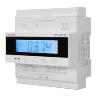
Circutor M56638 Instruction Manual (60 pages)
Power analyzer
Brand:
Circutor
| Category:
Measuring Instruments
| Size: 9 MB
Table of Contents
Safety Precautions
3
Disclaimer
3
Table of Contents
4
Contents
4
Revision Log
6
Symbols
6
1�- Verification Upon Reception
7
2�- Product Description
7
3�- Device Installation
8
3�1�- Prior Recommendations
8
3�2�- Installation
8
3�3�- Device Terminals
9
3�4�- Connection Diagram
10
3�4�1�- Voltage and Current Measurement with Shunt at the Negative Pole of the Installation
11
3�4�3�- Voltage Measurement
12
3�4�4�- Current Measurement with Shunt at the Negative Pole of the Installation
13
3�4�5�- Current Measurement with Shunt at the Positive Pole of the Installation
14
4�- Operation
15
4�1�- Display
15
4�2�- Keyboard Functions
15
4�3�- Leds
16
4�4�- Relay Outputs
16
4�5�- Analog Output
17
4�6�- Digital Inputs
17
4�7�- Display
17
4�7�1�- Maximum & Minimum Values
18
4�7�2�- Totalisers
19
5�- Configuration
20
5�1�- Configuration of the Input
22
5�1�1�- Voltage Display Value
23
5�1�2�- Voltage Measurement Range
23
5�1�3�- Current Display Value
24
5�1�4�- Current Input
24
5�1�5�- Shunt Position
25
5�1�6�- Decimal Point for Displaying Voltage
25
5�1�7�- Save Configuration
25
5�2�- Rs-485 Communications
26
5�2�1�- Modbus Address
27
5�2�2�- Baud Rate
27
5�2�3�- Data Format
28
5�2�4�- Save Configuration
28
5�3�- Analog Output
28
5�3�1�- Type of Output
29
5�3�2�- Analog Output Parameter
30
5�3�3�- Reading for the Start of the Analog Output
30
5�3�4�-Reading for the End of the Analog Output
31
5�3�5�- Save Configuration
31
5�4�- Relay Output 1
32
5�4�1�- Relay Mode
32
5�4�2�- Relay Pulse Duration
33
5�4�3�- Alarm Parameter
33
5�4�4�- Connection Delay
34
5�4�5�- Alarm Value
35
5�4�6�- Hysteresis
35
5�4�7�- Save Configuration
35
5�5�- Relay Output 2
36
5�6�- Configuration of the Display
36
5�6�1�- Login Password
37
5�6�2�- Cyclic Display
38
5�6�3�- Backlight of the Display
38
5�6�4�- Light Alarm
39
5�6�5�-Display Home Screen
39
5�6�6�- Refresh Time
40
5�6�7�- Deleting the Maximum & Minimum Values
40
5�6�8�- Deleting the Electrical Charge Totalisers
41
5�6�9�- Deleting the Energy Totalisers
41
5�6�10�- Save Configuration
42
5�7�- Software Version
42
6�- Rs-485 Communications
43
6�1�- Connections
43
6�2�- Modbus Protocol
44
6�2�1� READING EXAMPLE: FUNCTION 0X01
44
6�2�2� EXAMPLE of OPERATION of the REMOTE CONTROL: FUNCTION 0X05
44
6�3�- Modbus Commands
45
6�3�1�- Measurement Variables and Device Status
45
6�3�2�- Relay Outputs
46
6�3�3�- Digital Inputs
47
6�3�4�- REMOTE CONTROL OUTPUT (Relay Output)
47
6�3�5�- Deleting Values
47
7�- Technical Features
51
8�- Maintenance and Technical Service
54
9�- Guarantee
54
10�- Eu Declaration of Conformity
55
Annex A.- Configuration Menu
58
Advertisement
Circutor M56638 Instruction Manual (56 pages)
Brand:
Circutor
| Category:
Measuring Instruments
| Size: 9 MB
Table of Contents
Safety Precautions
3
Disclaimer
3
Table of Contents
4
Contents
4
Revision Log
6
Symbols
6
1�- Verification Upon Reception
7
2�- Product Description
7
3�- Device Installation
8
3�1�- Prior Recommendations
8
3�2�- Installation
8
3�3�- Device Terminals
9
3�4�- Connection Diagram
10
3�4�1�- Simultaneous Voltage and Current Measurement
10
3�4�2�- Voltage Measurement
11
3�4�3�- Current Measurement
12
4�- Operation
13
4�1�- Display
13
4�2�- Keyboard Functions
13
4�3�- Leds
14
4�4�- Relay Outputs
14
4�5�- Analog Output
15
4�6�- Digital Inputs
15
4�7�- Display
15
4�7�1�- Maximum & Minimum Values
16
4�7�2�- Totalisers
17
5�- Configuration
18
5�1�- Configuration of the Input
20
5�1�1�- Voltage Display Value
20
5�1�2�- Voltage Measurement Range
21
5�1�3�- Current Display Value
21
5�1�4�- Current Input
22
5�1�5�- Decimal Point for Displaying Voltage
22
5�1�6�- Save Configuration
23
5�2�- Rs-485 Communications
23
5�2�1�- Modbus Address
24
5�2�2�- Baud Rate
24
5�2�3�- Data Format
24
5�2�4�- Save Configuration
25
5�3�- Analog Output
25
5�3�1�- Type of Output
26
5�3�2�- Analog Output Parameter
26
5�3�3�- Reading for the Start of the Analog Output
27
5�3�4�-Reading for the End of the Analog Output
27
5�3�5�- Save Configuration
28
5�4�- Relay Output 1
29
5�4�1�- Relay Mode
29
5�4�2�- Relay Pulse Duration
30
5�4�3�- Alarm Parameter
30
5�4�4�- Connection Delay
31
5�4�5�- Alarm Value
31
5�4�6�- Hysteresis
32
5�4�7�- Save Configuration
32
5�5�- Relay Output 2
32
5�6�- Configuration of the Display
33
5�6�1�- Login Password
34
5�6�2�- Cyclic Display
34
5�6�3�- Backlight of the Display
34
5�6�4�- Light Alarm
35
5�6�5�-Display Home Screen
35
5�6�6�- Refresh Time
36
5�6�7�- Deleting the Maximum & Minimum Values
36
5�6�8�- Deleting the Electrical Charge Totalisers
36
5�6�9�- Deleting the Energy Totalisers
37
5�6�10�- Save Configuration
37
5�7�- Software Version
37
6�- Rs-485 Communications
38
6�1�- Connections
38
6�2�- Modbus Protocol
39
6�2�1� READING EXAMPLE: FUNCTION 0X01
39
6�2�2� EXAMPLE of OPERATION of the REMOTE CONTROL: FUNCTION 0X05
39
6�3�- Modbus Commands
40
6�3�1�- Measurement Variables and Device Status
40
6�3�2�- Relay Outputs
41
6�3�3�- Digital Inputs
41
6�3�4�- REMOTE CONTROL OUTPUT (Relay Output)
42
6�3�5�- Deleting Values
42
6�3�6�- Device Configuration Variables
43
7�- Technical Features
46
8�- Maintenance and Technical Service
49
9�- Guarantee
49
10�- Ce Certificate
50
Annex A.- Configuration Menu
53
Advertisement
Related Products
Circutor M566380040000
Circutor M5663A
Circutor M5663A0040000
Circutor M52706
Circutor M527060030000
Circutor M58100
Circutor M224500030000
Circutor M22250
Circutor M222520030000
Circutor MDC-4
Circutor Categories
Measuring Instruments
Relays
Battery Charger
Automobile Accessories
Controller
More Circutor Manuals
Login
Sign In
OR
Sign in with Facebook
Sign in with Google
Upload manual
Upload from disk
Upload from URL