Table of Contents
Advertisement
Quick Links
NuMaker-HMI-MA35D1-S1
NuMicro
®
Family
Arm
Cortex-A35-based Microprocessor
®
NuMaker-HMI-MA35D1-S1
User Manual
Evaluation Board for NuMicro
®
MA35D1 Series
The information described in this document is the exclusive intellectual property of
Nuvoton Technology Corporation and shall not be reproduced without permission from Nuvoton.
Nuvoton is providing this document only for reference purposes of NuMicro microcontroller and
microprocessor based system design. Nuvoton assumes no responsibility for errors or omissions.
All data and specifications are subject to change without notice.
For additional information or questions, please contact: Nuvoton Technology Corporation.
www.nuvoton.com
Nov. 2, 2022
Page 1 of 99
Rev 1.01
Advertisement
Table of Contents

Subscribe to Our Youtube Channel
Related Manuals for Nuvoton NuMicro NuMaker-HMI-MA35D1-S1


Summary of Contents for Nuvoton NuMicro NuMaker-HMI-MA35D1-S1
- Page 1 The information described in this document is the exclusive intellectual property of Nuvoton Technology Corporation and shall not be reproduced without permission from Nuvoton. Nuvoton is providing this document only for reference purposes of NuMicro microcontroller and microprocessor based system design. Nuvoton assumes no responsibility for errors or omissions.
-
Page 2: Table Of Contents
NuMaker-HMI-MA35D1-S1 Table of Contents 1 OVERVIEW ...................... 9 1.1 NuMaker-SOM-MA35D16A81 Board ............... 11 1.2 NuMaker-BASE-MA35D1B1 Board ................12 1.3 7’’ TFT LCD Daughter Board ..................13 1.4 Board Part Number and Information ................ 14 2 FEATURES ....................15 2.1 NuMaker-SOM-MA35D16A81 Features ..............15 2.2 NuMaker-BASE-MA35D1B1 Features .............. - Page 3 NuMaker-HMI-MA35D1-S1 3.2.19 Reset and RTC Wake-up Key Buttons ................ 45 3.2.20 TFT LCD Connector ....................... 45 3.2.21 Audio Codec ........................48 3.2.22 SIM Card Slot ........................49 3.2.23 Key Buttons, LEDs and Buzzer ..................49 3.2.24 MEMS Digital Microphone ..................... 50 3.2.25 MEMS G-Sensor ......................
- Page 4 NuMaker-HMI-MA35D1-S1 6.2.1 Power Schematic ......................73 6.2.2 SOM Connectors Schematic ..................74 6.2.3 Power-on Setting and NAND Flash Schematic ............75 6.2.4 SD0 Schematic ....................... 76 6.2.5 QSPI0 Schematic ......................77 6.2.6 EADC0 Schematic ......................78 6.2.7 RGMII0_PE Schematic ....................79 6.2.8 RGMII1_PF Schematic ....................
- Page 5 Figure 4-9 VoIP Demonstration ...................... 58 Figure 4-10 Data Security Demonstration ..................58 Figure 4-11 Keyword Spotting by RTP M4 Demonstration ............59 Figure 5-1 Nuvoton Website ......................60 Figure 5-2 MA35D1 GitHub Resources ..................61 Figure 6-1 System Block ........................ 62 Figure 6-2 PMIC, Crystal and Power Filter Schematic ..............
- Page 6 NuMaker-HMI-MA35D1-S1 Figure 6-13 SOM Connectors Schematic ..................74 Figure 6-14 Power-on Setting and NAND Flash Schematic ............75 Figure 6-15 SD0 Schematic ......................76 Figure 6-16 QSPI0 Schematic ....................... 77 Figure 6-17 EADC0 Schematic ...................... 78 Figure 6-18 RGMII0_PE Schematic ....................79 Figure 6-19 RGMII1_PF Schematic ....................
- Page 7 NuMaker-HMI-MA35D1-S1 List of Tables Table 1-1 Board Part Number and Information ................14 Table 3-1 RTC Power Control Pins of MA35D1 ................18 Table 3-2 PMIC (U2) Output Voltage ..................... 19 Table 3-3 PMIC (U2) Control Pins ....................19 Table 3-4 eMMC1 NAND Flash Device (U3) Pin Function ............20 Table 3-5 RGMII0 PHY (U4) Pin Funciton ..................
- Page 8 NuMaker-HMI-MA35D1-S1 Table 3-36 SWJ Interface (CON19) Pin Function ................44 Table 3-37 SWD Interface (J8) Pin Function ................. 44 Table 3-38 ETM Interface (CON20) Pin Function ................45 Table 3-39 NUC123 ICE Interface (J9) Pin Function ..............45 Table 3-40 LCM Connecor (CON9) Pin Function ................48 Table 3-41 I2S0 (U18) Pin Function ....................
-
Page 9: Overview
(EMI). The MA35D1 series is a trusted system for IoT products' security requirements. It includes several advanced security mechanisms such as Nuvoton Trusted Secure Island (TSI) an isolated secure hardware unit, TrustZone, secure boot, tamper-detection, built-in cryptographic accelerators, and a TRNG, as well as Key Store and OTP memory. -
Page 10: Figure 1-1 Numaker-Hmi-Ma35D1-S1 Board From Som Side
NuMaker-HMI-MA35D1-S1 Figure 1-1 NuMaker-HMI-MA35D1-S1 Board from SOM Side Figure 1-2 NuMaker-HMI-MA35D1-S1 Board from TFT LCD Side Nov. 2, 2022 Page 10 of 99 Rev 1.01... -
Page 11: Numaker-Som-Ma35D16A81 Board
NuMaker-HMI-MA35D1-S1 NuMaker-SOM-MA35D16A81 Board The NuMaker-SOM-MA35D16A81 board contains an on-board target chip MA35D16A887C packaged in a MCP type with internal DDR3L 256 MB SDRAM, a PMIC device DA9062-3A to supply the powers to the target chip MA35D16A887C and dedicated peripherals on this SOM board, an eMMC NAND Flash memory device, two Gigabit Ethernet (RGMII) PHY devices, a battery input header and a PMIC reset key button. -
Page 12: Numaker-Base-Ma35D1B1 Board
NuMaker-HMI-MA35D1-S1 NuMaker-BASE-MA35D1B1 Board The NuMaker-BASE-MA35D1B1 board contains rich peripherals, including two high speed connectors to connect the NuMaker-SOM-MA35D16A81 board, serial SPI NAND and parallel NAND Flash memory devices, a Standard-SD memory card slot, two Gigabit Ethernet transformers and RJ45 ports, two High Speed USB ports (Host/Device and Host), an audio codec with microphone and headset jack, a 24-bit RGB LCD with touch connector, an External Bus Interface (EBI) connector, two CMOS sensor input connectors, eight channels of ADC input, two RS232 COM ports, two RS485 connectors, two CAN FD... -
Page 13: 7'' Tft Lcd Daughter Board
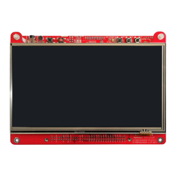
NuMaker-HMI-MA35D1-S1 7’’ TFT LCD Daughter Board This daughter board contains a 7’’ 4-wire resistive touch TFT LCD panel with pixel resolution of 1024x600. (TH0701024600NYR50L1 + AN-3748A) Figure 1-5 7’’ TFT LCD Daughter Board Nov. 2, 2022 Page 13 of 99 Rev 1.01... -
Page 14: Board Part Number And Information
NuMaker-HMI-MA35D1-S1 Board Part Number and Information The following table lists the part number of this evaluation board (EVB) based on the MA35D16A887C microprocessors, and the PCB names of three parts: NuMaker-SOM-MA35D16A81 SOM board, NuMaker-BASE-MA35D1B1 base board and 7” TFT-LCD daughter board. 7”... -
Page 15: Features
NuMaker-HMI-MA35D1-S1 FEATURES NuMaker-SOM-MA35D16A81 Features Target Chip: MA35D16A887C (BGA 312-Ball) MCP package with DDR3L (256 MB), which can run up to 800 MHz Power DC 5V input from the NuMaker-BASE-MA35D1B1 board through the SOM high speed – connector PMIC DA9062-3A: –... -
Page 16: 7'' Tft Lcd Daughter Board Features
NuMaker-HMI-MA35D1-S1 Two sets of UART transceivers and DB9 connectors Two sets of RS485 transceivers and header connectors Two sets of CAN FD transceivers and header connectors One 8-channel ADC header connector MEMS Mircrophone MEMS G-Sensor ... -
Page 17: Hardware Configuration
NuMaker-HMI-MA35D1-S1 HARDWARE CONFIGURATION NuMaker-SOM-MA35D16A81 Board 3.1.1 Front View Figure 3-1 shows the main components and connectors from the front side of NuMaker-SOM- MA35D16A81 board. Target Chip (U1): MA35D16A887C (BGA312) MCP package with DDR3L (256MB). PMIC Reset Key Battery Input (SW1) (J48) RGMII0... -
Page 18: Rtc Wake-Up Control
NuMaker-HMI-MA35D1-S1 3.1.4 RTC Wake-up Control Battery Input Connector (J48): DC 3V battery input connector to provide an additional optional power to keep the RTC power from the V pin of MA35D1 when the system is power off. RTC Wake-up Control Pins: The RTC_RPWR and RTC_nRWAKE pins of MA35D1 are the RTC wake-up control pins to control the related DC/DC power whether output voltages or not. -
Page 19: Emmc Nand Flash
1.35V on this NuMaker-SOM-MA35D16A81 board. Note * : No connection (NC) by default. For more detailed information about how to change the output voltage on VLDO4, please refer to the PMIC DA9062-3A Application Note on Nuvoton website. Table 3-2 PMIC (U2) Output Voltage U2.#... -
Page 20: Rgmii Gigabit Phy
NuMaker-HMI-MA35D1-S1 eMMC1_CLK eMMC1_DAT0 eMMC1_DAT1 eMMC1_DAT2 PJ10 eMMC1_DAT3 PJ11 Note *: No connection (NC) by default. Table 3-4 eMMC1 NAND Flash Device (U3) Pin Function 3.1.7 RGMII Gigabit PHY RGMII0 Gigabit PHY (U4): The RGMII0 MAC of MA35D1 needs an external Gigabit PHY (RTL8211FDI) to transform signal and pass these 4-pair differential signals to the Ethernet transformer on NuMaker-BASE-MA35D1B1 board through the SOM high speed connector P1. -
Page 21: High Speed Connectors
NuMaker-HMI-MA35D1-S1 RGMII1_MDIO RGMII1_TXCTL RGMII1_TXD0 RGMII1_TXD1 RGMII1_RXCLK RGMII1_RXCTL RGMII1_RXD0 RGMII1_RXD1 RGMII1_RXD2 RGMII1_RXD3 PF10 RGMII1_TXCLK PF11 RGMII1_TXD2 PF12 RGMII1_TXD3 PF13 Table 3-6 RGMII1 PHY (U5) Pin Funciton 3.1.8 High Speed Connectors SOM High Speed Connectors (P1 and P2): Two 120-pin high speed connectors (DF40C-120DP- 0.4V (51)) to connect with the NuMaker-BASE-MA35D1B1 board. - Page 22 NuMaker-HMI-MA35D1-S1 PJ14 PJ13 PN10 PJ12 PL15 PN11 PL14 PL13 PL12 PL11 PL10 PD14 PA14 PA13 PA12 PA11 PA10 E_MDIP0 E_MDIN0 E_MDIP1 E_MDIN1 E_MDIP2 PF14 E_MDIN2 E_LED0 E_LED1 E_MDIP3 E_LED2 E_MDIN3 F_LED0 F_LED1 Nov. 2, 2022 Page 22 of 99 Rev 1.01...
-
Page 23: Table 3-7 Som Connector 1 (P1) Pin Function
NuMaker-HMI-MA35D1-S1 F_MDIP0 F_LED2 F_MDIN0 EADC0_CH7 EADC0_CH3 F_MDIP1 EADC0_CH6 F_MDIN1 EADC0_CH2 EADC0_CH5 F_MDIP2 EADC0_CH1 F_MDIN2 EADC0_CH4 EADC0_CH0 F_MDIP3 F_MDIN3 HSUSB0_D+ HSUSB0_D- PE15 PE14 HSUSB1_D+ HSUSB0_ID HSUSB1_D- PF15 Table 3-7 SOM Connector 1 (P1) Pin Function Pin No. GPIO of MA35D1 or Function pin Pin No. - Page 24 NuMaker-HMI-MA35D1-S1 PI11 PH12 PI10 PH13 PH14 PH15 PB15 PB14 PG10 PB13 PB12 PB11 PB10 PM15 PM14 PM13 PM12 PG15 PG14 PG13 PG12 PD13 PG11 PD12 PD11 PD10 Nov. 2, 2022 Page 24 of 99 Rev 1.01...
-
Page 25: Table 3-8 Som Connector 2 (P2) Pin Function
NuMaker-HMI-MA35D1-S1 PK10 PK11 PM10 PM11 Table 3-8 SOM Connector 2 (P2) Pin Function Nov. 2, 2022 Page 25 of 99 Rev 1.01... -
Page 26: Numaker-Base-Ma35D1B1 Board
NuMaker-HMI-MA35D1-S1 NuMaker-BASE-MA35D1B1 Board 3.2.1 Front View Figure 3-3 shows the main components and connectors from the front side of NuMaker-BASE- MA35D1B1 board. CAN FD UART0 RS485 Connectors Connectors (CON17/CON18) Tamper (CON15/CON16) Pads VCOM Controller Connector Slide Switch (T3/T6) (J1) (U29, NUC123ZD4AN0) (SW1) VDD5V IN NUC123 ICE... -
Page 27: Power And Ground
NuMaker-HMI-MA35D1-S1 CAN FD RS485 Transceiver Transceiver Connector (U25/U26, TCAN337GD) (U23/U24, SN65HVD11DR) (CON9) Buzzer Pads (T23/T24) RS232 Audio Codec Transceiver (U18, NAU88C22) (U21, SN75C3232EDR) MEMS RGMII0 RJ45 G-Sensor Connector (U32, MPU6500) (U10) RGMII1 RJ45 SC0 SIM Card Connector (CON12) (U11) RS232 Speaker Pads Transceiver (T14/T15) - Page 28 NuMaker-HMI-MA35D1-S1 PN13 PK14 PK13 PK12 PJ15 PJ14 PJ13 PN10 PJ12 PL15 PN11 PL14 PL13 PL12 PL11 PL10 PD14 PA14 PA13 PA12 PA11 PA10 E_MDIP0 E_MDIN0 E_MDIP1 Nov. 2, 2022 Page 28 of 99 Rev 1.01...
-
Page 29: Table 3-9 Som Connector 1 (Con2) Pin Function
NuMaker-HMI-MA35D1-S1 E_MDIN1 E_MDIP2 PF14 E_MDIN2 E_LED0* E_LED1 E_MDIP3 E_LED2 E_MDIN3 F_LED0* F_LED1 F_MDIP0 F_LED2 F_MDIN0 EADC0_CH7 EADC0_CH3 F_MDIP1 EADC0_CH6 F_MDIN1 EADC0_CH2 EADC0_CH5 F_MDIP2 EADC0_CH1 F_MDIN2 EADC0_CH4 EADC0_CH0 F_MDIP3 F_MDIN3 HSUSB0_D+ HSUSB0_D- PE15 PE14 HSUSB1_D+ HSUSB0_ID HSUSB1_D- PF15 Note *: No connection (NC) by default. Table 3-9 SOM Connector 1 (CON2) Pin Function Pin No. - Page 30 NuMaker-HMI-MA35D1-S1 PI15 PC12 PI14 PC13 PI13 PC14 PI12 PC15 PI11 PH12 PI10 PH13 PH14 PH15 PB15 PB14 PG10 PB13 PB12 PB11 PB10 PM15 PM14 PM13 PM12 PG15 PG14 Nov. 2, 2022 Page 30 of 99 Rev 1.01...
-
Page 31: Qspi Flash
NuMaker-HMI-MA35D1-S1 PG13 PG12 PD13 PG11 PD12 PD11 PD10 PK10 PK11 PM10 PM11 Table 3-10 SOM Connector 2 (CON3) Pin Function 3.2.5 QSPI Flash QSPI0 Flash (U8): Winbond SPI NAND Flash (W25N04KWZEIR, 512 MB) for optional booting source, supporting dual / quad mode. Pin No. -
Page 32: Nand Flash
NuMaker-HMI-MA35D1-S1 QSPI0_SS0 QSPI0_MISO0 QSPI0_MOSI1 QSPI0_MOSI0 QSPI0_CLK QSPI0_MISO1 QSPI0_VDD* Note *: The power group of these GPIO PD0~PD5 belongs to the VDDIO5 power domain of MA35D1 series, the default voltage of VDDIO5 (power input VDD_QSPI0) is VDD1V8 (DC 1.8V) on the NuMaker-SOM-MA35D16A81 board. -
Page 33: Sd Card Slot
NuMaker-HMI-MA35D1-S1 3.2.7 SD Card Slot SD0 Standard-SD Card Slot (CON4): Support SD0 (SD2.0) for optional booting source. Pin No. Pin Name GPIO pin of MA35D1 Default Connected R# SD0_DTA3 SD0_CMD VDD3V3 SD0_CLK SD0_DAT0 SD0_DAT1 SD0_DTA2 SD0_nCD SD0_WP HOLD HOLD SD0_PWR_CTRL# PD14 R42*... -
Page 34: Table 3-14 Secure Boot Options
NuMaker-HMI-MA35D1-S1 SW4.1 / PG0* Secure Booting Enable High Disable Note *: The GPIO PG0 is internal weakly pull-down. Table 3-14 Secure Boot Options Options for booting source QSPI0 and SD/eMMC IO voltage selection: SW4.2 / PG1* Booting Source QSPI0 and SD/eMMC IO Voltage 3.3 V High 1.8 V... -
Page 35: Table 3-18 Ecc Options For Nand Flash Booting Source
NuMaker-HMI-MA35D1-S1 High BCH T12 High BCH T24 High High NO ECC Note *: These GPIO PG6 and PG7 are internal weakly pull-down. Table 3-18 ECC Options for NAND Flash Booting Source Options for booting from SD0/1 card or eMMC0/1 NAND Flash memory device: SW4.7 / PG6* Boot from SD/eMMC SD0/eMMC0 Boot... -
Page 36: Gigabit Ethernet Transformers And Rj45 Ports
NuMaker-HMI-MA35D1-S1 Note * : The GPIO PG4 is internal weakly pull-down. Note * : It does not support the USB Host booting source on this NuMaker-HMI-MA35D1-S1 board. Table 3-22 Options for USBD or USBH Booting Source SW7.6 / PG5* Boot from USBH* USBH Port 0 Booting High USBH Port 1 Booting... -
Page 37: Table 3-25 Ccap0 Connector (Con7) Pin Function
NuMaker-HMI-MA35D1-S1 CCAP0_SCLK R114 CCAP0_DATA0 R101 CCAP0_DATA1 R102 CCAP0_DATA2 R103 CCAP0_DATA3 R105 CCAP0_DATA4 R104 CCAP0_DATA5 R106 CCAP0_DATA6 R107 CCAP0_DATA7 R109 CCAP0_DATA8 PM10 R111 CCAP0_DATA9 PM11 R112 CCAP0_VSYNC R116 CCAP0_HSYNC PK11 R115 CCAP0_PWDN R118 CCAP0_nRST R117 CCAP0_I2C3_SCL PM15 TRACE_DATA3 / R302* CCAP0_I2C3_SDA PM14 TRACE_DATA2 / R301*... -
Page 38: External Bus Interface (Ebi) Connector
NuMaker-HMI-MA35D1-S1 CCAP1_DATA0 R119 CCAP1_DATA1 R120 CCAP1_DATA2 R121 CCAP1_DATA3 R122 CCAP1_DATA4 R123 CCAP1_DATA5 R124 CCAP1_DATA6 R125 CCAP1_DATA7 R128 CCAP1_VSYNC PN13 R132 CCAP1_HSYNC PN12 R131 CCAP1_PWDN PD15 R134 CCAP1_nRST PN14 R133 CCAP1_I2C4_SCL R100 CCAP1_I2C4_SDA VDD3V3 VDD3V3 Table 3-26 CCAP1 Connector (CON8) Pin Function 3.2.12 External Bus Interface (EBI) Connector ... - Page 39 NuMaker-HMI-MA35D1-S1 EBI_AD4 PG15 R193* JTAG_nTRST / R294 EBI_AD5 R195* TRACE_CLK / R303 EBI_AD6 EBI_AD7 R313* MPU6500_INT / R320 EBI_AD8 R314* I2S1_BCLK / R316 EBI_AD9 PD10 R315* I2S1_DI / R317 EBI_AD10 PD11 EBI_AD11 R196* UR11_nCTS / R245 EBI_AD12 R198* UR11_nRTS / R246 EBI_AD13 R200*...
-
Page 40: Eadc Connector
NuMaker-HMI-MA35D1-S1 EBI_ADR3 R180* UR12_TXD / R261 EBI_ADR4 EBI_ADR5 R181* UR14_nRTS / R266 EBI_ADR6 R182* UR14_RXD / R267 EBI_ADR7 R184* UR14_TXD / R271 EBI_ADR8 R199* UR16_nCTS / R249 EBI_ADR9 R201* UR16_nRTS / R250 EBI_ADR10 R204* UR16_RXD / R251 EBI_ADR11 R205* UR16_TXD / R252 EBI_ADR12 PJ12 R186*... -
Page 41: Uart
NuMaker-HMI-MA35D1-S1 EADC_CH4 EADC_CH4 EADC_CH6 EADC_CH6 EADC_CH1 EADC_CH1 EADC_CH3 EADC_CH3 EADC_CH5 EADC_CH5 EADC_CH7 EADC_CH7 AVSS_E* AVSS_E* Note *: AVSS_E is the EADC0 analog ground. Table 3-28 EADC0 Connector (J6) Pin Function 3.2.14 UART UART0 Port, Ground VSS and Tamper Pin Connector (J1): This connector includes the TXD/RXD pins of UART0, the ground VSS pins, and the tamper pins (TAMPER0, TAMPER1). -
Page 42: Rs485
NuMaker-HMI-MA35D1-S1 (SN75C3232EDR) and DB9 connector. Function GPIO pin of MA35D1 Default Connected R# Conflict Function / R# Name UR16_nCTS R249 EBI_ADR8 / R199* UR16_nRTS R250 EBI_ADR9 / R201* UR16_RXD R251 EBI_ADR10 / R204* UR16_TXD R252 EBI_ADR11 / R205* Note *: No connection (NC) by default. Table 3-31 UART16 (U22, CON14) Pin Function 3.2.15 RS485... -
Page 43: Swj, Swd And Etm
NuMaker-HMI-MA35D1-S1 Table 3-34 CAN1 (U25, CON17) Pin Function CAN Transceiver (U26) and Connector (CON18): The CAN3 transceiver (TCAN337GDR) and connector. Function GPIO pin of MA35D1 Default Connected R# Conflict Function / R# Name CAN3_RXD PL10 R276 EBI_nWRH / R206* CAN3_TXD PL11 R278... -
Page 44: Table 3-36 Swj Interface (Con19) Pin Function
NuMaker-HMI-MA35D1-S1 Note *: No connection (NC) by default. Table 3-36 SWJ Interface (CON19) Pin Function SWD Interface (J8): Arm SWD (Serial Wire Debug) interface for tracing or debugging code. Pin No. Pin Name GPIO pin of Default Conflict Function MA35D1 Connected R# / R#... -
Page 45: Usb Virtual Com (Vcom) Port
NUC123 ICE Interface (J9): The ICE interface of NUC123ZD4AN0 microcontroller (U29) for programming the internal Flash of NUC123 MCU. The internal Flash of NUC123 MCU had been programmed and acts as an USB VCOM device before this NuMaker-BASE-MA35D1B1 board be delivered by Nuvoton. Pin No. Pin Name Functions VCOM_3.3V... - Page 46 NuMaker-HMI-MA35D1-S1 Pin No. Pin Name GPIO pin of Default Conflict Function MA35D1 Connected R# / R# VDD3V3 VDD3V3 LCM_CS R151 LCM_BLEn R152 LCM_DEN R149 LCM_VSYSNC R153 LCM_HSYNC R147 LCM_CLK PG10 R148 LCM_DATA23 PH15 R177 LCM_DATA22 PH14 R176 LCM_DATA21 PH13 R175 LCM_DATA20 PH12 R174...
- Page 47 NuMaker-HMI-MA35D1-S1 LCM_DATA2 PI10 R156 LCM_DATA1 R155 LCM_DATA0 R154 LCM_PWM R150 LCM_RST PM12 R135 nRESET / R138* LCM_XP PB15 R144 LCM_I2C1_SCL / LCM_VSENSE PB11 R146* R145 LCM_XM PB14 R142 LCM_YM PB12 R137 LCM_YP PB13 R139 LCM_I2C5_SCL R143 EBI_ADR13 / PJ13 R188* LCM_I2C5_SDA R141 EBI_ADR12 /...
-
Page 48: Audio Codec
Headset Jack (CON11): A headset input jack that follows CTIA definition. Audio Codec Device (U18): Nuvoton NAU88C22YG is audio codec device that integrates microphone input, speaker output and headphone output for audio application on this NuMaker- BASE-MA35D1B1 board. -
Page 49: Sim Card Slot
NuMaker-HMI-MA35D1-S1 AUDIO_JKDET R234 EBI_ADR0 / R183* Note *: No connection (NC) by default. Table 3-43 Audio Codec (U18) Control Pin Function 3.2.22 SIM Card Slot SC0 SIM Card (CON12): SIM card slot for SC0. Function GPIO pin of MA35D1 Default Connected R# Conflict Function / R# Name... -
Page 50: Mems Digital Microphone
NuMaker-HMI-MA35D1-S1 Table 3-46 LEDs (LEDG4, LEDR1) Pin Function Buzzer Pads (T23 and T24): To connect a buzzer to output sound. 3.2.24 MEMS Digital Microphone MEMS Digital Mircrophone (U31): The MP34DT01-M is a digital MEMS microphone. Function GPIO pin of MA35D1 Default Connected R# Conflict Function / R# Name... -
Page 51: 7'' Tft Lcd Daughter Board
NuMaker-HMI-MA35D1-S1 7’’ TFT LCD Daughter Board 3.3.1 Front View Figure 3-5 shows the main components from the front view of 7’’ TFT LCD daughter board and an on- board 7’’ 4-wire resistive touch TFT LCD panel. 7”Touch LCD Panel Figure 3-5 Front View of 7’’ TFT LCD Daughter Board 3.3.2 Rear View Figure 3-6 shows the main components from the rear view of 7’’... -
Page 52: Connectors
NuMaker-HMI-MA35D1-S1 Connector (CON1) Touch Connector (CN4) LCD Module Connector (CN1) Figure 3-6 Rear View of 7’’ TFT LCD Daughter Board 3.3.3 Connectors LCD Module Connector (CON1): FPC (pitch-0.5mm x 50) connector of TFT LCD module. LCM Connector (CON2): To connect with the LCM connector (CON9) of the NuMaker-BASE- MA35D1B1 board. -
Page 53: Quick Start
4.1.1 Insert SD Card The first step is to insert the Standard SD card that had been programmed with an image file by Nuvoton to the SD0 Standard-SD card slot (CON4) on the NuMaker-BASE-MA35D1B1 board. Figure 4-1 SD0 Standard-SD Card Slot (CON4) 4.1.2... -
Page 54: Power On The Numaker-Base-Ma35D1B1 Board
NuMaker-HMI-MA35D1-S1 Options for booting source selection: SW4.4 / PG3* SW4.3 / PG2* Boot Source QSPI0 Flash Low (OFF) High (ON) SD/eMMC High NAND Flash High High Note *: These GPIO PG2 and PG3 are internal weakly pull-down. Table 4-1 SD/eMMC Booting Source Configuration on Power-on Setting ... -
Page 55: Vcom Port (Optional)
NuMaker-HMI-MA35D1-S1 4.1.4 VCOM Port (Optional) User can connect the USB micro-B connector (CON21) and plug-in to the PC host with an USB cable to display the messages on PC when the evaluation environment is booting or CPU is running in the Linux kernel. -
Page 56: Embedder Demos
TFT LCD screen and can try to operate each demonstration on the TFT LCD screen by finger touch. For more detailed information about these demonstrations, please visit and browse Nuvoton website and search the related description or documents on the website. Figure 4-5 Main Screen of Demonstration 4.2.1... -
Page 57: Accelerator
NuMaker-HMI-MA35D1-S1 Figure 4-7 ML People Counting Demonstration 4.2.3 2D Accelerator The MA35D1 series supports the 2D hardware acceleration engine, Figure 4-8 shows the QT demonstration result that the MA35D1 uses the 2D engine through DirectFB to show the mice Blit pictures on the TFT LCD screen. -
Page 58: Data Security
NuMaker-HMI-MA35D1-S1 Figure 4-9 VoIP Demonstration 4.2.5 Data Security This demonstration shows how to use a Secure Key (SW key) to restore the protected data, the Secure Key is encrypted by the key stored in OTP (One-Time Program) in the OP-TEE OS. Figure 4-10 shows the data flow and structure about this demonstration. -
Page 59: Figure 4-11 Keyword Spotting By Rtp M4 Demonstration
NuMaker-HMI-MA35D1-S1 Figure 4-11 Keyword Spotting by RTP M4 Demonstration Nov. 2, 2022 Page 59 of 99 Rev 1.01... -
Page 60: Supporting Resources
Arm Cortex-A35 MPUs product line for the MA35D1 series products from the “Products” menu on Nuvoton website homepage. Figure 5-1 Nuvoton Website Software For more details about MA35D1 series software, for example, BSP (Board Support Package), Yocto, website. -
Page 61: Figure 5-2 Ma35D1 Github Resources
NuMaker-HMI-MA35D1-S1 9. MA35D1 · Yocto · · Buildroot · · TF-A · · OP-TEE · · U-Boot · · Linux-5.4.y · · Linux-5.10.y · · Linux Applications · · RTP · · OpenWrt · · NuWritter · · Docker · ·... -
Page 62: Hardware Schematics
DF40C-120DP-0.4V(51) DF40C-120DP-0.4V(51) SCHEMATIC03 SCHEMATIC07 SCHEMATIC08 SCHEMATIC04 VDD1V35 VDD1V35 VDD3V3 VDD3V3 VDD2V5 VDD2V5 VDD1V8 VDD1V8 nuvoTon Technology Corp. SCHEMATIC08 SCHEMATIC04 Title NuMaker-SOM-MA35D16A81 (BGA312) H-3.4X6(NC) H-3.4X6(NC) H-3.4X6(NC) Size Document Number System Block Tuesday, July 19, 2022 Date: Sheet Figure 6-1 System Block Nov. -
Page 63: Pmic, Crystal And Power Filter Schematic
PMIC_I2C0_SDA TXC-9H T9 SMD 32.768KHz 30ppm XT1_IN XT1_OUT DA9062-3AAMC X32_IN X32_OUT 0.1u nuvoTon Technology Corp. XOUT VDD3V 100K(NC) 24MHz Title P i n 2 8 G P I O 2 - NuMaker-SOM-MA35D16A81 (BGA312) L : P i n 2 4 V B U C K 4 = 1 . 3 5 V ( d e f a u l t ) -
Page 64: Power Group 0, 2, 4 And 5 Schematic
PH13 PH13/UART14_nRTS/UART13_TXD/LCM_DATA21 PH14 PH14/UART14_RXD/LCM_DATA22 LCM/UART_3,4,5,6,7,8,9,10,11,12,13,14 PH15 PH15/UART14_TXD/LCM_DATA23 CAN_0,3/I2C_3/PWM_1/SPI_2/INT_1,2,3/CLKO VDD3V3 VDDIO4 MA35D16A887C nuvoTon Technology Corp. 0.1u Title NuMaker-SOM-MA35D16A81 (BGA312) Size Document Number VDDIO0/2/4/5 Date: Tuesday, July 19, 2022 Sheet Figure 6-3 Power Group 0, 2, 4 and 5 Schematic Nov. 2, 2022 Page 64 of 99 Rev 1.01... -
Page 65: Power Group 1 Schematic
PM13 PM13/EPWM1_CH5/UART10_nRTS/TRACE_DATA1/UART11_TXD/I2C2_SCL/EBI_AD9/ECAP1_IC0/TM8_EXT PM14 PM14/EPWM1_BRAKE0/UART10_RXD/TRACE_DATA2/CAN2_RXD/I2C3_SDA/EBI_AD10/ECAP1_IC1/TM10/INT1 PM15 PM15/EPWM1_BRAKE1/UART10_TXD/TRACE_DATA3/CAN2_TXD/I2C3_SCL/EBI_AD11/ECAP1_IC2/TM10_EXT/INT2 UART_0 PE14 PE14/UART0_TXD PE15 PE15/UART0_RXD VDD3V3 VDDIO1 nuvoTon Technology Corp. MA35D16A887C Title 0.1u NuMaker-SOM-MA35D16A81 (BGA312) Size Document Number VDDIO1 Date: Tuesday, July 19, 2022 Sheet Figure 6-4 Power Group 1 Schematic Nov. 2, 2022 Page 65 of 99 Rev 1.01... -
Page 66: Power Group 3 (Emmc1_Pj) Schematic
N.C. eMMC1_CLK N.C. RESET N.C. RST_n VCCQ C170 C171 C172 C173 nuvoTon Technology Corp. Title NuMaker-SOM-MA35D16A81 (BGA312) Size Document Number eMMC1 (VDDIO3) Date: Tuesday, July 19, 2022 Sheet Figure 6-5 Power Group 3 (eMMC1_PJ) Schematic Nov. 2, 2022 Page 66 of 99... -
Page 67: Power Group 6, 7, Adc And Usb Schematic
PB13/EPWM2_CH1/UART4_nRTS/UART3_TXD/I2C3_SCL/CAN2_TXD/I2S1_BCLK/ADC0_CH5(Y P)/EBI_ADR17/ECAP2_IC1 PB14 PB14/EPWM2_CH2/UART4_RXD/CAN1_RXD/I2C4_SDA/I2S1_DI/ADC0_CH6(XM)/EBI_ADR18/ECAP2_IC2 PB15 PB15/EPWM2_CH3/UART4_TXD/CAN1_TXD/I2C4_SCL/I2S1_DO/ADC0_CH7(XP)/EBI_ADR19 VDD3V3 AVDD_ADC0 ADC/PWM_2/UART_1,2,3,4/CAN_0,1,2/I2C_2,3,4/SPI_0/I2S_1/INT_1,2 AVSS C104 C105 MA35D16A887C nuvoTon Technology Corp. 0.1u Title NuMaker-SOM-MA35D16A81 (BGA312) AVSS Size Document Number VDDIO6/7/ADC/USB Date: Tuesday, July 19, 2022 Sheet Figure 6-6 Power Group 6, 7, ADC and USB Schematic Nov. -
Page 68: Power Group 8 (Rgmii0_Pe) Schematic
0.1u 0.1u E_LED0 E_LED1 0.1u E_LED1 E_LED2 E_LED2 nRESET nRESET VDD3V3 C121 0.1u E_AVDD3V3 VDD3V3 nuvoTon Technology Corp. VDD1V8 VDD1V8 Title NuMaker-SOM-MA35D16A81 (BGA312) 4.7K E_VDD3V3 Size Document Number 4.7K RGMII0_RTL8211F(D)I (VDDIO8) E_DVDDRG Date: Tuesday, July 19, 2022 Sheet Figure 6-7 Power Group 8 (RGMII0_PE) Schematic Nov. -
Page 69: Power Group 9 (Rgmii1_Pf) Schematic
F_MDIN3 0.1u 0.1u F_MDIN3 0.1u F_LED0 F_LED0 F_LED1 F_LED1 F_LED2 F_LED2 nRESET C137 0.1u F_AVDD3V3 nRESET nuvoTon Technology Corp. VDD3V3 VDD3V3 Title VDD1V8 NuMaker-SOM-MA35D16A81 (BGA312) VDD1V8 4.7K F_VDD3V3 Size Document Number 4.7K RGMII1_RTL8211F(D)I (VDDIO9) F_DVDDRG Date: Tuesday, July 19, 2022... -
Page 70: Ddr Phy Schematic
0.1u 0.1u DDR PHY C180 1K(1%) 240(1%) 240(1%) C0402 R0402 R0402 R0402 nuvoTon Technology Corp. Title NuMaker-SOM-MA35D16A81 (BGA312) Size Document Number DDR3L Date: Tuesday, July 19, 2022 Sheet Figure 6-9 DDR PHY Schematic Nov. 2, 2022 Page 70 of 99... -
Page 71: Pcb Placement
NuMaker-HMI-MA35D1-S1 6.1.10 PCB Placement Figure 6-10 and Figure 6-11 show the front and rear PCB component placement of the NuMaker-SOM- MA35D16A81 board. Figure 6-10 Front PCB Placement of NuMaker-SOM-MA35D16A81 Board Nov. 2, 2022 Page 71 of 99 Rev 1.01... -
Page 72: Figure 6-11 Rear Pcb Placement Of Numaker-Som-Ma35D16A81 Board
NuMaker-HMI-MA35D1-S1 Figure 6-11 Rear PCB Placement of NuMaker-SOM-MA35D16A81 Board Nov. 2, 2022 Page 72 of 99 Rev 1.01... -
Page 73: Numaker-Base-Ma35D1B1 Schematics
10uF 4.7uF 0.1uF FP6381AS5CTR C0603 4.7uF 10uF C0603 C0603 C0603 TSOT-25 200K C0603 C0603 R0603 nuvoTon Technology Corp. 1.8V 100K Title NuMaker_MA35D1_Base R0603 Size Document Number Custom V2.0 Power Date: Tuesday, March 01, 2022 Sheet Figure 6-12 Power Schematic Nov. 2, 2022 Page 73 of 99 Rev 1.01... -
Page 74: Som Connectors Schematic
UART0 & Tamper HSUSB0_D- PE15 PE14 HSUSB1_D+ PK11 HSUSB0_ID HSUSB1_D- PM10 PF15 PM11 nuvoTon Technology Corp. DF40C-120DS-0.4V (51) (Pitch 0.4mm, female) DF40C-120DS-0.4V (51) (Pitch 0.4mm, female) Title NuMaker_MA35D1_Base Size Document Number V2.0 SOM Connectors Date: Tuesday, April 26, 2022 Sheet Figure 6-13 SOM Connectors Schematic Nov. -
Page 75: Power-On Setting And Nand Flash Schematic
USBD booting NAND flash page 2KB USBH booting NAND flash page 4KB NAND flash page 8KB Booting from USBH USBH port 0 booting nuvoTon Technology Corp. Booting from NAND USBH port 1 booting Ignore BCH T12 Booting from USBH Title... -
Page 76: Sd0 Schematic
0.1u C0603 C0603 TSOP-6 R0603 NSP4201MR6T1G 0.01uF C0603 SD0 Power Ctrl Note: SD0_VDD3V3 always ON (uncontrollable) by default. nuvoTon Technology Corp. Title NuMaker_MA35D1_Base Size Document Number V2.0 Date: Tuesday, March 01, 2022 Sheet Figure 6-15 SD0 Schematic Nov. 2, 2022 Page 76 of 99 Rev 1.01... -
Page 77: Qspi0 Schematic
QSPI0_MOSI0 QSPI0_MOSI0 QSPI0_VDD Di/D0 QSPI0_SS0 W25N04KWZEIR (SPI NAND) QSPI0_MOSI1 QSPI0_MISO0 QSPI0_RST HEADER 4x1 (2.54mm, NC) HEADER 5x1 (2.54mm, NC) nuvoTon Technology Corp. Title NuMaker_MA35D1_Base Size Document Number V2.0 QSPI0 Date: Thursday, February 10, 2022 Sheet Figure 6-16 QSPI0 Schematic Nov. 2, 2022 Page 77 of 99 Rev 1.01... -
Page 78: Eadc0 Schematic
0.1u 0.1u C0603 C0603 C0603 C0603 C0603 C0603 C0603 C0603 AVSS_E AVSS_E EADC0 nuvoTon Technology Corp. Title NuMaker_MA35D1_Base Size Document Number EADC0 V2.0 Date: Tuesday, April 26, 2022 Sheet Figure 6-17 EADC0 Schematic Nov. 2, 2022 Page 78 of 99... -
Page 79: Rgmii0_Pe Schematic
0.01uF C0603 C0603 C0603 1000pF/2KV 100pF C1206 C0603 1000pF/2KV C1206 Reserved for EMI (optional) nuvoTon Technology Corp. Title NuMaker_MA35D1_Base Size Document Number V2.0 Ethernet 0 (PE) Date: Thursday, February 10, 2022 Sheet Figure 6-18 RGMII0_PE Schematic Nov. 2, 2022 Page 79 of 99... -
Page 80: Rgmii1_Pf Schematic
0.01uF C0603 C0603 C0603 1000pF/2KV 100pF C1206 C0603 1000pF/2KV C1206 Reserved for EMI (optional) nuvoTon Technology Corp. Title NuMaker_MA35D1_Base Size Document Number Ethernet 1 (PF) V2.0 Date: Thursday, February 10, 2022 Sheet Figure 6-19 RGMII1_PF Schematic Nov. 2, 2022 Page 80 of 99... -
Page 81: Hsusb 0/1 Schematic
TSOP-6 Base Emitter 4.7K VDD5V VBUS1_5V NSP4201MR6T1G R0603 VOUT 0.01uF VOUT VOUT HSUSBH_PWREN HSUSBH_OVC C0603 AP2511M8-13 nuvoTon Technology Corp. CB25 MSOP-8 0.1u 10uF C0603 Title C0603 C0603 R0603 NuMaker_MA35D1_Base HSUSB1 Host Size Document Number V2.0 HSUSB 0/1 Tuesday, March 01, 2022... -
Page 82: Ccap 0/1 Connector Schematic
CCAP1_I2C4_SCL CCAP1_I2C4_SDA R130 33 PN12 CCAP1_HSY NC VDD3V3 VDD3V3 R131 33 R0402 PN13 CCAP1_VSY NC R132 33 R0402 nuvoTon Technology Corp. PN14 R0402 CCAP1_nRST R133 33 PD15 CCAP1_PWDN R134 33 R0402 HEADER 12x2 (2.0mm, male) Title NuMaker_MA35D1_Base Size Document Number V2.0... -
Page 83: Lcm Connector Schematic
R167 33 R0402 TSOP-6 R0402 LCM_DATA14 LCM_I2C1_SDA LCM_I2C1_SCL R168 33 LCM_DATA15 R169 33 R0402 NSP4201MR6T1G PC12 LCM_DATA16 R170 33 R0402 nuvoTon Technology Corp. PC13 LCM_DATA17 R171 33 R0402 PC14 R0402 LCM_DATA18 R172 33 PC15 LCM_DATA19 R173 33 R0402 Title PH12 LCM_DATA20... -
Page 84: Ebi Connector Schematic
R201 R0603 PD13 EBI_nCS2 R203 EBI_ADR10 PD10 EBI_AD9 R204 R0603 R315 R0603 R0603 EBI_nWRH/L (CAN_3) EBI_ADR11 R205 R0603 nuvoTon Technology Corp. PL10 EBI_nWRH R206 EBI_MCLK (LCM_I2C1_SDA) R0603 Title NuMaker_MA35D1_Base PL11 EBI_nWRL R207 PB10 EBI_MCLK R208 R0603 Size Document Number R0603 V2.0... -
Page 85: Nau88C22 Audio Codec Schematic
R0603 10uF VSSA Earphone R0603 R230 VSSA VSSA C0603 R0603 PK15 I2S0_DO R231 R232 R0603 R0603 nuvoTon Technology Corp. VSSA AUDIO_JKEN# (EBI_nCS2) AUDIO_JKDET (EBI_ADR0) Title NuMaker_MA35D1_Base PD13 AUDIO_JKEN# AUDIO_JKDET Size Document Number R233 R234 CTIA R0603 R0603 NAU88C22 Audio Codec V2.0... -
Page 86: Sim Card Schematic
SC0_DAT R242 R0603 SIM Card PK14 SC0_RST R243 R0603 PK15 SC0_PWR R244 R0603 nuvoTon Technology Corp. Title NuMaker_MA35D1_Base Size Document Number V2.0 SIM Card Date: Thursday, February 10, 2022 Sheet Figure 6-25 SIM Card Schematic Nov. 2, 2022 Page 86 of 99... -
Page 87: Rs232 Schematic
UR16_nRTS R0603 C0603 T2in UR16_CT UR16_nCTS 0.01uF R2in UR16_TXD R252 C0603 R0603 SN75C3232EDR nuvoTon Technology Corp. Title NuMaker_MA35D1_Base Size Document Number V2.0 RS232 Date: Thursday, February 10, 2022 Sheet Figure 6-26 RS232 Schematic Nov. 2, 2022 Page 87 of 99... -
Page 88: Rs485 Schematic
R268 UR14_RXD R267 R0603 R0603 R0603 UR14_TXD R0603 RS485_B3_2 R271 R0603 R272 R0603 nuvoTon Technology Corp. Title NuMaker_MA35D1_Base Size Document Number RS485 V2.0 Date: Thursday, February 10, 2022 Sheet Figure 6-27 RS485 Schematic Nov. 2, 2022 Page 88 of 99... -
Page 89: Can Fd Schematic
R0603 CB44 TCAN337GDR 0.1u HD-351-02P PL11 CAN3_TXD R278 C0603 R0603 R0603 CAN3_H nuvoTon Technology Corp. Title NuMaker_MA35D1_Base Size Document Number CAN FD V2.0 Date: Thursday, February 10, 2022 Sheet Figure 6-28 CAN FD Schematic Nov. 2, 2022 Page 89 of 99... -
Page 90: Key Buttons, Leds And Buzzer Schematic
R0603 VDD3V3 KEY 2 KEY 3 R287 Key Buttons R0603 BUZZER R288 R0603 S8550 (PNP) Collector T23 BZ+ (NC) nuvoTon Technology Corp. S8550 (PNP) BUZZER T24 BZ- (NC) BZ OUT Title Base Emitter NuMaker_MA35D1_Base Buzzer Size Document Number V2.0 Key Buttons, LEDs and Buzzer... -
Page 91: Swj, Swd And Etm Connectors Schematic
TRACEDATA[2] PM14 TRACE_DATA2 TRACE_DATA3 R301 TRACEDATA[3] R0603 SMD 1.27mm 10x2 PM15 TRACE_DATA3 R302 FTHS_1.27_ES_10X2 R0603 nuvoTon Technology Corp. ETM Connector TRACE_CLK (EBI_AD5) Title NuMaker_MA35D1_Base TRACE_CLK Size Document Number R303 R0603 SWJ, SWD and ETM Connectors V2.0 Date: Monday, March 07, 2022... -
Page 92: Nuc123 Vcom Schematic
15pF N123_D- N123_USB5V R307 C0603 VCOM_D- R0603 N123_D+ VCOM_D+ R308 R0603 N101 C0603 TSOP-6 nuvoTon Technology Corp. USB MICRO_AB RECEP. NSP4201MR6T1G Title 0.01uF NuMaker_MA35D1_Base C0603 Size Document Number V2.0 NUC123 VCOM Date: Thursday, February 10, 2022 Sheet Figure 6-31 NUC123 VCOM Schematic Nov. -
Page 93: Mems Digital Microphone Schematic
C0603 DOUT I2S1_BCLK R0603 PD10 R317 I2S1_DI R0603 R0603 MP34DT01-M MEMS Digital MIC nuvoTon Technology Corp. Title NuMaker_MA35D1_Base Size Document Number V2.0 MEMS Digital MIC (MP34DT01-M) Date: Thursday, February 10, 2022 Sheet Figure 6-32 MEMS Digital Microphone Schematic Nov. 2, 2022 Page 93 of 99 Rev 1.01... -
Page 94: Mems G-Sensor Schematic
0.1u C0603 R323 VDD3V3 R0603 CB48 MPU6500_INT 0.1u 10uF C0603 C0603 MEMS G-Sensor nuvoTon Technology Corp. Title NuMaker_MA35D1_Base Size Document Number V2.0 MEMS G-Sensor (MPU6500) Date: Thursday, February 10, 2022 Sheet Figure 6-33 MEMS G-Sensor Schematic Nov. 2, 2022 Page 94 of 99... -
Page 95: Pcb Placement
NuMaker-HMI-MA35D1-S1 6.2.23 PCB Placement Figure 6-34 and Figure 6-35 show the front and rear PCB component placement of the NuMaker-BASE- MA35D1B1 board. Figure 6-34 Front PCB Placement of NuMaker-BASE-MA35D1B1 Board Nov. 2, 2022 Page 95 of 99 Rev 1.01... -
Page 96: Figure 6-35 Rear Pcb Placement Of Numaker-Base-Ma35D1B1 Board
NuMaker-HMI-MA35D1-S1 Figure 6-35 Rear PCB Placement of NuMaker-BASE-MA35D1B1 Board Nov. 2, 2022 Page 96 of 99 Rev 1.01... -
Page 97: 7'' Tft Lcd Daughter Board Schematic
4.7K CVSS CT13 3.3V 10uF 0.1uF AVDD 9.6V SCL0 SCL_C RST_C VCOM SDA0 INT_C SCL1 0/NC SCL_C nuvoTon Technology Corp. SDA1 SDA_C VC33 SDA_C 0/NC CVSS Title VLED 9.6V/160mA RESET RST_C TFT-LCD7_ST70IPS INT_C Size Document Number CON__1mmX6 Tuesday, February 15, 2022... -
Page 98: Revision History
NuMaker-HMI-MA35D1-S1 REVISION HISTORY Date Revision Description · 2022.07.27 1.00 Initial version. · Updated Figure 1-1, Figure 1-2, Figure 1-3, Figure 5-2, Figure 6-2, and Table 3-1. · 2022.11.02 1.01 Updated the options about USB booting source in section 3.2.9. · Removed section 4.1.5. - Page 99 NuMaker-HMI-MA35D1-S1 Important Notice Nuvoton Products are neither intended nor warranted for usage in systems or equipment, any malfunction or failure of which may cause loss of human life, bodily injury or severe property damage. Such applications are deemed, “Insecure Usage”.
Need help?
Do you have a question about the NuMicro NuMaker-HMI-MA35D1-S1 and is the answer not in the manual?
Questions and answers