Sign In
Upload
Manuals
Brands
Nuvoton Manuals
Motherboard
NuMicro NuMaker-HMI-MA35D1-S1
Nuvoton NuMicro NuMaker-HMI-MA35D1-S1 Manuals
Manuals and User Guides for Nuvoton NuMicro NuMaker-HMI-MA35D1-S1. We have
1
Nuvoton NuMicro NuMaker-HMI-MA35D1-S1 manual available for free PDF download: User Manual
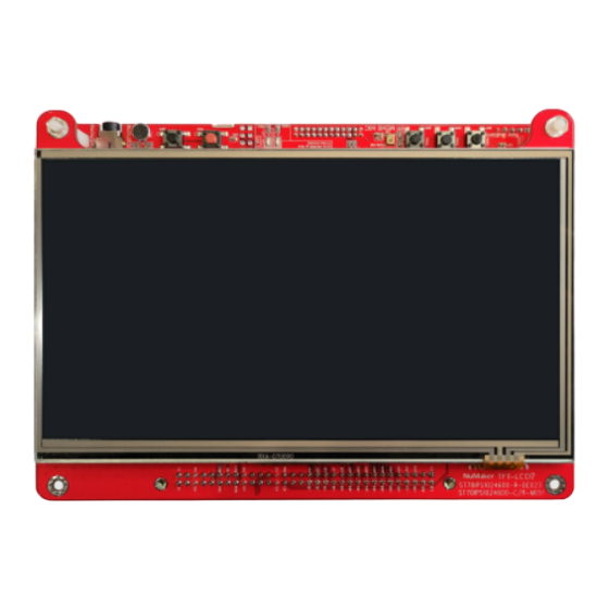
Nuvoton NuMicro NuMaker-HMI-MA35D1-S1 User Manual (99 pages)
Arm Cortex-A35-based Microprocessor
Brand:
Nuvoton
| Category:
Motherboard
| Size: 4 MB
Table of Contents
Table of Contents
2
Overview
9
Figure 1-1 Numaker-HMI-MA35D1-S1 Board from SOM Side
10
Figure 1-2 Numaker-HMI-MA35D1-S1 Board from TFT LCD Side
10
Numaker-SOM-MA35D16A81 Board
11
Figure 1-3 Numaker-SOM-MA35D16A81 Board
11
Numaker-BASE-MA35D1B1 Board
12
Figure 1-4 Numaker-BASE-MA35D1B1 Board
12
7'' TFT LCD Daughter Board
13
Figure 1-5 7'' TFT LCD Daughter Board
13
Board Part Number and Information
14
Table 1-1 Board Part Number and Information
14
Features
15
Numaker-SOM-MA35D16A81 Features
15
Numaker-BASE-MA35D1B1 Features
15
7'' TFT LCD Daughter Board Features
16
Hardware Configuration
17
Numaker-SOM-MA35D16A81 Board
17
Front View
17
Rear View
17
Power Input
17
Figure 3-1 Front View of Numaker-SOM-MA35D16A81
17
Figure 3-2 Rear View of Numaker-SOM-MA35D16A81
17
RTC Wake-Up Control
18
Pmic
18
Table 3-1 RTC Power Control Pins of MA35D1
18
Emmc NAND Flash
19
Table 3-2 PMIC (U2) Output Voltage
19
Table 3-3 PMIC (U2) Control Pins
19
RGMII Gigabit PHY
20
Table 3-4 Emmc1 NAND Flash Device (U3) Pin Function
20
Table 3-5 RGMII0 PHY (U4) Pin Funciton
20
High Speed Connectors
21
Table 3-6 RGMII1 PHY (U5) Pin Funciton
21
Table 3-7 SOM Connector 1 (P1) Pin Function
23
Table 3-8 SOM Connector 2 (P2) Pin Function
25
Numaker-BASE-MA35D1B1 Board
26
Front View
26
Rear View
26
Figure 3-3 Front View of Numaker-BASE-MA35D1B1
26
Power and Ground
27
High Speed Connectors
27
Figure 3-4 Rear View of Numaker-BASE-MA35D1B1
27
Table 3-9 SOM Connector 1 (CON2) Pin Function
29
QSPI Flash
31
Table 3-10 SOM Connector 2 (CON3) Pin Function
31
NAND Flash
32
Table 3-11 QSPI0 Flash (U8) Pin Function
32
Table 3-12 NAND Flash (U4) Pin Function
32
SD Card Slot
33
HS USB2.0 Connectors
33
Power-On Setting
33
Table 3-13 SD0 Standard-SD Card Slot (CON4) Pin Function
33
Table 3-14 Secure Boot Options
34
Table 3-15 Booting Source QSPI0 and Sd/Emmc IO Voltage Options
34
Table 3-16 Booting Source Options
34
Table 3-17 Page Size Options for NAND Flash Booting Source
34
Table 3-18 ECC Options for NAND Flash Booting Source
35
Table 3-19 Options for SD Card 0/1 or Emmc 0/1 NAND Flash Device Booting Source
35
Table 3-20 4/8-Bit Options for Emmc NAND Flash Device Booting Source
35
Table 3-21 1-Bit Options for QSPI0 NAND/NOR Flash Booting Source
35
Gigabit Ethernet Transformers and RJ45 Ports
36
CMOS Sensor Capture Connectors
36
Table 3-22 Options for USBD or USBH Booting Source
36
Table 3-23 USBH Port 0/1 Options for USBH Booting Source
36
Table 3-24 Over-Current High/Low-Active Detect Options for USBH Booting Source
36
Table 3-25 CCAP0 Connector (CON7) Pin Function
37
External Bus Interface (EBI) Connector
38
Table 3-26 CCAP1 Connector (CON8) Pin Function
38
EADC Connector
40
Table 3-27 EBI Connector (CON10) Pin Function
40
Uart
41
Table 3-28 EADC0 Connector (J6) Pin Function
41
Table 3-29 UART0 Port, Ground VSS and Tamper Pin Connector (J1) Pin Function
41
Table 3-30 UART11 (U21, CON13) Pin Function
41
Rs485
42
Can Fd
42
Table 3-31 UART16 (U22, CON14) Pin Function
42
Table 3-32 UART12 (U23, CON15) Pin Function
42
Table 3-33 UART14 (U24, CON16) Pin Function
42
SWJ, SWD and ETM
43
Table 3-34 CAN1 (U25, CON17) Pin Function
43
Table 3-35 CAN3 (U26, CON18) Pin Function
43
Table 3-36 SWJ Interface (CON19) Pin Function
44
Table 3-37 SWD Interface (J8) Pin Function
44
USB Virtual COM (VCOM) Port
45
Reset and RTC Wake-Up Key Buttons
45
TFT LCD Connector
45
Table 3-38 ETM Interface (CON20) Pin Function
45
Table 3-39 NUC123 ICE Interface (J9) Pin Function
45
Audio Codec
48
Table 3-40 LCM Connecor (CON9) Pin Function
48
Table 3-41 I2S0 (U18) Pin Function
48
Table 3-42 I2C2 (U18) Pin Function
48
SIM Card Slot
49
Key Buttons, Leds and Buzzer
49
Table 3-43 Audio Codec (U18) Control Pin Function
49
Table 3-44 SC0 SIM Card Connector (CON12) Pin Function
49
Table 3-45 Key Buttons (KEY_1, KEY_2, KEY_3) Pin Function
49
MEMS Digital Microphone
50
MEMS G-Sensor
50
Table 3-46 Leds (LEDG4, LEDR1) Pin Function
50
Table 3-47 MEMS Digital Mircrophone (U31) Pin Function
50
Table 3-48 MEMS G-Sensor (U32) Pin Function
50
7'' TFT LCD Daughter Board
51
Front View
51
Rear View
51
Figure 3-5 Front View of 7'' TFT LCD Daughter Board
51
Connectors
52
Figure 3-6 Rear View of 7'' TFT LCD Daughter Board
52
Quick Start
53
Hardware Setup and Power on
53
Insert SD Card
53
Configure Power-On Setting
53
Figure 4-1 SD0 Standard-SD Card Slot (CON4)
53
Figure 4-2 Power-On Setting DIP Switch (SW4)
53
Power on the Numaker-BASE-MA35D1B1 Board
54
Figure 4-3 Power Jack (CON1) and Slide Switch (SW1)
54
Table 4-1 Sd/Emmc Booting Source Configuration on Power-On Setting
54
Table 4-2 SD0 Booting Source Configuration on Power-On Setting
54
VCOM Port (Optional)
55
Figure 4-4 USB VCOM Port (CON21)
55
Embedder Demos
56
Video Playback
56
ML People Counting
56
Figure 4-5 Main Screen of Demonstration
56
Figure 4-6 H.264 Video Playback Demonstration
56
Accelerator
57
Voip Demonstration
57
Figure 4-7 ML People Counting Demonstration
57
Figure 4-8 2D Accelerator Demonstration
57
Data Security
58
Keyword Spotting by RTP M4
58
Figure 4-9 Voip Demonstration
58
Figure 4-10 Data Security Demonstration
58
Figure 4-11 Keyword Spotting by RTP M4 Demonstration
59
Supporting Resources
60
Documents
60
Software
60
Figure 5-1 Nuvoton Website
60
Figure 5-2 MA35D1 Github Resources
61
Hardware Schematics
62
Numaker-SOM-MA35D16A81 Schematics
62
System Block
62
Figure 6-1 System Block
62
PMIC, Crystal and Power Filter Schematic
63
Figure 6-2 PMIC, Crystal and Power Filter Schematic
63
Power Group 0, 2, 4 and 5 Schematic
64
Figure 6-3 Power Group 0, 2, 4 and 5 Schematic
64
Power Group 1 Schematic
65
Figure 6-4 Power Group 1 Schematic
65
Power Group 3 (Emmc1_Pj) Schematic
66
Figure 6-5 Power Group 3 (Emmc1_Pj) Schematic
66
Power Group 6, 7, ADC and USB Schematic
67
Figure 6-6 Power Group 6, 7, ADC and USB Schematic
67
Power Group 8 (RGMII0_PE) Schematic
68
Figure 6-7 Power Group 8 (RGMII0_PE) Schematic
68
Power Group 9 (RGMII1_PF) Schematic
69
Figure 6-8 Power Group 9 (RGMII1_PF) Schematic
69
DDR PHY Schematic
70
Figure 6-9 DDR PHY Schematic
70
PCB Placement
71
Figure 6-10 Front PCB Placement of Numaker-SOM-MA35D16A81 Board
71
Figure 6-11 Rear PCB Placement of Numaker-SOM-MA35D16A81 Board
72
Numaker-BASE-MA35D1B1 Schematics
73
Power Schematic
73
Figure 6-12 Power Schematic
73
SOM Connectors Schematic
74
Figure 6-13 SOM Connectors Schematic
74
Power-On Setting and NAND Flash Schematic
75
Figure 6-14 Power-On Setting and NAND Flash Schematic
75
SD0 Schematic
76
Figure 6-15 SD0 Schematic
76
QSPI0 Schematic
77
Figure 6-16 QSPI0 Schematic
77
EADC0 Schematic
78
Figure 6-17 EADC0 Schematic
78
RGMII0_PE Schematic
79
Figure 6-18 RGMII0_PE Schematic
79
RGMII1_PF Schematic
80
Figure 6-19 RGMII1_PF Schematic
80
HSUSB 0/1 Schematic
81
Figure 6-20 HSUSB 0/1 Schematic
81
CCAP 0/1 Connector Schematic
82
Figure 6-21 CCAP 0/1 Connectors Schematic
82
LCM Connector Schematic
83
Figure 6-22 LCM Connector Schematic
83
EBI Connector Schematic
84
Figure 6-23 EBI Connector Schematic
84
NAU88C22 Audio Codec Schematic
85
Figure 6-24 NAU88C22 Audio Codec Schematic
85
SIM Card Schematic
86
Figure 6-25 SIM Card Schematic
86
RS232 Schematic
87
Figure 6-26 RS232 Schematic
87
RS485 Schematic
88
Figure 6-27 RS485 Schematic
88
CAN FD Schematic
89
Figure 6-28 CAN FD Schematic
89
Key Buttons, Leds and Buzzer Schematic
90
Figure 6-29 Key Buttons, Leds and Buzzer Schematic
90
SWJ, SWD and ETM Connectors Schematic
91
Figure 6-30 SWJ, SWD and ETM Connectors Schematic
91
NUC123 VCOM Schematic
92
Figure 6-31 NUC123 VCOM Schematic
92
MEMS Digital Microphone Schematic
93
Figure 6-32 MEMS Digital Microphone Schematic
93
MEMS G-Sensor Schematic
94
Figure 6-33 MEMS G-Sensor Schematic
94
PCB Placement
95
Figure 6-34 Front PCB Placement of Numaker-BASE-MA35D1B1 Board
95
Figure 6-35 Rear PCB Placement of Numaker-BASE-MA35D1B1 Board
96
7'' TFT LCD Daughter Board Schematic
97
Figure 6-36 7'' TFT LCD Daughter Board Schematic
97
Revision History
98
Advertisement
Advertisement
Related Products
Nuvoton NuMicro NuMaker-HMI-N9H20
Nuvoton NuMaker-HMI-N9H26
Nuvoton NuMaker-HMI-M032K
Nuvoton NuMaker-HMI-N9H30
Nuvoton NuMaker-HMI-M467
Nuvoton NuMaker-HMI-MA35H0-A1
Nuvoton NuMaker-HMI-MA35H0-A2
Nuvoton NuMaker-HMI-N9H31-A1
Nuvoton NuMaker-HMI-N9H31-A2
Nuvoton NuMicro NuTiny-SDK-NANO100
Nuvoton Categories
Motherboard
Microcontrollers
Computer Hardware
Amplifier
Computer Accessories
More Nuvoton Manuals
Login
Sign In
OR
Sign in with Facebook
Sign in with Google
Upload manual
Upload from disk
Upload from URL