Table of Contents
Advertisement
Quick Links
NuMaker-HMI-N9H20
NuMicro
®
Family
Arm
®
ARM926EJ-S Based
NuMaker-HMI-N9H20
User Manual
Evaluation Board for NuMicro
®
N9H20 Series
The information described in this document is the exclusive intellectual property of
Nuvoton Technology Corporation and shall not be reproduced without permission from Nuvoton.
Nuvoton is providing this document only for reference purposes of NuMicro microcontroller and
microprocessor based system design. Nuvoton assumes no responsibility for errors or omissions.
All data and specifications are subject to change without notice.
For additional information or questions, please contact: Nuvoton Technology Corporation.
www.nuvoton.com
Mar. 15, 2022
Page 1 of 42
Rev 1.00
Advertisement
Table of Contents

Related Manuals for Nuvoton NuMicro NuMaker-HMI-N9H20


Summary of Contents for Nuvoton NuMicro NuMaker-HMI-N9H20
- Page 1 The information described in this document is the exclusive intellectual property of Nuvoton Technology Corporation and shall not be reproduced without permission from Nuvoton. Nuvoton is providing this document only for reference purposes of NuMicro microcontroller and microprocessor based system design. Nuvoton assumes no responsibility for errors or omissions.
-
Page 2: Table Of Contents
NuMaker-HMI-N9H20 Table of Contents 1 OVERVIEW ...................... 5 1.1 Features .......................... 5 1.1.1 NuMaker-N9H20 Main Board Features ................. 5 1.1.2 NuDesign-TFT-LCD4.3 Extension Board Features ............. 5 1.1.3 NuDesign-SPI2UART(B) Extension Board Features ..........5 1.2 Supporting Resources ....................6 2 NUMAKER-HMI-N9H20 BOARD HARDWARE CONFIGURATION ....7 2.1 NuMaker-HMI-N9H20 Jumper Description .............. - Page 3 NuMaker-HMI-N9H20 List of Figures Figure 2-1 NuMaker-N9H20 PCB Board (Front View) ..............7 Figure 2-2 NuMaker-N9H20 PCB Board (Rear View) ..............8 Figure 2-3 NuDesign-TFT-LCD4.3 PCB Board (Front View) ............8 Figure 2-4 NuDesign-TFT-LCD4.3 PCB Board (Rear View)............9 Figure 2-5 NuDesign-SPI2UART PCB Board(B) (Front View) ............9 Figure 2-6 NuMaker-N9H20 PCB Placement (Front View)............
- Page 4 NuMaker-HMI-N9H20 List of Tables Table 2-1 System Power Connectors .................... 10 Table 2-2 LED1 Power Indicator ....................10 Table 2-3 CON11 Pin Assignment ....................10 Table 2-4 CN2 (NuDesign-SPI2UART(B)) Pin Assignment ............11 Table 2-5 JP1 Connection Setting Assignment ................11 Table 2-6 JP4 Pin Assignment .......................
-
Page 5: Overview
NuMaker-HMI-N9H20 OVERVIEW The NuMaker-HMI-N9H20 is an evaluation board for GUI application development. The NuMaker-HMI- N9H20 consists of three parts: a NuMaker-N9H20 main board, a NuDesign-TFT-LCD4.3 extension board and a NuDesign-SPI2UART(B) extension board. The NuMaker-HMI-N9H20 is designed for project evaluation, prototype development and validation with HMI (Human Machine Interface) function. The NuMaker-HMI-N9H20 integrates touchscreen display, voice input/output, rich serial port service and I/O interface, providing multiple external storage methods. -
Page 6: Supporting Resources
NuMaker-HMI-N9H20 Supporting Resources For sample codes and introduction about NuMaker-N9H20, please refer to N9H20 BSP: https://www.nuvoton.com/products/gui-solution/gui-platform/numaker-hmi- n9h20/?group=Software&tab=2 Visit NuForum for further discussion about the NuMaker-HMI-N9H20: http://forum.nuvoton.com/viewforum.php?f=31&sid=7c6724e4048c11d6ce90f10ac837d52f Mar. 15, 2022 Page 6 of 42 Rev 1.00... -
Page 7: Numaker-Hmi-N9H20 Board Hardware Configuration
NuMaker-HMI-N9H20 NUMAKER-HMI-N9H20 BOARD HARDWARE CONFIGURATION Figure 2-1 shows the front view of NuMaker-N9H20 PCB board. SPI to UART Connector (CON2) LCD & CMOS Sensor Interface Connector (CON1) Microphones (M1, M2) Key Matrix (K1~K6) Figure 2-1 NuMaker-N9H20 PCB Board (Front View) Mar. -
Page 8: Figure 2-2 Numaker-N9H20 Pcb Board (Rear View)
NuMaker-HMI-N9H20 Figure 2-2 shows the rear view of NuMaker-N9H20 PCB board. 32.768KHz Crystal (X1) N9H20K51N (U1) RS-232 Transceivers (U9) 12MHz Crystal (X2) 5V DC Adaptor (CON3) UART Port (CON12) Power ON/OFF Switch (S3) USB2.0 Connector Headphone Jack (CON6) (CON9) JTAG Connector (CON11) SD0 Connector NAND Flash (U6) Audio Codec (U10) -
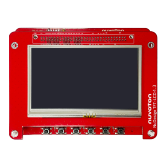
Page 9: Figure 2-4 Nudesign-Tft-Lcd4.3 Pcb Board (Rear View)
NuMaker-HMI-N9H20 Figure 2-7 shows the rear view of NuDesign-TFT-LCD4.3 PCB board. LCD Interface Connector (CON2) LCD Back Light Controller (U1) Figure 2-4 NuDesign-TFT-LCD4.3 PCB Board (Rear View) Figure 2-5 shows the front view of NuDesign-SPI2UART(B) PCB board. UART0 (CON1) UART1 (CON2) ICE Port (CN2) RS-232 Transceiver... -
Page 10: Numaker-Hmi-N9H20 Jumper Description
NuMaker-HMI-N9H20 NuMaker-HMI-N9H20 Jumper Description 2.1.1 Power Source CON3: 5V DC Adaptor input connector CON4 & CON5: External Battery connector S3: Power ON/OFF Switch Source Power port VD33 CON3 Connect to 5V DC Adaptor DC 3.3V VD33 & VD18 Power Enable PWREN of U2 &... -
Page 11: Usb Connector
NuMaker-HMI-N9H20 ICE_CLK ICE Interface Clock RSTn ICE Interface Reset, Active Low Power Ground Table 2-4 CN2 (NuDesign-SPI2UART(B)) Pin Assignment 2.1.4 USB Connector CON6: Mini USB Connector (USB 2.0 HS Device) 2.1.5 Extended Connectors CON1 and CON2: Show all extended pins in NuMaker-N9H20 2.1.6 Buttons and JUMPER ... -
Page 12: Pin Assignment For Extended Connectors
NuMaker-HMI-N9H20 Pin Assignment for Extended Connectors The NuMaker-N9H20 provides the N9H20K51N target chip functions on board and several extended connectors for user applications. Pin No Pin Name Pin Functions VD33 DC 3.3V Unused Power Ground Unused nRESET System Reset, Input, Active Low GPA0 SPI_INT GPA5/GPD4... -
Page 13: Table 2-10 Con12 (Numaker-N9H20) Pin Assignment
NuMaker-HMI-N9H20 Unused. Power Ground Unused. Unused. Unused. Unused. Table 2-10 CON12 (NuMaker-N9H20) Pin Assignment Pin No Pin Name Pin Function DC 3.3V VD33 DC 3.3V VD33 GPIO Port A bit 1. GPA1 GPIO Port A bit 6. GPA6 GPD11 GPIO Port D bit 11; LCD Data Enable GPD10 GPIO Port D bit 10;... - Page 14 NuMaker-HMI-N9H20 GPC8 GPIO Port C bit 8; LCD Data Bit 8 GPC7 GPIO Port C bit 7; LCD Data Bit 7 GPC6 GPIO Port C bit 6; LCD Data Bit 6 GPC5 GPIO Port C bit 5; LCD Data Bit 5 GPC4 GPIO Port C bit 4;...
-
Page 15: Table 2-11 Con1 (Numaker-N9H20) Pin Assignment
NuMaker-HMI-N9H20 Unused. Unused. GPB6 GPIO Port B bit 6; CMOS Sensor Bit 6 GPB5 GPIO Port B bit 5; CMOS Sensor Bit 5 GPB4 GPIO Port B bit 4; CMOS Sensor Bit 4 GPB3 GPIO Port B bit 3; CMOS Sensor Bit 3 GPB2 GPIO Port B bit 2;... - Page 16 NuMaker-HMI-N9H20 GPC11 GPIO Port C bit 11; LCD Data Bit 11. GPC10 GPIO Port C bit 10; LCD Data Bit 10. GPC9 GPIO Port C bit 9; LCD Data Bit 9. GPC8 GPIO Port C bit 8; LCD Data Bit 8. GPC7 GPIO Port C bit 7;...
-
Page 17: Table 2-12 Con2 (Nudesign-Tft-Lcd4.3) Pin Assignment
NuMaker-HMI-N9H20 Unused. Unused. Unused. Unused. Unused. Unused. Unused. Unused. Unused. Unused. Unused. Unused. Table 2-12 CON2 (NuDesign-TFT-LCD4.3) Pin Assignment Mar. 15, 2022 Page 17 of 42 Rev 1.00... -
Page 18: Numaker-Hmi-N9H20 Pcb Placement
NuMaker-HMI-N9H20 NuMaker-HMI-N9H20 PCB Placement Figure 2-6 shows the front view of NuMaker-N9H20 PCB placement. Figure 2-6 NuMaker-N9H20 PCB Placement (Front View) Mar. 15, 2022 Page 18 of 42 Rev 1.00... -
Page 19: Figure 2-7 Numaker-N9H20 Pcb Placement (Rear View)
NuMaker-HMI-N9H20 Figure 2-7 shows the rear view of NuMaker-N9H20 PCB placement. Figure 2-7 NuMaker-N9H20 PCB Placement (Rear View) Figure 2-8 shows the front view of NuDesign-TFT-LCD4.3 PCB placement. Figure 2-8 NuDesign-TFT-LCD4.3 PCB Placement (Front View) Mar. 15, 2022 Page 19 of 42 Rev 1.00... -
Page 20: Figure 2-9 Nudesign-Tft_Lcd4.3 Pcb Placement (Rear View)
NuMaker-HMI-N9H20 Figure 2-9 shows the rear view of NuDesign-TFT-LCD4.3 PCB placement. Figure 2-9 NuDesign-TFT_LCD4.3 PCB Placement (Rear View) Figure 2-10 shows the front view of NuDesign-SPI2UART(B) PCB placement. Figure 2-10 NuDesign-SPI2UART(B) PCB Placement (Front View) Mar. 15, 2022 Page 20 of 42 Rev 1.00... -
Page 21: Numaker-N9H20 N9H20K51N's Control Pin Functions
NuMaker-HMI-N9H20 NuMaker-N9H20 N9H20K51N’s Control Pin Functions Table 2-13 shows the NuMaker-N9H20 Function Control Pins Assignment. Pin No. GPIO AUDIO CMOS JTAG LCM-80 NAND SYSTEM UART GPB.0 SP_CLKO SD1_D1 UHL_DP1 GPB.14 LMVSYNC GPB.13 WDT_RSTn GPD.12 SPI0_CLK GPD.13 SPI0_CS0n GPD.14 SPI0_DI GPD.15 SPI0_DO GPE.4 SD0_D2... - Page 22 NuMaker-HMI-N9H20 GPC.8 SP_D0 LV_D8 LV_D8 GPC.7 LV_D7 LV_D7 GPC.6 LV_D6 LV_D6 GPC.5 LV_D5 LV_D5 GPC.4 LV_D4 LV_D4 GPC.3 LV_D3 LV_D3 GPC.2 LV_D2 LV_D2 GPC.1 LV_D1 LV_D1 GPC.0 LV_D0 LV_D0 GPD.11 LVDEN WDT_RSTn GPD.10 LVSYNC GPD.9 LHSYNC VDD18 GPB.15 LPCLK VDD33 SAR_VSS33 TP_YM TP_XM...
- Page 23 NuMaker-HMI-N9H20 GPD.3 HUR_CTS GPD.4 TRSTn SPI0_CS1n HUR_RTS UD_CDET VDD18 MVDD MVSS MVREF MVSSQ MVDDQ HP_VSS33 HP_VDD33 LHP_OUT RHP_OUT ADAC_VSS33 ADAC_VREF ADAC_VDD33 VDD33 VDD18 GPA.7 WDT_RSTn GPD.6 NBUSY1n SD2_D2 GPD.5 NBUSY0n SD2_D3 GPD.8 NWR0n SD2_CMD GPD.7 NREn SD2_CLK GPE.11 NCLE GPE.10 NALE GPE.9 NCS1n...
-
Page 24: Numaker-N9H20 Bom
NuMaker-HMI-N9H20 GPB.11 SP_D6 LV_D22 SPI1_DI GPB.10 SP_D5 LV_D21 SPI1_CS0n GPB.9 SP_D4 LV_D20 SPI1_CLK GPB.8 SP_D3 LV_D19 GPB.7 SP_D2 LV_D18 GPB.6 SP_D1 I2S_DI GPB.5 SP_D0 I2S_DO SD1_D2 GPB.4 PWR_DN I2S_LRCLK SD1_D3 GPB.3 SP_VSYNC I2S_BCLK SD1_CMD GPB.2 SP_HSYNC I2S_MCLK SD1_CLK GPB.1 SP_PCLK SD1_D0 UHL_DM1 Table 2-13 N9H20K51N Pin Functions Assignment... - Page 25 NuMaker-HMI-N9H20 CP16,C16,CP17,CP23, CP24,CP27,CP28,CP29,CP30, CP31 CP14,CP18,CP19,CP20,CP21, CAP_B CX7,CX6 RB161M IN4148 SOT23 LED1 Red LED LED0603 LX1,LX2 4.7uH L1,L2,L3,L4,L5,L6,L7,L8, L0603 L9,L10,L11,L12,L13, L15,L16,L17,L18,L19,L20, RN1,RN3,RN4,RN5 10KR RS1,RS2,RS4,RS6, R0603 RS3,RS5,R42,R44,R73,R74,R75 R1,R2,R3,R6,R15,R16,R49, R50,R9,R11,R13,R54 R37,R36 R0603 R52,R51 R0603 R43,R61,R67,R69,R70, R0603 R20,R25,R28,R31,R33 R0603 R5,R4 1K+/-1% R0603 R62,R65,R66,R68 R0603 R0603 R18,R21,R23,R24,R26,R27, R0603...
- Page 26 NuMaker-HMI-N9H20 R0603 R10,R12,R14,R19, 100K R0603 R53,R58,R4,R5 120K R0603 154K R0603 200K R0603 240K R0603 390K R0603 680K R0603 R0603 R0603 R63,R64,R71,R72 R0603 M2,M1 LF-6027-OPC-4 Q1,Q2 IS2301 SOT23 2N3906 SOT23 2N3904 SOT23 CON1 Header 32x2, 2.54mm, Male CON11 Header 10x2, w/ Box, Male Header 5x2, 90 degree, CON2 Female...
-
Page 27: Table 2-14 Numaker-N9H20 Bom
NuMaker-HMI-N9H20 XC6206P182MR SOT23 W55X16 SOIC-8 (208mil) Toshiba NAND 4-8G TSOP-48 SOIC-16 W25Q128BV (300mil) ICL-232E NOSIC-16L NAU8822 32-QFN SN74LVC1G79 SOT23-6 32.768KHz 12MHz S1(2/3), S12(1/2),S13(1/2),S15(2/3) R0402 S14(2/3) R0402 SW1,S2,S16,S18,S19,S20 SW2,S17 Short Pad J1,J2,J3 Pin Hole TP1,TP2,TP3,TP4 TEST Pad CON4 Header 3, 2.0mm, Male Table 2-14 NuMaker-N9H20 BOM Mar. -
Page 28: Nudesign-Tft-Lcd4.3 Bom
NuMaker-HMI-N9H20 NuDesign-TFT-LCD4.3 BOM Item Q'ty Reference Part Remark C0603 CB1,CB2,CB3,CB4,CB5 0.1u C0603 C0603 4.7u C0603 CT1,CT2,CT3,CT4,CT5 C0603 C1,C2,C3,C4,C6 22uH/1.1MHZ SMTDR32 RB521S-30 SOD-523 8P4R R0603 R0603 R1,R3,R4,R5 R0603 R0603 R2,R8,R9 R0603 100K R0603 220K R0603 ZT7418 SOT23-6 CON1 FPC-40/0.5mm, Upper Contacted. CON2 Header32x2, 2.54mm, Female. -
Page 29: Nudesign-Spi2Uart(B) Bom
NuMaker-HMI-N9H20 NuDesign-SPI2UART(B) BOM Item Q'ty Reference Part Remark CB1,CB2,CB3,CB4, 0.1u C0603 C1,C2,C3,C4 CP1,CP3,CP4 C0603 CAP_A L2,L1 L0603 R1,R2 R0603 Pad 1/2 R0402 (S1,S2,S3,S4,S5,S6,S7,S8,S9) MINI58FDE TSSOP_20L ICL-232E NOSIC-16L Header 5x2, 2.54mm, 90 degree, Male CN2,CN1 Header 5, 2.54mm, Male CON1,CON2 D-SUB-9, 90 degree, Female Table 2-16 NuDesign-SPI2UART(B) BOM Mar. -
Page 30: Numaker-Hmi-N9H20 Schematics
NuMaker-HMI-N9H20 NUMAKER-HMI-N9H20 SCHEMATICS NuMaker-N9H20 Function Blocks Circuit Figure 3-1 shows the NuMaker-N9H20 function blocks circuit. VD33 VD33 0.1u 0.1u CON1 3.3V 3.3V VD33 VD33 GPA1 GPA6 GPA1 GPA6 GPD11 GPD10 NAND VDEN VSYNC N9H20Kx GPD9 GPB15 GPA1 GPA6 HSYNC PCLK POWER GPB12 GPB11... -
Page 31: Numaker-N9H20 N9H20K51N Mpu Circuit
NuMaker-HMI-N9H20 NuMaker-N9H20 N9H20K51N MPU Circuit Figure 3-2 shows the NuMaker-N9H20 N9H20K51N MPU circuit. VDD33 nRST nRESET SN74LVC1G79 ESD7371 0.1u 0.1u 0.1u VD33 VDD33 ADAVREF VD33 VD18 CP10 CB10 0.1u 0.1u 0.1u 0.1u VD18 VDD18 ADAVSS RTC18V GPA[7:0] VD18 GPB[15:0] CP11 CP12 CB11 CB12... -
Page 32: Numaker-N9H20 Power Supply Circuit
NuMaker-HMI-N9H20 NuMaker-N9H20 Power Supply Circuit Figure 3-3 shows the NuMaker-N9H20 power supply circuit. CON3 DC5V SOT-23-GSD POWER 4.7uH RB161M 100K INDUCTOR IRON VD33 IS2301 0.1u 5VIN IS2301 PWREN CP18 LED1 CON4 Power CON5 ZT7104AS RX1 680K CB22 CP19 0.01u SOT23-5L 0.1u 2N3906 CP20... -
Page 33: Numaker-N9H20 Keys And Configuration Circuit
NuMaker-HMI-N9H20 NuMaker-N9H20 Keys and Configuration Circuit Figure 3-4 shows the NuMaker-N9H20 keys and configuration circuit. GPC5(RS2) GPC4(RS1) NAND Page Size None (by IBR) ND7(RS4) NAND Cycle SHORT Rec. Mode OPEN Nor. Mode VD33 ND5(RS6) ND4(RS5) MEMORY TYPE SDRAM LPDDR DDR2 VD33 10KR DOWN... -
Page 34: Numaker-N9H20 Usb2.0 And Sd0 Interface Circuit
NuMaker-HMI-N9H20 NuMaker-N9H20 USB2.0 and SD0 Interface Circuit Figure 3-5 shows the NuMaker-N9H20 USB2.0 and SD0 interface circuit. NSP4201 VD33 SD_CMD SD_D2 SD_D3 USB_CVSS VD33 NSP4201 VD33 200K SDVDD33 iSD_CLK SD_D0 USB_DET CON6 SD_D1 USBDM USBDM USBD USBDP 10KR 10KR NSP4201 USBDP 390K MICRO_USB... -
Page 35: Numaker-N9H20 Nand And Spi Flash Memory Circuit
NuMaker-HMI-N9H20 NuMaker-N9H20 NAND and SPI Flash Memory Circuit Figure 3-6 shows the NuMaker-N9H20 NAND and SPI flash memory circuit. CB25 CB26 0.1u 0.1u NVDD33 VD33 CP24 SPI0 W55X16 SPI0_CS NAND GPD12 SPI0_DI /HOLD SPI0_CLK GPD14 SPI0_DO GPD15 I/O0 SPI0_CLK I/O1 HOLD SPI0_DO I/O2... -
Page 36: Numaker-N9H20 Headphone Circuit
NuMaker-HMI-N9H20 NuMaker-N9H20 Headphone Circuit Figure 3-7 shows the NuMaker-N9H20 headphone circuit. VD33 HP DET(S14): 1/2: GPE0 2/3: GPD3 For HP detect 100K HP_DET HP_DET0 HP_DET1 0.01u ESD7371 CON9 DAC0 Headphone LOUT PJK-691 ROUT DAC1 PJK-634M L/RIN SEL (S12, S13) ESD7371 VD33 1/2: Fm N9H20Kx 2/3: Fm NAV8822... -
Page 37: Numaker-N9H20 Jtag And Uart Circuit
NuMaker-HMI-N9H20 NuMaker-N9H20 JTAG and UART Circuit Figure 3-8 shows the NuMaker-N9H20 JTAG and UART circuit. VD33 VD18 VD33 VD33 nTRST NSP4201 10KR VD18 VD33 IVD33 nRESET CON11 100K nTRST 0.1u RESET nRESET JTAG 0.1u nRESET RESET 2N3904 SW4-SMD NSP4201 HEADER10X2\BOX, 2.54mm 90 Degree ESD7371 UVD33 VD33... -
Page 38: Numaker-N9H20 Audio Codec Controller Circuit
NuMaker-HMI-N9H20 NuMaker-N9H20 Audio Codec Controller Circuit Figure 3-9 shows the NuMaker-N9H20 audio codec controller circuit. VREF AUXOUT2 CP26 VSSA AUO1 4.7u R63 10K MIC_L AUXOUT LMICN VSSA AUXout LMICP R64 10K AUO2 VSSP AUXOUT1 MICBIAS LMICP VSSP LMICP VSSSPK LMICN RSPKOUT LMICN GPIO2... -
Page 39: 3.10 Nudesign-Tft-Lcd4.3 Lcd Controller Circuit
NuMaker-HMI-N9H20 3.10 NuDesign-TFT-LCD4.3 LCD Controller Circuit Figure 3-10 shows the NuDesign-TFT-LCD4.3 LCD controller circuit. 10uF 10uF 0.1uF CON1 VD33 VD33 LED- FPC_40_0.5mm VD33 CON2 LED+ 3.3V 3.3V * UPPER CONTACT TYPE 10uF 0.1uF GPA1 BLEn 0.1uF VD33 LDEN LVSYNC LDEN LVsy nc LD16 LHSYNC... -
Page 40: 3.11 Nudesign-Spi2Uart(B) Controller Circuit
NuMaker-HMI-N9H20 3.11 NuDesign-SPI2UART(B) Controller Circuit Figure 3-11 shows the NuDesign-SPI2UART(B) Controller circuit. S1 SSn S6 TXD0 PWM2/IC6/T0/AIN4/P0.5 P0.4/AIN5/STADC/PWM3/IC3 TXD0_76 SPI_SSn_76 TXD0_76 TXD/AIN3/P0.6 P0.3/PWM5/IC5/AIN6 RXD0_76 RXD1_76 SPI_SSn TXD0 RXD/AIN2/P0.7 P0.2/ICPCK/OCDCK/RXD_1/SCL RSTn SPI_MISO_76 SPI_SSn_58 TXD0_58 RST/P2.0 P0.1/PWM4/IC4/MISO SPI_MOSI_76 INT0/OSCIN/AIN1/P3.0 P0.0/PWM3/IC3/MOSI/T1 SPI_CLK_76 INT1/AIN0/P1.7 P1.0/PWM2/IC2/SPCLK S2 CLK S7 TXD1... -
Page 41: Revision History
NuMaker-HMI-N9H20 REVISION HISTORY Date Revision Description 2022.03.15 1.00 Initial version. Mar. 15, 2022 Page 41 of 42 Rev 1.00... - Page 42 NuMaker-HMI-N9H20 Important Notice Nuvoton Products are neither intended nor warranted for usage in systems or equipment, any malfunction or failure of which may cause loss of human life, bodily injury or severe property damage. Such applications are deemed, “Insecure Usage”.
Need help?
Do you have a question about the NuMicro NuMaker-HMI-N9H20 and is the answer not in the manual?
Questions and answers