Table of Contents
Advertisement
Quick Links
Advertisement
Table of Contents

Related Manuals for Seitron BE COOL R1


Summary of Contents for Seitron BE COOL R1
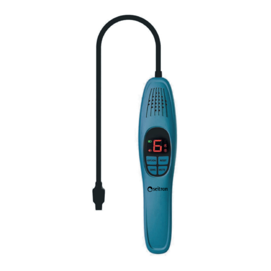
- Page 1 USE AND MAINTENANCE BE COOL R1 Refrigerant gas leak detector...
-
Page 3: Table Of Contents
INDICE IMPORTANT INFORMATION About this manual Safety Warnings. GENERAL FEATURES BATTERY INSERTION/REPLACEMENT MECHANICAL DESCRIPTION OPERATION Gas detection method Automatic and manual autozero setting Display of instrument sensitivity level Leak alarm / acoustic alarm silencing Error code summary table Automatic shutdown function Battery charge level display MAINTENANCE PRECAUTIONS... -
Page 4: Important Information
IMPORTANT INFORMATION About this manual ◊ This manual describes the operation, features, and maintenance of the leak detector. ◊ Read this manual before using the instrument. The operator must be familiar with the manual and follow its directions carefully. ◊ This operation and maintenance manual is subject to change as a result of technical improvements-the manufacturer assumes no responsibility for any content or printing errors. Respect your environment, think before you print the full manual. Safety Warnings. WARNING! Read the information carefully and set up appropriate measures to ensure safety so as to avoid any danger to people and property. -
Page 5: General Features
- Working humidity range: <80% RH (non-condensing). - Detected refrigerants: CFCs, HCFCs, HFCs, HCs and HFOs. Note: Applicable to all halogen refrigerants, including but not limited to: CFCs for example R12, R11, R500. R503; HCFCs for example R22, R123, R124, R502; HCFCs for example R134a, R404a, R410a, R407C, R32; HCs for example R600a, R290; HFOs for example R1234YF. - Sensor life: ≥1 year. - Autozero: automatic/manual. - Probe length: 420mm (16.5 in). - Battery life: 7 hours. - The instrument is accompanied by the calibration certificate. - Maintenance: Seitron advices to perform an yearly calibration to be performed at a Seitron assistance center. BATTERY INSERTION/REPLACEMENT Powered by 3 x 1.5V size AA batteries. Open the battery compartment on the back of the instrument and insert the supplied batteries correctly (observing correct polarity). RESPECT THE CORRECT POLARITY OF THE BATTERIES WARNING! Remove the protective tab inserted between the battery pole and the instrument contact before use. POLR020001SE 039609 060622... -
Page 6: Mechanical Description
MECHANICAL DESCRIPTION Display Flexible hose Sensor Keypad ON/OFF Power On / Off button. RESET Turn On / Off automatic autozero. MUTE Turns on/off the instrument acoustic signaling. ‘SENS’ button if pressed repeatedly cycles between the three instrument SENS sensitivities (High, Medium, Low). OPERATION •... -
Page 7: Gas Detection Method
• After the warm-up phase is over, the “0” symbol flashes on the screen, indicating that the instrument is ready for use; the buzzer icon is lit, and the instrument makes a sound every second. You can press the “MUTE” button to mute the buzzer. If the buzzer is already muted, press the “MUTE” button again to reactivate the buzzer. • By default, the instrument as soon as it is turned on will perform a sensor autozero, and the autozero icon (A) will be lit red. However, the autozero function can be disabled by holding down the autozero button “RESET” for at least three seconds; then the instrument will be in the manual autozero mode. The autozero in manual mode can be done by briefly pressing the “RESET” button; pressing this button for three seconds will re-enable the autozero mode. When the instrument is restarted, the autozero mode (A) will be restored. • After the warm-up phase, the sensitivity icon (S) will be red, indicating that the device is at its maximum sensitivity. • Place the nose of the probe where a leak is most likely to have occurred. If the instrument detects a leak, it will report a leak level on the display that is proportional to the amount of gas detected and will emit a sound; the greater the leak, the sharper the sound emitted by the instrument. It is recommended to move the instrument out of the area of the leak for at least 10 seconds before making a new detection pass. • When the work is finished, press the “OFF/ON” button 3 seconds to turn off the instrument. Note: Remove the insulation sheet from the battery compartment before first use. CAUTION: Pressing the “SENS” button cycles between three levels of instrument sensitivity (green=minimum, yellow=medium, red=maximum). Gas detection method The figure below exemplifies the method of leak detection: • Bend the flexible end of the instrument into the shape that best suits the case at hand; slowly move the probe closer to the leakage point. • If the instrument detects a leak it will signal this by showing a number from 1 to 7 on the display, where 1 is the minimum concentration level and 7 is the maximum. At the same time, the instrument will emit a sound to signal the presence of gas, the higher the frequency the higher the gas concentration. • Stand back and approach the area of suspected gas leak to confirm that there is indeed a leak at that location. • When the source of the leak has been found, it is necessary to report it and check the entire system until all leaks have been found and properly reported. Automatic and manual autozero setting So as to avoid the interference on detection caused by refrigerant in the environment, the detector allows the sensor to automatically self-zero. -
Page 8: Display Of Instrument Sensitivity Level
Display of instrument sensitivity level The display constantly shows the sensitivity level of the sensor; this can be set by pressing the ‘SENS’ button and cycling through the three available levels: High, Medium, Low: SENSITIVITY LEVEL INDICATOR SENSITIVITY LEVEL High Medium Orange Green Leak alarm / acoustic alarm silencing The detector is equipped with visual and audible signals. If a leak is detected, the instrument displays a number on a scale of 1 to 7 indicating the extent of the leak. The higher the amount of gas escaping from the leak, the closer the number on the screen will be to 7 and the sharper the audible signal will be. The user can decide whether to keep both signals (visual and audible) active or mute the audible alarm, keeping only the display indication. After the warm-up phase, the instrument operates normally and automatically activates the audible alarm; at this point it will be possible to press the “MUTE” button to activate/deactivate the audible alarm. Error code summary table 1 - In case an error occurs in the warm-up phase of the probe, only a service center can repair this fault. 2 - After solving the problem of the missing or failed probe, the instrument needs to redo the warm-up phase. 3 - When multiple faults occur simultaneously, the order of priority is: 1 -> 2 -> 3 ERROR CODE MEANING Missing power supply. Sensor not present or faulty. -
Page 9: Precautions
Sensor life: > 1 year Sensor warm-up time: 30 seconds Minimum detectable gas measurement: ≥3 gr/year. Replaceable sensor: Interchangeable by the user ≤3 seconds Response time: Measurement indication: Horizontal bars levels 0-7 Automatic shutdown function: User-settable Autozero: Automatic / Manual Display: In colored segments Acoustic indicator: Buzzer Operating temp: 0°C .. +50°C Storage temperature: -20°C .. +70°C Moisture limits: 20% .. 80% RH non-condensing Case size: 430x245x70 mm (LxAxP) Flexible stem length: 420mm WARRANTY In the interest of continuous development of its products, the manufacturer reserves the right to make changes in technical data and performance without prior notice. The consumer is guaranteed against product conformity defects according to the European Directive 2019/771 as well as the Seitron warranty policy document. The full text of the warranty is available from the seller upon request. POLR020001SE 039609 060622... - Page 12 Seitron S.p.A. a socio unico Via del Commercio, 9/11 - 36065 - MUSSOLENTE (VI) ITALY Tel. 0424.567842 - info@seitron.it - www.seitron.com...
Need help?
Do you have a question about the BE COOL R1 and is the answer not in the manual?
Questions and answers