Advertisement
Quick Links
RGY000MBP4
4 ZONES GAS DETECTION CENTRAL UNIT
230V~ power supply
Controls up to 4 zones
Manages CO, L.P.G. and Methane (CH
Wide parameters configuration freedom
Last alarm conditions data retention
LCD backlight 2 x 16 characters display
9 modules DIN rail mount
Compliant with EN60079-29-1 performance standard
─────────────────────────────────────────────────
[a] OPERATION, INSTALLATION AND MAINTENANCE
─────────────────────────────────────────────────
Operation
This is a microcontroller based device capable of monitoring the
gas concentration in up to 4 different zones: for each of these a
4 .. 20 mA transmitter can be wired for measurement and
detection of either L.P.G., Methane or Carbon Monoxide (CO).
After power-up the display shows the following information:
┌─zone 1─┐┌─zone 2─┐
│╔════════════════╗│
└║FIRMWARE:
┌║VERSION
│╚════════════════╝│
└─zone 3─┘└─zone 4─┘
where ' nnnnnn ' is the firmware version installed in the device.
This information will remain visible for about 2 seconds. After this
time the main information will be displayed (example):
┌─zone 1─┐┌─zone 2─┐
│╔════════════════╗│
└║G:
0%_
┌║G: 13%P
│╚════════════════╝│
└─zone 3─┘└─zone 4─┘
Each zone provides the following information:
The first letter from left explains the transmitter type wired to the
central unit.
The transmitters which can be wired to the central unit can be
different for each zone; the detectable gases are the following:
- L.P.G.:
- Methane (CH
):
4
- Carbon Monoxide:
Values displayed on the right, in % L.E.L. (in case L.P.G. or
Methane transmitters are connected) or ppm (in case of Carbon
Monoxide) are the actual gas concentration values measured by
the transmitters. The last letter shown on the display for each zone
indicates the actual state of the relevant transmitter as explained
in the following:
'_': Active state (measuring, normal operation).
'G': Fault on the 'G'as transmitter (Iout=2 mA).
'F': 'F'ault over the current loop (either short or open circuit
between any of the sensor wires: Iout=0 mA ).
'P': 'P'realarm state.
'A': 'A'larm state. When 'OVR' is shown in place of the
concentration value, this means that the upper limit of the
measuring range has been exceeded. The 'OVR' state
corresponds to an input current value above 20mA.
Prealarm and Alarm functions
The central unit can manage separately the pre-alarm and alarm
conditions through two distinct, Normally Open, output relays.
In case the prealarm threshold is reached, the central unit enables
the relevant relay, which, in turn, closes its output contacts.
In case the alarm threshold state is reached the unit will also
enable the alarm relay thus closing the relevant output contact. At
the same time the central unit has stored the pre-alarm state first
and the alarm state later: the date and hour when the last has
) transmitters
4
║┘
nnnnnn║┐
C: 50p_║┘
M: 50%A║┐
display shows letter 'G'
display shows letter 'M'
display shows letter 'C'.
SEITRON S.p.A. a socio unico
Via del Commercio, 9/11
36065 MUSSOLENTE (VI) - ITALY
Tel.: +39.0424.567842
Fax.: +39.0424.567849
http://www.seitron.com
e-mail: info@seitron.it
happened will be retained in the central unit memory.
In case the gas concentration returns below the pre-alarm
threshold, the relevant relay will return to its normal operation
state or not, according to how the prealarm relay operating mode
was set in the configuration.
Note: For compliance with the current performance standards the
Alarm relay has always a latched operation and this mode cannot
be modified by the user. Whenever either an Alarm situation ('A')
or an Overrange ('OVR') situation is reached, this relay is kept
energised together with the internal buzzer and the red led until
the user intentionally presses for 3 seconds the ' reset ' key.
Auxiliary relay
The central unit features one additional relay with changeover
contacts (SPDT) which can be activated according to events and
operating modes set by the installer through the relevant menu.
Display of the last alarm state
The central unit can retain the date and hour of the last alarm
event happened in each zone.
This information can be read by the user at any time by pressing
for 3 seconds the ' reset ' key when in main display screen, then
pressing '<' or '>' keys to cycle through the zones.
Electrical Wirings
The central unit is normally powered with 230V~ mains voltage.
At terminals 6 and 7 the user can wire a battery backup system
whose purpose is to grant full functionality to the central unit even
in case of power failure (see section [m] for details).
Normally Closed (NC) output of the auxiliary relay is available at
terminals 15 and 16, while the Normally Open (NO) one is
available at terminals 16 and 17.
This output can be used either for driving 'general purpose' loads
as a siren or an flashing light or, with proper configuration of the
relevant parameters, to drive a gas shut-off electrovalve.
Moreover this central unit features two single pole relay contacts
for each zone, one for prealarm and one for alarm.
The number of transmitters which can be wired to the central unit
is 4, each compliant with the 4..20 mA current loop system.
In order to make electrical wirings please refer to the suggested
wiring diagrams. Please also note that all the relay outputs of the
central unit do not feed power to the loads.
In other words all outputs are 'voltage free', giving the user more
freedom to use loads with several operating voltages.
WARNING
This Central Unit is NOT approved for installation in ATEX
classified zones.
All wirings with remote sensors must be made using wires
with 1,5 mm² minimum cross section and no longer than
25 m. Do not use same duct for signal wires and mains.
In case of installation where strong EMC disturbances are
present, it is highly suggested the use of shielded cables.
The shield must be connected to the 'Gnd' terminal of the
relevant zone on the Central Unit side only.
The appliance must be wired to the electric mains through a
switch capable of disconnecting all poles in compliance
with the current safety standards and with a contact
separation of at least 3 mm in all poles.
Installation and electrical wirings of this appliance must be
made by qualified technicians and in compliance with the
Advertisement

Subscribe to Our Youtube Channel
Related Manuals for Seitron RGY000MBP4


Summary of Contents for Seitron RGY000MBP4
- Page 1 RGY000MBP4 4 ZONES GAS DETECTION CENTRAL UNIT 230V~ power supply SEITRON S.p.A. a socio unico Controls up to 4 zones Via del Commercio, 9/11 Manages CO, L.P.G. and Methane (CH ) transmitters 36065 MUSSOLENTE (VI) - ITALY Wide parameters configuration freedom ...
- Page 2 enter password current technical and safety standards. Before wiring the appliance be sure to turn the mains power press 'enter' off. It is up to the installer (whose responsibility is to set-up a ┌────────────────┐ detection system compliance with existing...
- Page 3 ╔════════════════╗ values between 4 and 20mA into the correct value from 0% (or ║Zone1 management║ 0ppm) to the full scale. ║rst <> ent║ ╚════════════════╝ ╔════════════════╗ ║Zone1 management║ ║rst <> ent║ press 'enter', then '>' 5 times ╚════════════════╝ ┌────────────────┐...
- Page 4 ┌────────────────┐ │Aux rl mode: OPN│ Pressing '+' or '-' cycles press 'enter' │rst <> ent│ between 'OPN' and 'LCK' to store data └────────────────┘ ┌──────────────────────────────────────────────── LCK (locked): when the auxiliary relay is energized it remains │Change password energized even in case the triggering event is removed, i.e. the └────────────────────────────────────────────────...
-
Page 5: [K] Troubleshooting
┌─zone 1─┐┌─zone 2─┐ Contacts rating: Message displayed: │╔════════════════╗│ zone relays: 8 x 2A@230V~ cosφ=1 └║M: ║┘ auxiliary relay: 1 x 5A@250V~ cosφ=1 The red led flashes in correspondence with the symbol ' ' and Prealarm threshold range: Methane and L.P.G. 1%..100% LEL the buzzer sends an intermittent tone. - Page 6 The above mentioned CE Type Certificate has been issued for a This chart is valid for the use of a 4..20mA transmitter which system composed of this Central Unit (RGY000MBP4) and delivers 20mA in correspondence of 100% L.E.L.. Setting of the 4..20mA remote Gas Sensors (SGYME0V4XD).
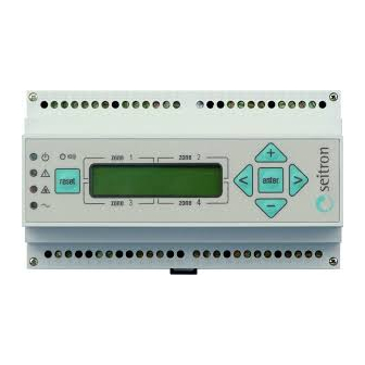
- Page 7 zone 1 zone 2 reset enter zone 3 zone 4 Fig. 5. Front panel - Keyboard explanation 9. Fault indicator. This indicator shows the presence of a fault in 1. Buzzer. Inside the central unit a buzzer is mounted which is a remote sensor or in the wiring to the central unit.
- Page 8 Aux RL Fig. 7. Wiring example with 230Vac NC electrovalve. A1..A4: Acoustic sirens (230Vac). These are activated when the alarm relay in each single zone is activated. Central unit. Type RGY 000 MBP 4. AuxRL: Auxiliary relay Battery backup system. This device must be capable Pr1..Pr4: Pre-alarm relays.
Need help?
Do you have a question about the RGY000MBP4 and is the answer not in the manual?
Questions and answers