Table of Contents
Advertisement
Quick Links
Advertisement
Table of Contents

Related Manuals for Seitron Multigas Be Safe MG


Summary of Contents for Seitron Multigas Be Safe MG
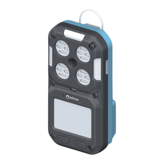
- Page 1 USE AND MAINTENANCE MG ---- Portable Multi-Gas Detector...
-
Page 3: Table Of Contents
INDICE IMPORTANT INFORMATION Information about this manual Safety warnings SAFETY Precautionary Safety Measures to Adopt TECHNICAL FEATURES Dimensions MEASUREMENT RANGES AND SENSOR ACCURACY SENSOR POSITION PRODUCT DESCRIPTION Product code table General features Available software 6.4 Calibration Certificate MECHANICAL DESCRIPTION 6.6 Definition of Multifunction Buttons 6.7 LED Definition Display icons and values setup... - Page 4 11.6.4 TWA Alarm Setup 11.7 Combustible 11.8 Data logging 11.9 Language 11.10 Clock 11.11 Device Info 11.12 Service 11.13 Reset Password 11.14 Operator 11.15 Diagnostics 11.16 Debug Service 12.0 MAINTENANCE 12.1 Routine maintenance 12.2 Cleaning 12.3 Scheduled maintenance 12.4 Replacing gas sensors 12.5 Replacing gas sensor filters 12.6 Instrument expandability...
-
Page 5: Important Information
IMPORTANT INFORMATION Information about this manual ◊ This manual describes the operation, features, and maintenance of the device. ◊ This manual must be read and followed carefully when using the product. In particular, safety instructions and information on the use and operation of the product must be read and followed carefully. Additionally, to ensure safe use, national regulations in force must be respected. Respect the environment, think before printing the full manual. Safety warnings WARNING! Carefully read the information and take adequate measures to ensure safety in order to avoid any danger to people and property. -
Page 6: Safety
Precautionary Safety Measures to Adopt Bump Test The frequency of the bump test is often regulated by national or company standards; however, as a general rule, performing a bump test before each use is the best safety practice and is therefore recommended by Seitron. The Canadian Standards Association (CSA) requires the bump test procedure for the LEL sensor to be performed before daily use, using calibration gas concentrations between 25% and 50% LEL. The instrument must be recalibrated if, during a bump test, the reading does not fall between 100% and 120% of the expected value for the gas. - Page 7 0.5% due to the displacement of oxygen by water vapor in the air. The oxygen sensor is equipped with a special filter that reduces the effects of humidity variations on oxygen readings. Its effect is not immediate but gradually influences oxygen readings over several hours. Temperature Variations The device has a built-in temperature compensation function. However, if the temperature changes rapidly, the sensor reading may vary. To minimize the effect, zero the device at the working temperature. If the device is used near its upper or lower operating temperature limit, Seitron recommends performing auto-zeroing or turning the device off and on in that environment. Special Conditions for Safe Use • In the event of an overrange condition for the flammable gas sensor, the device will enter Alarm Lock status, which must be reset in a fresh air environment. To reset this alarm, turn the device off and back on after moving to fresh air. Keep the device in fresh air until the LEL or CH4 readings have stabilized, then follow the instructions for Fresh Air Setup and Zero Calibration contained in this manual.
- Page 8 • The device is equipped with an anti-static coating on the LCD display to minimize the risk of ignition due to electrostatic discharge. Periodic inspection of this coating is necessary to ensure it is free from degradation, delamination, abrasions, or other surface deformations. • Care should be taken to avoid exposure to excessive heat, aggressive chemicals or solvents, sharp edges, and abrasive surfaces. Clean the exterior with a soft, damp cloth. • The products may contain materials whose transportation is regulated under national and international dangerous goods regulations. Return the product in accordance with the appropriate dangerous goods regulations. Contact the goods carrier for further instructions.
-
Page 9: Technical Features
TECHNICAL FEATURES Power Supply: Rechargeable internal Li-Ion battery 3.7 Vdc 2200 mA/h Communication Port: 4 gold-plated brass contacts Battery Charging Temperature: 10 °C to 30 °C Charging Time: <10 hours Charging Indicator: Red/green LED Fully Charged Indicator: Green LED + battery symbol on display Alarms: Audible Alarm: 90 dB @ 30 cm Vibration Alarm: Vibrating motor Visual Indicator: Steady green LED (Ok status) Visual Alarm: 3 flashing red LEDs Display: LCD display Device Runtime: Up to 18 hours Ingress Protection: IP67 Self-Diagnosis: Full function and internal sensor check with error reporting Autozero: Automatic zero calibration cycle at startup (5 seconds - time not adjustable) Internal Data Memory: 130,000 events automatically logged at 10-second intervals Data Logging 64,320 logs (data saved every 10 seconds) Operating Conditions Usage: Indoor and outdoor use Temperature: -20 °C to +55 °C... -
Page 10: Measurement Ranges And Sensor Accuracy
MEASUREMENT RANGES AND SENSOR ACCURACY MEASUREMENT RESPONSE TIME T90 POSITION MEASUREMENT SENSOR TYPE RESOLUTION ACCURACY RANGE Electrochemical Lead 0,1% Vol ±0,2% Vol <10 sec 0-25% Vol. free 0-1000 ppm Electrochemical 1ppm ±5 ppm <15 sec S2 - S3 - S4 0 .. 250 ppm Electrochemical 1ppm ±5 ppm <30 sec S2 - S3 - S4 0 .. -
Page 11: Product Description
S SO2 sensor S4 position Y H2 sensor K Cl2 sensor D CO + H2S sensor (dual) X Not sensor installed ---- Non ATEX related characters SE Branding Seitron General features The personal monitor is equipped with: • Electronic circuit which can host up to 4 sensors. • LEDs, vibrating motor, and buzzer for alarm notifications. •... -
Page 12: Mechanical Description
MECHANICAL DESCRIPTION Display Multifunction Button Multifunction Button Red LED: Alarm status indication Red LED: Alarm status indication Green LED: Normal operation indication ed LED: Alarm status indication Red LED: Battery charging in progress Green LED: Battery charging completed (visible only if the battery is charged with the instrument turned off) Buzzer Sensor Openings... -
Page 13: Definition Of Multifunction Buttons
Definition of Multifunction Buttons The device is equipped with two operating buttons. Each button activates interactive functions indicated on the display directly above the button itself. Below is the specific functionality of each button: Button Functions - Power On: Long press turns the device on. - Power Off: In the measurement screen, the interactive function “OFF” appears; a long press turns off the instrument. -
Page 14: Display Icons And Values Setup
Display icons and values setup Reference Description This part of the display shows several symbols: Battery Charge Status (for further details see section 7.2.1 Battery maintenance. The icon appears at startup if: At least one sensor has reached the end of its life (EOL). At least one sensor's calibration is expired and/or the last calibration failed. During operation, the icon appears if a bump test fails; it remains until the instrument is turned off. This symbol appears when the device is connected to the docking station, which is connected to the PC via USB cable, and the Be Safe MG Manager software is active. If the software is not active, the symbol briefly appears on the display. -
Page 15: Backlighting
Backlighting The display backlighting is always on. 6.10 Vibration Alarm The device is equipped with a vibration alarm. 6.11 Acoustic Alarm The acoustic alarm provides an audible warning. 6.12 Visual Alarm The visual alarm consists of flashing LEDs on the device. 6.13 Toxic Gas Monitoring The device monitors the concentration of toxic gases in the ambient air. During normal operation, it displays the concentration of gases in parts per million (ppm) or mg/m³ on the measurement page. -
Page 16: Flammable Gas Monitoring
6.15 Flammable Gas Monitoring The device is capable of monitoring ambient air concentrations of methane and other flammable gases, which can be selected from the SETUP->Fuel menu. The instrument displays the concentration of flammable gas in %Vol on the measurement page until another page is selected or the device is turned off. WARNING! If an alarm sounds during normal operation of the device, immediately leave the area. Remaining in the area under such circumstances exposes you to the risk of serious or fatal injuries. -
Page 17: Commissioning
It is recommended to provide both pieces of information for any technical assistance requests, spare parts, or technical and application clarifications. Seitron maintains a record of the historical data for each instrument at its headquarters. Before first use, it is recommended to perform a full battery charge cycle. Battery Charging and Indications The instrument is equipped with a rechargeable Li-Ion battery. - Page 18 Recharging batteries To charge the instrument's battery, use only the AMDS01 charging station, provided with the instrument. The charger can fully charge a completely discharged battery pack in less than six hours under normal conditions, at temperatures between 10°C and 30°C. WARNING! Explosion hazard: do not recharge the device in hazardous areas. Using any charger other than the charger supplied with the device may damage or inadequately charge the batteries.
-
Page 19: Mounting The Bump Test / Calibration Adapter
Mounting the Bump Test / Calibration Adapter The instrument comes with the AMGC01 adapter, which is used to perform the Bump Test and/or Calibration of the instrument. Attach the left hook of the adapter into the transparent slot on the left side of the instrument (A). Then, attach the right hook of the adapter into the transparent slot on the right side of the instrument (B) until you hear a click. If no click is heard, the adapter is not securely attached to the instrument. Refer to the relevant sections for detailed instructions on performing the Bump Test and Calibration. -
Page 20: Operation
OPERATION Powering On/Off the Instrument Powering On the Instrument With the device turned off (OFF), press and hold the button indicated by the arrow. The instrument will turn on and begin the startup process. Powering Off the Instrument With the device turned on (ON), press and hold the button indicated by the arrow as follows: - On the measurement screen, the interactive function “OFF” will appear: hold down the button. - From any other screen, switch to the measurement screen to turn off the instrument. 8.1.1 Startup Phase of the Instrument During the startup of the device, the startup screens will appear in succession at 1-second intervals. - Page 21 For each measured gas, the screen displays the “LOW ALARM” threshold. Note: "LOW ALARM" thresholds can be manually adjusted through the configuration menu. For each measured gas, the screen displays the “HIGH ALARM” threshold. Note: "HIGH ALARM" thresholds can be manually adjusted through the configuration menu. The “STEL” alarms (short-term exposure limit over 15 minutes) for each measured gas are displayed. The “TWA” alarms (time-weighted average since the first use or since the memory values were reset) for each measured gas are displayed. Peak values for each measured gas, recorded since the first use or the last reset, are displayed. Press Reset to clear the stored peak values. Press Ok to confirm and continue. The calibration status of the device's sensors is shown. The date refers to the last valid calibration.
- Page 22 This screen shows the status of Bump Tests and the date of the last Bump Test performed. Press the button for the interactive function “Ok” to confirm reading the message. On first startup, all sensors will show an empty date field (--/--/--) indicating that the Bump Test must be performed. If the Bump Test has not been performed or has failed for one or more sensors, the “ “ symbol will appear and the buzzer activates intermittently. In this case, pressing Ok allows the instrument to continue, but the “ “ symbol remains until the Bump Test is completed. If the instrument was turned off for less than 15 minutes, on restart, the user will be prompted whether to retain the cumulative averages for STEL (Short-Term Exposure Limit) and TWA (Time-Weighted Average) alarms.
-
Page 23: Minimum Instrument Configuration
The “STEL” values (short-term exposure limit) calculated by the device, representing the average exposure over a 15-minute period, are displayed for each measured gas. The “TWA” values (time-weighted average), which represent the average exposure from the first use of the device or since the last reset of the values in memory, are ffffff also shown for each gas. 8.1.2 Minimum instrument configuration After the device startup phase is finished, at least the following parameters need to be set: Fuel: If the instrument uses combustible gas sensors, it is necessary to configure the type of gas to be detected. Alarms: Set the alarm thresholds (minimum alarm, maximum alarm, STEL, TWA) if you wish to modify them from the factory settings. Clock: Set the current date and time. -
Page 24: Alarms
Alarms Below are the alarm types and the behavior of the device when an alarm condition is detected The device will automatically return to normal operation once the alarm condition is resolved. To modify alarm thresholds, refer to the "Alarms" configuration menu. WARNING! If one or more alarms are triggered, immediately leave the contaminated area; the gas concentration in the environment has reached the preset alarm threshold Failure to follow this warning can result in excessive exposure to toxic gases, which may lead to serious or fatal injuries for those relying on this product for their safety. - Page 25 TWA Alarm (Time Weighted Average) The screen displays the TWA icon indicating the average exposure since the device was turned on. When the detected gas quantity exceeds the 8-hour TWA limit: • An audible alarm is activated. • The vibration alarm is activated. • The “TWA” indicator flashes in place of the sensor unit of measure that triggered the alarm.
-
Page 26: Normal Operation Indication
Sensor end of life (EOL) • Position Indication: SETUP -> Diagnostic -> Sensors. At the end-of-life date, the sensor is still functional; this allows the sensor to be scheduled for replacement in time. • Warning Icon 1440 • Less than 30 days: warning icon appears. • Upon expiration: "Expired/expired" appears next to EOL. •... -
Page 27: Bump Test
The Bump Test can be performed directly on the instrument via the appropriate menus or via PC, after installing the "Be Safe MG Manager" software that can be downloaded from the website www.seitron. com, through the use of the AMDS01 charging and communication station, supplied with the instrument. -
Page 28: Menu Setting "Bump Test Cylinder Conc
Menu setting "Bump Test Cylinder Conc." This menu sets the gas concentrations corresponding to the gas cylinders used to perform the BUMP TEST. - For performing the gas sensor Bump Test, Seitron recommends using calibrated gas mixtures with concentrations defined in the following table. - Do not use the gas cylinder beyond its expiration date. The following table provides information on the sensors and the corresponding gas mixtures required for performing the Bump test. -
Page 29: Performing A Bump Test
Press and hold the right button related to the interactive function “ENT/ ” to enter edit mode (example referring to CO gas). You can modify the value of each digit one at a time. Briefly press the button related to the interactive function “ENT/ ” to enter the digit to change. Briefly press the button related to the interactive function “ESC/ ” to change the value. Press and hold the right button corresponding to the interactive function “ENT/ ” to confirm the modified single digit. Conversely, press and hold the left button corresponding to the interactive function “ESC/ ” to cancel the modification and return to the previous action. - Page 30 Starting the Bump Test from the Instrument The following describes the procedure for performing the Bump Test from the instrument. You can access the device menu only when the instrument displays the measurement screen. By holding down the button corresponding to the interactive function “SETUP/ ” for at least 5 seconds, you can access the instrument menus; then proceed as described in the following example screens. Verify, through the “BUMP TEST CHIL. CONC” menu, that the gas concentrations set match those indicated on the gas cylinder you will use for the Bump Test.
- Page 31 Bump Test “Gas mixture” If “Gas mixture” is selected, press and hold the right button for the interactive function “ENT/ ”. At this point, the instrument will prompt you to apply the gas. Once the gas is applied to the instrument, press and hold the right button for the interactive function “ENT” to start the BUMP TEST. The instrument will display the screen on the side; the test duration is 30 seconds. The Bump Test is considered complete within 30 seconds, or when the detector displays the applied gas concentration.
- Page 32 Bump Test Single gas If “Single Gas” is selected, press and hold the right button for the interactive function “ENT/ ”. Select the gas sensor for the Bump Test, then press and hold the right button for the interactive function “ENT/ ”. At this point, the instrument will prompt you to apply the gas. Once the gas is applied to the instrument, press and hold the right button for the interactive function “ENT” to start the BUMP TEST (example refers to the O2 gas). The instrument will display the screen on the side; the test duration is 30 seconds. The Bump Test is considered complete within 30 seconds, or when the detector displays the applied gas concentration.
-
Page 33: 10.0 Calibration Of The Sensors
The calibration of the sensors can be performed directly on the instrument through the appropriate menus or via PC, after installing the "Be Safe MG Manager" software, available for download from the website www.seitron.com, using the AMDS01 charging and communication station, provided with the instrument. -
Page 34: Setting Up The "Setup Cal Gas" Menu
In this menu, you set the gas concentrations corresponding to the gas cylinders used for the Span gas calibration of the sensors installed on the instrument. - For Span gas calibration, Seitron recommends using certified gas mixtures whose concentration is defined in the table in paragraph 9.2, "Bump Test Cylinder Conc." Menu Settings. - Do not use the gas cylinder beyond its expiration date. - Page 35 Briefly press the button for the interactive function “ENT/ ” to select the digit to be changed. Briefly press the button for the interactive function “ESC/ ” to change the value. Press and hold the right button for the interactive function “ENT/ ” to confirm the modified digit. Conversely, press and hold the left button for the interactive function“ESC/ ” to cancel the modification and return to the previous action. Proceed as described above to modify the other digits. Follow the instructions given so far to configure the other gas concentrations.
-
Page 36: Calibration Procedure
10.3 Calibration Procedure Instrument Preparation Before proceeding with the Calibration, it is necessary to perform an autozero. Therefore, turn off the instrument and turn it back on. Wait for the startup phase to complete. WARNING - Ensure that the autozero is performed in clean air and completes successfully. - Check that the battery is fully charged to 100%. It is also recommended to perform the Calibration with the instrument inserted in the battery charging station and connected to the power supply. -
Page 37: Zero Calibration
The device shows the status of the Zero Calibration next to the sensor with the following indication: “ “ "Zero Calibration PASSED” - Proceed with Span Gas Calibration. “ “ “ERROR - Zero Calibration NOT PASSED" In case of an error, the symbol “ “ will appear on the status bar at the top. In this case, press the right button for the interactive function “ESC”. Verify that clean air is reaching the sensors correctly. Then, repeat the Zero Calibration. If the Zero Calibration fails, the problematic sensor must be replaced; contact the Seitron service center. Span Calibration Select “SPAN Calibration”, then press and hold the right button for the interactive function “ENT/ ”. PM40000000SE 044087 120924... - Page 38 "GAS CAL SETUP" menu. Then, repeat the Span Calibration. If the Span Calibration is not successful, the problematic sensor must be replaced; contact the Seitron service center. PM40000000SE 044087 120924...
- Page 39 The device will indicate the status of the Zero Calibration next to the sensor with the following indications: “ “ “Zero Calibration PASSED” - Proceed with the Span Gas Calibration. “ “ “ERROR - Zero Calibration FAILED." In case of error, a symbol “ “ will appear on the notification bar at the top. In this case, press the right button for the interactive function "ESC". Check that clean air is correctly reaching the instrument’s sensors, then repeat the Zero Calibration. If the Zero Calibration is not successfully passed, the sensor causing the issue must be replaced; contact the Seitron assistance center. PM40000000SE 044087 120924...
- Page 40 In case of error, a symbol “ “ will appear on the notification bar at the top. In this case, press the right button for the interactive function "ESC". Ensure the gas is correctly reaching the device and that the applied gas concentrations match those configured in the "GAS CAL SETUP" menu. Then repeat the Span Calibration. If the Span Calibration is not successfully passed, the problematic sensor must be replaced; contact the Seitron assistance center. PM40000000SE 044087 120924...
-
Page 41: 11.0 Menu
11.0 MENU You can access the device menu only when the instrument displays the measurement screen. To enter the menus, press and hold the button corresponding to the interactive function “ENT/ ” for at least 5 seconds. Within the instrument's menu, the following interactive functions are available: “ESC/ ”: Briefly press the corresponding button to use the “ ”, function (select a row or modify the value during editing). -
Page 42: Bump Test
11.1 Bump Test See chapter "9.0 BUMP TEST" 11.2 Bump Test Cylinder Conc. See chapter "9.0 BUMP TEST" 11.3 Setup cal gas See chapter"10.0 CALIBRATION OF THE SENSORS" 11.4 Calibration See chapter "10.0 CALIBRATION OF THE SENSORS" 11.5 Units setup Sets the units of measurement of gases detected by the instrument. Briefly press one of the two buttons to select the sensor for which you want to modify the threshold. Press and hold the right button corresponding to the interactive function “ENT/ ” to enter the modification mode for the unit of measurement of the selected sensor (example refers to the COMB sensor). -
Page 43: Alarms
11.6 Alarms Through this menu, it is possible to configure the alarm thresholds for each sensor. When the set thresholds are exceeded, the device activates all the audible, visual, and vibrating alarms available on the instrument. To disable the alarms, it is necessary to set the alarm thresholds to zero. Through the PC software “Be Safe MG Manager” (see Appendix B), it is possible to modify the password for accessing the Alarms menu. Select the "Alarms" menu and long press the button related to the interactive function “SETUP/ ”. The "Alarms" menu is Password protected. The instrument leaves the factory with Password "0000" set. Press and hold the button related to the interactive function “SETUP/ ” to access the menu. -
Page 44: Low Alarm Setup
11.6.1 Low Alarm Setup Low Alarm is defined as the lower limit of the concentration measured by the sensors beyond which the instrument triggers low alarm alerts. Briefly press either button to select the sensor which threshold you want to vary. Press and hold the right button related to the interactive function “ENT/ ” to enter modification mode for the selected sensor (e.g., COMB sensor). -
Page 45: High Alarm Setup
11.6.2 High Alarm Setup The High Alarm is defined as the high alarm, which is the upper limit of the concentration measured by the sensors beyond which the device activates high alarm signals. This threshold is also used as the peak (PEAK) alarm threshold. Briefly press either button to select the sensor whose threshold you want to vary. -
Page 46: Stel Alarm Setup
11.6.3 STEL Alarm Setup STEL indicates the average toxic gas concentration in the environment over a 15-minute period. STEL alarm thresholds are defined in this parameter. When the STEL threshold is exceeded, the instrument activates the alarm signals. Briefly press either button to select the sensor whose threshold you want to vary. Press and hold the right button for the “ENT/ ” interactive function to enter the modification mode for the selected sensor (e.g., COMB sensor). You can modify the value of each digit individually. Press briefly the button for the “ENT/ ” to select the digit to be varied. Press and hold the right button related to the interactive function “ENT/ ” to change the selected digit. Briefly press the button related to the interactive function “ESC/ ” to vary the value. -
Page 47: Twa Alarm Setup
11.6.4 TWA Alarm Setup TWA indicates the average toxic gas concentration in the environment since the first use of the device or since the value was reset to zero. TWA alarm thresholds are defined in this parameter. When the TWA threshold is exceeded, the instrument activates alarm alerts. Briefly press either button to select the sensor whose threshold you want to change. -
Page 48: Combustible
11.7 Combustible Allows you to choose the type of fuel to be associated with the sensor displayed as "COMB"; the fuel you choose will be used in the normal operation of the device. Using the PC software "Be Safe MG Manager" (see Appendix B), you can change the password for accessing the Fuel menu. Select the "Combustible" menu and long press the button related to the interactive function “SETUP/ ”. The "Combustible" menu is Password protected. The instrument leaves the factory with Password "0000" set. Long press the button related to the interactive function “SETUP/ ” to access the menu. -
Page 49: Data Logging
11.8 Data logging Through this menu, it is possible to enable/disable the storage of events detected by the instrument. Data recorded with Data loggin enabled are: Measurement Type of gas Value in ppm (SW converts to %Vol, LEL) Unit of measurement Date/Time Temp. Battery value (%) Select the "Data logging" menu and long press the right button related to the interactive function “ENT/ ”. Long press the right button related to the interactive function "ENT" to enter the edit mode. -
Page 50: Language
11.9 Language Set the language of the instrument. Select the "Language" menu and long press the right button related to the interactive function “ENT/ ”. Briefly press either button to select the desired language. Long press the right button related to the interactive function “ENT/ ” to set the selected language. To exit, long press the left button related to the interactive function “ESC/ ”. PM40000000SE 044087 120924... -
Page 51: Clock
11.10 Clock Allows the setting of the current time and date. It is also possible to change the format of the date and time. Select the "Clock" menu (Clock) and long press the right button related to the interactive function “ENT/ . Briefly press either button to select the data to be changed. The following is the example of changing the timetable. Briefly press the right button related to the interactive function “ENT/ ” to select the parameter to be changed. -
Page 52: Device Info
Scan the QR code with a QR code reader to get all the information about authorized service centers. Select the “Service” menu and long press the right button related to the interactive function “ENT/ . 11.13 Reset Password For Password Reset contact Seitron service center. 11.14 Operator This submenu displays information regarding the operator using the instrument. Data regarding the operator can only and exclusively be entered via PC after installing the “Be Safe MG Manager” software. -
Page 53: Diagnostics
Diagnostics The user, through this menu, can check all data related to the sensors installed on the instrument. Press the right button related to the interactive function “ENT” to go to the next screen. On the contrary, long press the left button related to the interactive function “ESC” to return to the previous page. Briefly press one of the two buttons to select the sensor for which you want to check the data. Briefly press either button to move to the next page. Detail: Part number: Sensor code. S/N: Serial number. Last calibration: Date related to the last calibration performed. Next Calibration: Date useful for scheduling the recalibration of the sensor. Bump Test: Date for the last bump test performed. Sensor Life: Expected life of sensor* since first use in days. EOL: End of sensor life - time remaining in days to schedule sensor replacement. LifeTime: Time to actual power on in days. AbsLifeT: Days elapsed since first use of the sensor in days. 1st ON: Date of first power on. * EOL+AbsLifeT=Expected life. 11.16 Debug Service The menu is password-protected for use only by Seitron-authorized service centers. PM40000000SE 044087 120924... -
Page 54: 12.0 Maintenance
Any repairs or modifications to the device beyond the procedures described in this manual or performed by personnel not authorized by Seitron may cause the unit to malfunction. Failure to observe this warning may result in serious injury or death. -
Page 55: 13.0 Troubleshooting And Faults
13.0 TROUBLESHOOTING AND FAULTS If an error occurs during operation, use the indicated error codes to determine the appropriate measures. This device should be checked and maintained regularly by competent technicians. 13.1 Troubleshooting PROBLEM DESCRIPTION REACTION Move the instrument or sampling point to clean air and repeat Autozero. “ERROR” on one or Autozero was not performed in clean air. more sensors. If the problem persists, contact the authorized service center. -
Page 56: 14.0 Spare Parts And Service
DESCRIPTION AMKA01 Power supply kit: USB cable + power supply + plugs (EUROPEAN - UK - USA - Australia - China) AMAF01 External dust filter AMSD01 Wall or DIN rail mounting adapter for AMDS01 AMKP01 Gas Tester Kit + External Dust Filter 14.3 Service centers Seitron S.p.A. a socio unico Via del Commercio, 9/11 36065 Mussolente (VI) Tel.: +39.0424.567842 Fax.: +39.0424.567849 E-mail: info@seitron.it http://www.seitron.it Seitron Service Milano Via Leonardo da Vinci, 1 20090 Segrate (MI) Tel. / Fax: +39.02.836.476.71 E-mail: service.milano@seitron.it... -
Page 57: Appendix A Amds01 (Battery Charging And Communication Station)
APPENDIX A AMDS01 (BATTERY CHARGING AND COMMUNICATION STATION) Battery charging and communication station interface for Be Safe MG series personal gas detectors --. Main functions: - Charging the internal battery of Be Safe MG series personal gas detectors --. - Can be connected to the computer via USB connection, after installing the appropriate Be Safe MG manager PC software, to perform the following main functions: - Instrument configuration - Bump test - Calibration - Data log transfer - Firmware upgrade Usage: 1. Stand on a tabletop or DIN rail/wall mount using the AMSD01 station. Mechanical description Communication port with instrument. USB type C connector for connection to battery charger or PC. Locking tabs for securing the instrument. Green LED: Steadily lit: The docking station is powered. -
Page 58: Technical Features
Technical Features Power supply: 5Vac 500mA via USB type C connector Conditions of use Usage: Inside buildings in safe areas. Temperatures: -5°C .. +45°C Humidity range: 5% .. 90% RH, non-condensing Storage Storage temperature range: -20°C .. +55°C Humidity limit: 5% .. 90% RH Charging station use and communication PM40000000SE 044087 120924... -
Page 59: Software Pc "Be Safe Mg Manager
• Performing the Bump Test; • Configuration of: Language, Date and Time, Operator Name and Unit of Measurement; • Display of all instrument configuration parameters; • Reading and exporting to .csv file of measurements made and events; • Updating firmware of gas detectors. Instructions for installing the software 1. Go to the Microsoft store and search for the “Be Safe MG Manager” App. 2. Access the page for the “Be Safe MG Manager” App. 2a. From App Microsoft store, click on “Get”: the App will install automatically and when the installation is finished click on “Open”. 3. From the web page, click on “Download”. 4. A .exe file download will start. Once the download is finished, on your browser click on the top right button to access the Windows “Download” folder. WARNING: The symbol may vary depending on the browser being used. 6. Double-click on the previously downloaded “Be Safe Personal Monitor Installer.exe” file (step 4). 7. The App installs automatically and eventually the login screen of the Be Safe MG Manager software opens. If you have a Seitron account, fill in the required data and click on . If you do not remember the password, click on “Retrieve Password”. Otherwise, proceed as described in step 8. PM40000000SE 044087 120924... -
Page 60: Connect Be Safe Mg
8. To access the software features, it is necessary to register with company data; click on and proceed to fill in the required data and click on 9. After logging in, the startup screen of the Be Safe MG Manager software is accessed. Connect Be Safe MG 8. Turn on Be Safe MG and wait for the startup procedure; the instrument should display the “MEASURE” screen. 9. Plug in Be Safe MG multigas detector on AMDS01 (see Appendix A). 10. Connect AMDS01 to the PC using the USB cable provided. 11. Click on the button to scan the communication port. 12. Click on to select the COM port to which the device connects; then press the button 13. The main screen of the software is accessed, while the display of the instrument displays the following screen: CONNECTION The connection to... -
Page 61: User's Guide
When the instrument is connected to “Be Safe MG Manager”: - All alarms are disabled. - The buttons on the instrument are disabled. User's Guide Device screen: Status button By clicking on the Status button you can display or not display the main data of the instrument. With the Status visible, you can click on the “Update date/time on device” button to synchronize the PC date and time on the instrument. The image of the instrument and the arrangement of the sensors and their status, is always visible. Detected gas Measurement range Calibration and Bump Test status of the sensor: √ Calibration/Bump Test passed x Bump test missing Countdown in days to sensor deadline Sensor serial number... - Page 62 Measure screen: In this screen you have the option to remotely start the acquisition of real-time measurements. "Start logger" Button , the recording of real-time measurements is started. By clicking on the button An example screen during the recording of measurements can be seen at the side. At the top, each gas is identified by a color, where the concentration detected and the status of the sensor is shown. At the bottom, the measurements taken are plotted in a graph at each sampling. Clicking on the button instead of the graph displays the detail of the measurements being acquired.
- Page 63 Data logger measurements screen: In this screen you can read and export to a .csv file the measurements in the instrument memory. "Update" Button By clicking on the button , the software reads the contents of the instrument memory by sorting the measurements by date; the last recorded measurement is displayed on the side pane. By clicking on the date box, the list of measurements to be displayed and/or exported can be displayed by date.
- Page 64 Events screen: In this screen, you can read and export the list of events that occurred and were stored on the device to a .csv file. "Update" Button Clicking the button , retrieves the content of the device’s memory, sorting the events by date; the last recorded event is displayed in the adjacent panel. By clicking on the date panel, you can view and export the list of events by date. "Read" Button After selecting one of the proposed dates, clicking the button displays all the events that occurred on the selected date. Where: Number: ID number Date: Date and time of the event. Type: Type of detected event. Position: Sensor that detected the event. Data: Event type - gas concentration - alarm threshold. "Export" Button After selecting one of the proposed dates, and clicking the button , click the button to export the displayed...
- Page 65 Bump Test Screen In this screen, you can perform the Bump Test on the gas sensors of the device connected to the PC, configuring the data for the cylinder used during the test. No other configuration is allowed. From the PC, you can run the Bump Test for a single gas or for all 4 gases simultaneously. It is not possible to run the test for 2 or 3 gases at a time. Bump Test Duration: Execution time in seconds; configurable. Start Bump Test: Starts the Bump Test for the selected sensors. Follow the on-screen instructions. WARNING! The button is active only if one or four sensors are selected. Stop Bump Test: Stops the Bump Test. Sensor Selection Button: Left = sensor NOT selected, Right = sensor selected. Sensor Data: Gas concentration of the cylinder used for the Bump Test; configurable. Gas concentration of the cylinder in use for the Bump test; configurable setting. Cylinder Batch Number: Batch number of the cylinder used for the Bump Test; configurable.
- Page 66 Configuration Screen: In this screen, you can configure the main device settings, view key factory data, and export configuration and Bump Test reports. "Product Information" The serial number of the device and the installed firmware version are displayed. "General settings" By clicking the buttons , you can export the reports of the performed Bump Test and the device configuration to a .pdf file. Additionally, you can configure the main device settings: Date format Time format Temperature unit Auto-zero duration (in seconds) For each change made, the software prompts you to either cancel or save the changes by clicking one of the buttons that appear at the top: PM40000000SE 044087 120924...
- Page 67 "Language" Configure the device language. For each change made, the software prompts you to either cancel or save the changes by clicking one of the buttons that appear at the top: "User" Set the name or names of the operators using the device; up to 22 characters, including spaces, are available. For each change made, the software prompts you to either cancel or save the changes by clicking one of the buttons that appear at the top: "Sensors" Screen Displays the data for each sensor installed on the device, with the option to set the gas concentration unit of measurement. For each change made, the software prompts you to either cancel or save the changes by clicking one of the buttons that appear at the top: PM40000000SE 044087 120924...
- Page 68 Settings Screen: Configure the language of the Be Safe MG Manager software. Click the button to save the changes. PM40000000SE 044087 120924...
- Page 69 About screen: Be Safe MG Manager View Software Data. License Reserved for service centers. Infoservice Click the button to access the list of authorized service centers. Bug Report Reserved for service centers. Firmware Update Use this function to update the device's firmware. Before starting the firmware update procedure, contact the service center to check for any firmware updates and obtain the latest firmware version. Click the button to begin the firmware update procedure and follow the on-screen instructions. PM40000000SE 044087 120924...
- Page 70 User Profile Screen: info@seitron.it Disconnect user Signs out of the account. Change Password Starts the procedure to change the password. Delete account Removes the account from the Seitron database. In this screen, you can update the company name, phone number, and consents for privacy and commercial communications. For each change made, the software prompts you to either cancel or save the changes by clicking one of the buttons that appear at the top: PM40000000SE 044087 120924...
-
Page 71: Amsd01 (Mounting Bracket For Amds01)
APPENDIX C AMSD01 (MOUNTING BRACKET FOR AMDS01) Accessory for Mounting AMDS01 on DIN Rail or Wall. Supported DIN Rails: TS35/7.5 or TS35/15 Mechanical Description AMDS01 Support. 4 screws for attaching the support to the AMDS01. Bracket for wall mounting. Hook for securing the support to the DIN rail and wall bracket. Technical Features Usage conditions Usage: For use indoors in safe areas. -
Page 72: Wall Mounting
Wall mounting Hook the holder onto the two slots indicated by the arrows Attach the bracket to the wall with the side of the arrows and UP lettering facing the operator, keeping the arrows pointing upward Lock the bracket onto the wall bracket with the appropriate hook. PM40000000SE 044087 120924... - Page 74 Seitron S.p.A. a socio unico Via del Commercio, 9/11 - 36065 - MUSSOLENTE (VI) ITALY Tel. 0424.567842 - info@seitron.it - www.seitron.com...
Need help?
Do you have a question about the Multigas Be Safe MG and is the answer not in the manual?
Questions and answers