Table of Contents
Advertisement
Quick Links
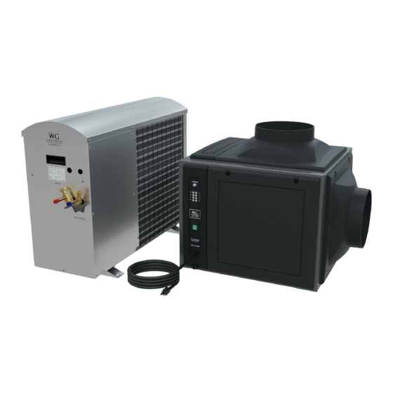
Ducted Split
Wine Cellar Cooling Systems
Installation, Operation and Maintenance Manual
60Hz Models: SP25, SP50, SP88, SP200
Manufactured by
Syracuse, NY
wineguardian.com
airinnovations.com
Wine Guardian reserves the right, without notice, to make changes to this document at its sole discretion.
Please visit our web site for the most current version of the Wine Guardian manual and other literature.
Wine Guardian is a registered trademark (2,972,262) of Air Innovations, Inc.
Edition 12/2021 (Original Instructions)
© Air Innovations 2021
15H0328-00
Part No.
1
Advertisement
Table of Contents

Related Manuals for Wine Guardian SP50


Summary of Contents for Wine Guardian SP50
- Page 1 Wine Guardian reserves the right, without notice, to make changes to this document at its sole discretion. Please visit our web site for the most current version of the Wine Guardian manual and other literature. Wine Guardian is a registered trademark (2,972,262) of Air Innovations, Inc.
-
Page 2: Table Of Contents
Terminal Strip Connections ......................13 Overview of the Condenser ......................14 Refrigeration Illustration ......................15 Wiring Diagram for SP25/SP50 (cont.) ..................17 Wiring Diagram for SP25 (cont.) ....................18 Wiring Diagram for SP50 (cont.) ....................19 Wiring Diagram for SP88 ........................20 Wiring Diagram for SP88 (cont.) .................... - Page 3 Installation of Interconnecting Refrigerant Lines ..............32 Refrigerant Line-Sets ........................33 Sample line Set Configurations ....................34 Leak Checking and Evacuation Process ................. 34 Wiring the Condenser ........................35 Start-Up ..............................36 Refrigerant Charging ........................36 Charging System with Head Pressure Control ..............36 Charge Amount: ..........................
-
Page 4: Safety
When performing maintenance, always use the Lockout/Tagout procedure, which is described in this chapter. Observe the maintenance safety guidelines in the Wine Guardian Manual. Electrical Hazards - Working on the equipment may involve exposure to dangerously high voltage. Make sure you are aware of the level of electrical hazard when working on the system. -
Page 5: Lockout/Tagout Procedure
When receiving the unit, ensure the unit is undamaged and includes all ordered accessories. Note: Wine Guardian units are factory assembled and tested prior to shipment. Wine Guardian units are shipped in individual corrugated boxes. ✓ Lift only at the designated handhold locations or fully support from underneath. A shipment may include one or more boxes containing accessories. -
Page 6: Directory Of Terms
• Grille or Diffuser – Inlet or outlet plates to direct the airflow or protect the inside of the unit. • Heat Gain / Loss – The amount of cooling or heating expressed in watts transferred between the wine cellar and the ambient space. The Wine Guardian must offset this load. -
Page 7: General Overview
All wiring complies with NEC. Each Wine Guardian fan coil section is furnished with a sealed, UL-approved power cord and plug. All Wine Guardian 50Hz units carry the CE mark. Each unit is furnished with a sealed, CE-approved power cord. - Page 8 ✓ Low ambient refrigeration controls (see page 9 for Extreme Climate Protection option). The Wine Guardian Pro Split System models meets or exceeds its rated capacities for total BTU/H and CFM at design cellar conditions and external static pressures. Both the evaporator and condenser fans are capable of achieving the rated CFM against the external static pressure imposed by recommended ductwork.
-
Page 9: Accessories/Options
Extreme Climate Protection This bundle includes both a factory-installed Low-Ambient-, and a factory-installed High- Ambient upgrade. Low-Ambient protection makes the Wine Guardian capable of exposure to low ambient temperatures. This feature controls the condenser fan operation based on head pressure and heats the oil reservoir, including a 3R Condenser Fan. - Page 10 Instructions. Duct Collar Kits Ductwork for the Wine Guardian system is sold in kits by size for each unit. Each kit contains two adapter collars, one 25-foot (7.3 meters) length of round flexible duct, and two straps. The number of duct kits needed depends on the installation layout. The size of the ductwork kit depends on the selected model of Wine Guardian system.
-
Page 11: Component Overview
Component Overview Cabinet – The cabinet (outer housing) is constructed of aluminum with a powder-coated finish for corrosion protection. Condensing Section – Ambient air is circulated through the condenser section by a direct drive, permanently lubricated, motorized impeller blower. This section also contains the compressor and the electrical controls. -
Page 12: Overview Of The Evaporator
Overview of the Evaporator Fig.1... -
Page 13: Terminal Strip Connections
Terminal Strip Connections White = Heat Cyan = 24 Volt AC Common Yellow = Cool Red = 24 Volt AC Power Green = Fan % = Humidity Connection Yc & Cc = Evaporator to Condenser 24 Volt Connection... -
Page 14: Overview Of The Condenser
Overview of the Condenser Fig. 2... -
Page 15: Refrigeration Illustration
Refrigeration Illustration Fig. 3... - Page 16 Wiring Diagram for SP25/SP50 Fig. 4 (SP25/SP50 Evap Molex connections)
-
Page 17: Wiring Diagram For Sp25/Sp50 (Cont.)
Wiring Diagram for SP25/SP50 (cont.) Fig. 5 (SP25/SP50 Control Assembly) -
Page 18: Wiring Diagram For Sp25 (Cont.)
Wiring Diagram for SP25 (cont.) Fig. 6 (DS025 Condenser) -
Page 19: Wiring Diagram For Sp50 (Cont.)
Wiring Diagram for SP50 (cont.) Fig. 7 (DS050 Condenser) -
Page 20: Wiring Diagram For Sp88
Wiring Diagram for SP88 Fig. 8 (SP88 Evap Molex connections) -
Page 21: Wiring Diagram For Sp88 (Cont.)
Wiring Diagram for SP88 (cont.) Fig. 9 (SP88 Control Assembly) -
Page 22: Wiring Diagram For Sp88 (Cont.)
Wiring Diagram for SP88 (cont.) Fig. 10 (DS088 Cond) -
Page 23: Wiring Diagram For Sp200
Wiring Diagram for SP200 Fig. 11 (SP200 Evap Molex connections) -
Page 24: Wiring Diagram For Sp200 (Cont.)
Wiring Diagram for SP200 (cont.) Fig. 12 (SP200 Control Assembly) -
Page 25: Wiring Diagram For Sp200 (Cont.)
Wiring Diagram for SP200 (cont.) Fig. 13 (DS200 Cond) -
Page 26: Specifications
Specifications Wine Guardian Specification Sheet – 60Hz models... -
Page 27: Installation
Install Fan-Coil Floor Mounting - Mount the Wine Guardian fan coil on the floor but elevate it 4” (10cm) as a minimum on a frame with a plywood surface to keep it away from water. Allow adequate space for the external drain. -
Page 28: Reducing Noise Generation
Ceiling Mounting - Construct a structurally sound, level platform to place the Evaporator on when hanging it from the ceiling joists. The Wine Guardian fan coil is NOT designed to be suspended from the top of the unit; it must be supported from the bottom. -
Page 29: Ductwork
Ductwork Wine Guardian units are typically installed indoors near the wine cellar to minimize duct runs. Each unit is provided with one entering (or return) air inlet and five possible supply air outlets for each of the evaporator and condenser sections. A maximum cumulative total length for both supply and return ducts (including bends) of 25 ft (7.5 meter) is... -
Page 30: Duct Collar And Panel Adjustment
Duct Collar and Panel Adjustment To replace or adjust the locations of the panels and Supply Collar please see the instructions below: 1. Determine which panel needs to be replaced (Fig 1). Fig. 1 2. Use a flat blade screwdriver, coin, or other suitable tool at the captive fastener (Fig 2). -
Page 31: Drain Line
Do NOT install an external trap on the drain line, every ducted Wine Guardian unit is built with an internal trap. Allow enough height for the drain line to function properly. If draining into a nearby sink, the unit must be elevated higher than the rim of the sink in order for the water to drain by gravity. -
Page 32: Installing The Condensing Unit
Do NOT modify the plugs in any way. Do NOT use extension cords. Depending on the model, the electrical power supply must be either 115-volt or 230-volt AC, 1 phase, 60 cycle, and the electrical power cannot vary more than ±4% or damage may occur to the unit. -
Page 33: Refrigerant Line-Sets
Model # Line (OD) Line (OD) Lift (height) Evaporator Evaporator Insulation Length (OD) (OD) Thickness 1/4” 1/4” 3/8” 3/8” 3/8” SP25 SP50 1/4" 1/4" 1/2" 3/8" *3/8" SP88 3/8" *1/4" 5/8" 5/8" *1/2" SP200 3/8" 3/8" 3/4" 5/8" *1/2" 50’... -
Page 34: Sample Line Set Configurations
Sample line Set Configurations Leak Checking and Evacuation Process • Pressurize and leak test the interconnecting lines, including the fan coil unit, fittings, and brazed joints using the intended operating refrigerant, nitrogen, or dry air for leak testing. A pressure equal to the low-side test pressure marked on the unit nameplate is recommended for leak testing. -
Page 35: Wiring The Condenser
optimal charging. Refer to page 39 of this manual for correct refrigerant charging based on your interconnect length. Charge the system with the correct amount of refrigerant and mark the amount with a ballpoint pen in the space provided on the unit nameplate. -
Page 36: Start-Up
Recommended Unit Minimum AWG SP25/SP50/SP88 SP200 Start-Up Prior to charging the system and start-up ensure the system has been powered for at least 24 hours. This is required so the compressor’s crankcase heater has ample time to warm the system to avoid premature failure. - Page 37 4. Charge refrigerant vapor into the low side. Do not allow liquid refrigerant into the low side. 5. Start the system. 6. Observe sight glass (factory-installed) to see if system is filling with refrigerant for normal refrigeration cycle. 7. If the Sight glass shows bubbles, more refrigerant may be required, while allowing sufficient time for the refrigerant to stabilize and clear the Sight glass.
- Page 38 With the system started • After following instructions on the previous page Charging for Systems with Head Pressure Control, with refrigerant tank now connected to suction line (low side) port to add remaining charge in a gas state, refer to the provided charts for proper system operating points as equated to ambient temperature with wine cellar at normal conditions of 57°F (13°C) / 55%RH.
-
Page 39: Charge Amount
For Installations using a line-set distance that are Greater Than 25’ add the required amount of refrigerant shown in the table below THEN add additional refrigerant based on the rules below: Models SP25 & SP50 Add an additional 0.50 oz/ft (0.465 kg/meter) for every foot exceeding 25’ Models SP88 & SP200 Add an additional 1 oz/ft (0.93 kg/meter) for every foot exceeding 25’... -
Page 40: Final Start-Up
100 ºF / 37 ºC 38 ºF / 21.11 ºC 19 ºF / 10.56 ºC 115 ºF / 46 ºC 40 ºF / 22.22 ºC 21 ºF / 11.67 ºC SP50 OD Ambient (F) Suction (psig) Discharge (psig) Suction Sub-cooling (F) Superheat (F) 20 ºF / -6 ºC... - Page 41 WG SPLIT SYSTEM START-UP CHECKLIST System Information Fan Coil Serial Number: Condenser Serial Number: (Located to the right of the main control panel) (Label located near refrigerant piping) Customer Information First Name: Last Name: Address: City: State: Zip: Date of Purchase: Email: Phone #: Installer Information...
- Page 42 Pre-Start-Up Is there any shipping damage? If so, Where? Will this damage prevent unit start-up? Check power supply. Does it agree with unit? Has the ground wire been connected? Has the circuit protection been sized and installed properly? Are the power wires to the unit sized and installed properly? Have compressor hold down bolts been loosened (snubber washers are snug, but not tight)? Controls...
-
Page 43: Maintenance
Risk of Serious Injury Sharp Edges are present on the fan wheels, housing, fins, and coils Maintenance on Wine Guardian units requires working with high voltage and sheet metal with possible sharp edges. Only qualified personnel should perform maintenance. Some tasks require knowledge of mechanical and electrical methods. Make sure you are familiar with all hazards, general safety related procedures, and safety labels on the unit. -
Page 44: Cleaning The Humidifier (Optional)
Cleaning the Humidifier (Optional) If the unit was furnished with a humidifier, it requires periodic maintenance. Follow the instructions in the humidifier guide. Electric Heat The heating coil is located between the evaporator coil and blower inside the transition duct. It contains the heating element and high-temperature-limit switches. The heating coil is wired to work in conjunction with the thermostat. -
Page 45: Yearly
Yearly (in addition to monthly) • Replace filters if worn or plugged beyond cleaning. • Check evaporator and condenser coils for dirt – use a vacuum with a brush attachment to clean the coils. • Clean condensate pan under the evaporator coil by flushing. Be careful to keep the drains pans clear of all debris. -
Page 46: Troubleshooting
Resetting the High-Pressure Switch High-Pressure Switch Has Shut Down the Unit Every Wine Guardian unit has a manual reset high-pressure switch in the refrigeration system. This switch shuts the compressor and condenser down if the head pressure in the system is too high. It is intended to protect the compressor. Restricted airflow through the condenser is the most common reason for the pressure to become too high. - Page 47 Fig. 1 Please see the link below for a video on how to reset the High-Pressure Switch https://www.youtube.com/watch?v=TFGFTWZVeAs...
-
Page 48: Contact And Warranty
Contact and Warranty GENERAL Wine Guardian warrants, to the original buyer, its goods, and all parts thereof to be free from defects in material and workmanship for a period of two (2) years from the date of invoicing assuming NORMAL USE AND SERVICE. -
Page 49: Contact Information
Warranty The Wine Guardian unit serial number is noted on all packing lists and bills of lading and, along with shipping date, is kept on file at Wine Guardian for warranty purposes. All correspondence regarding warranty must include the model number and serial number of the unit involved.
Need help?
Do you have a question about the SP50 and is the answer not in the manual?
Questions and answers