LS ELECTRIC SV-iS7 Series User Manual
Ac variable speed drive 0.75-75kw[200v] 0.75-375kw[400v]
Hide thumbs
Also See for SV-iS7 Series:
- User manual (300 pages) ,
- User manual (61 pages) ,
- User manual (39 pages)

Related Manuals for LS ELECTRIC SV-iS7 Series


Summary of Contents for LS ELECTRIC SV-iS7 Series
- Page 1 LS ELECTRIC strives to maximize your profits in gratitude for choosing us as your partner. AC Variable Speed Drive User’s Manual SV-iS7 series 0.75-75kW[200V] 0.75-375kW[400V]...
- Page 2 • SV-iS7 is the official name for the iS7 series inverters. • This operation manual is intended for users with basic knowledge of electricity and electric devices. • Keep this manual near the product for future reference whenever setting change, maintenance or service is required.
- Page 3 Safety Information Safety Information Read and follow all safety instructions in this manual precisely to avoid unsafe operating conditions, property damage, personal injury, or death. Safety symbols in this manual Indicates an imminently hazardous situation which, if not avoided, will result in severe injury or death.
- Page 4 Safety Information • This equipment must be grounded for safe and proper operation. • Do not supply power to a faulty inverter. If you find that the inverter is faulty, disconnect the power supply and have the inverter professionally repaired. •...
- Page 5 About This Manual Note [English] The maximum allowed prospective short-circuit current at the input power connection is defined in IEC 60439-1 as 100 kA. The drive is suitable for use in a circuit capable of delivering not more than 100 kA RMS at the drive’s maximum rated voltage, depending on the selected MCCB. RMS symmetrical amperes for recommended MCCB are the following table.
- Page 6 About This Manual About This Manual This operation manual describes the specifications of the SV-iS7 series inverters and provides detailed information required for the installation, operation, and maintenance of the products. This operation manual is intended for users with a basic knowledge of electricity and electric devices.
-
Page 7: Table Of Contents
Table of contents Table of Contents About the Product ......................1 Preparing for Installation and Operation ............1 1.1.1 Identifying the Product ................. 1 1.1.2 Checking the Product for Defects or Damage .......... 3 1.1.3 Preparing the Product for Installation and Operation ......3 1.1.4 Installing the Product .................. - Page 8 Table of contents 3.7.1 Disassembling the Keypad Cover and Keypad ........43 3.7.2 Disassembling the IP54 Front Cover ............44 3.7.3 Mounting the Inverter ................45 3.7.4 Connecting the Power Cables ..............46 3.7.5 Reassembling the IP54 Front Cover and the Keypad ......47 Connecting the Cables....................
- Page 9 Table of contents 4.12 Control Terminal Wiring for iS7 Extension I/O (Optional) ..... 76 4.13 Terminal Inputs for Inverter Operation ............77 4.14 Cable Specifications for Control Block Wiring ..........78 4.15 Setting the Built-in Surge Filter ..............79 4.16 Activating or Deactivating the Surge Filter ..........
- Page 10 Table of contents 6.5.1 Code Navigation in Monitor Mode ............123 6.5.2 Code Navigation (function items) in Other Modes and Groups ..124 6.5.3 Code Navigation Using Jump Code............125 Setting Parameters ..................127 6.6.1 Parameter Settings in Monitor Mode............ 127 6.6.2 Parameter Settings in Other Modes and Groups .......
- Page 11 Table of contents Reset and Restart ................... 164 7.10 Setting Acceleration and Deceleration Times .......... 165 7.10.1 Acc/Dec Time Based on Maximum Frequency ........165 7.10.2 Acc/Dec Time Based on Operation Frequency ........167 7.10.3 Multi-Step Acc/Dec Time Configuration ..........168 7.10.4 Configuring Acc/Dec Time Switch Frequency ........
- Page 12 Table of contents Up/down Operation ..................204 3-Wire Operation .................... 208 Safe Operation Mode ..................209 Dwell Operation ....................210 Slip Compensation Operation ..............212 PID Control ....................... 215 8.8.1 PID Basic Operation .................. 215 8.8.2 Pre-PID Operation ..................222 8.8.3 PID Sleep Mode ..................
- Page 13 Table of contents 8.30 User Group ...................... 268 8.31 Macro Selection ....................270 8.32 Easy Start ......................271 8.33 Config (CNF) Mode ..................272 8.34 Timer Settings ....................273 8.35 Auto Sequence Operation ................274 8.36 Traverse Operation ..................278 8.37 Brake Control ....................
- Page 14 Table of contents ........................313 Relay Output and Multi-function Output Terminal Settings ....314 Fault trip output using multi-function output terminals and relays ..320 Output Terminal Delay Time and Terminal Types ........321 9.6.1 Output Terminal Delay Time ..............321 9.6.2 Setting the Output Terminal Type............
- Page 15 Table of contents 11.5 Setting Operation Command and Frequency .......... 355 11.6 Command Loss Protection ................355 11.7 Setting Virtual Multi-Function inputs ............356 11.8 Saving Parameters Defined by Communication ........357 11.9 Communication Frame Monitoring ............358 11.10 Special communication Area Settings ............358 11.11 Parameter Group for Periodical Data Transmission .......
- Page 16 Table of contents 13.9 Parameter Mode – Auto Sequence Operation Group (AUT) ..... 431 13.10 Parameter Mode – Option Module Function Group (APO) ....434 13.11 Parameter Mode – Protective Function Group (PRT)......437 13.12 Parameter Mode – 2nd Motor Function Group (M2) ......440 13.13 Trip Mode (TRP Current (or Last-x)) ............
-
Page 18: About The Product
About the Product 1 About the Product This chapter provides details on product identification and part names. To install the inverter correctly and safely, carefully read and follow the instructions. 1.1 Preparing for Installation and Operation 1.1.1 Identifying the Product Check the product name, open the packaging, and then confirm that the product is free from defects. - Page 19 About the Product Note1) Optional conduit parts are available for the Enclosed UL Type 1 models (0.75–75 kW products). Note2) Optional built-in DCR is available for the Web application models (0.75–375 kW / type 2/4 products). Note3) To use safety function, please buy 0.75-160kW product including safety option. However 185-375kW product users have to buy safety option and apply to standard products because safety option is not included.
-
Page 20: Checking The Product For Defects Or Damage
About the Product 1.1.2 Checking the Product for Defects or Damage If you suspect that the product has been mishandled or damaged in any way, contact the LS ELECTRIC Customer Support center with the phone numbers listed on the back cover of this manual. -
Page 21: Part Names
About the Product 1.2 Part Names The illustration below displays part names. Details may vary between product groups. 1.2.1 Interior and Exterior View (IP 21 Model Types Less than 22 kW [200 V] / Less than 75 kW [400 V]) -
Page 22: Interior And Exterior View (Ip 54 Model Types Less Than 22 Kw [200/400 V])
About the Product 1.2.2 Interior and Exterior View (IP 54 Model Types Less than 22 kW [200/400 V]) -
Page 23: Interior And Exterior View (Model Types 30 Kw And Up [200 V] / 90 Kw And Up [400 V])
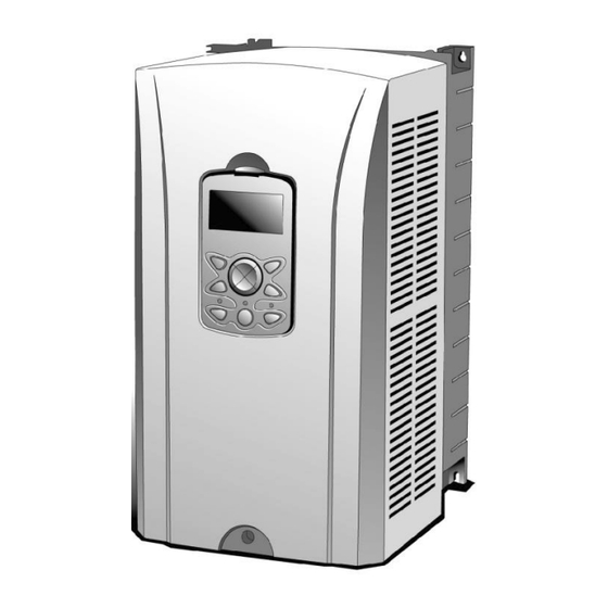
About the Product 1.2.3 Interior and Exterior View (Model Types 30 kW and up [200 V] / 90 kW and up [400 V]) Note Refer to the installation manual provided with the optional module products before installing communication modules in the inverter. -
Page 24: Technical Specifications
Technical Specifications 2 Technical Specifications 2.1 Input and Output Specifications 200 V Class (0.75– 22 kW) Model SV xxx iS7–2x 0008 0015 0022 0037 0055 0075 0110 0150 0185 0220 Normal load 18.5 Applied Motor Heavy load 0.75 18.5 Rated Capacity (kVA) 1.9 12.2 17.5 22.9 28.2... -
Page 25: Input And Output Specifications 200 V Class (30-75 Kw)
Technical Specifications 2.2 Input and Output Specifications 200 V Class (30– 75 kW) Model SV xxx iS7–2x 0300 0370 0450 0550 0750 Normal load Applied Motor Heavy load Rated Capacity (kVA) Normal Rated load Current Rated Heavy output load 0–400 Hz (Sensorless-1: 0–300 Hz, Sensorless-2, Vector: 0.1–120 Output Frequency Output Voltage (V) 3-Phase 200–230 V... -
Page 26: Input And Output Specifications 400 V Class (0.75-22 Kw)
Technical Specifications 2.3 Input and Output Specifications 400 V Class (0.75– 22 kW) Model SV xxx iS7–2x 0008 0015 0022 0037 0055 0075 0110 0150 0185 0220 Normal load 18.5 Applied Motor Heavy load 0.75 18.5 Rated Capacity 12.2 18.3 22.9 29.7 34.3... -
Page 27: Input And Output Specifications 400 V Class (30-160 Kw)
Technical Specifications 2.4 Input and Output Specifications 400 V Class (30– 160 kW) Model SV xxx iS7–2x 0300 0370 0450 0550 0750 0900 1100 1320 1600 Normal load Applied Motor Heavy load Rated Capacity (kVA) Normal Rated load Current Rated Heavy output load... -
Page 28: Input And Output Specifications 400 V Class (185-375 Kw)
Technical Specifications 2.5 Input and Output Specifications 400 V Class (185– 375 kW) Model SV xxx iS7–2x 1850 2200 2800 3150 3750 Normal load Applied Motor Heavy load Rated Capacity (kVA) 286 Normal Rated load Current Rated Heavy output load Output Frequency 0–400 Hz (Sensorless-1: 0–300 Hz, Sensorless-2, Vector: 0–120 Hz) Output Voltage (V) - Page 29 Technical Specifications Note [English] The maximum allowed prospective short-circuit current at the input power connection is defined in IEC 60439-1 as 100 kA. The drive is suitable for use in a circuit capable of delivering not more than 100 kA RMS at the drive’s maximum rated voltage, depending on the selected MCCB. RMS symmetrical amperes for recommended MCCB are the following table.
-
Page 30: Product Specification Details
Technical Specifications 2.6 Product Specification Details 2.6.1 Control Items Description V/F control, V/F PG, slip compensation, sensorless vector-1, Control modes sensorless vector-2, vector control Frequency Digital command: 0.01 Hz settings resolution Analog command: 0.06 Hz (maximum frequency: 60 Hz) Frequency Digital command: 0.01% of maximum output frequency Control accuracy... - Page 31 Technical Specifications Items Description • Leakage reduction • • Easy start Select NPN (Sink) or PNP (Source) mode. • Reverse direction • Forward direction operation operation • Reset • External trip • Emergency stop • Jog operation Multi- • Multi-step speed frequency- •...
-
Page 32: Protection Function
Technical Specifications 2.6.3 Protection Function Items Description • Over voltage • Low voltage • Lost command • Over current • Hardware failure • Earth current detection • Cooling fan failure • Inverter overheat Trips • Pre-PID failure • Motor overheat •... - Page 33 Technical Specifications Items Description No ice or frost should be present. Working under normal load at 50℃ (122F), it is recommended that less than 80% load is applied. • IP54 product: -10–40℃ No ice or frost should be present. Storage -20C–65C (-4–149F) temperature.
-
Page 34: Installing The Inverter
Installing the Inverter 3 Installing the Inverter 3.1 Installation Considerations Inverters are composed of various precision electronic devices, and therefore the installation environment can significantly impact the lifespan and reliability of the product. The table below details the ideal operation and installation conditions for the inverter. Items Description CT load (heavy duty): -10℃–50℃... -
Page 35: Selecting And Preparing A Site For Installation
Installing the Inverter Do not allow the ambient temperature to exceed the allowable range while operating the inverter. 3.2 Selecting and Preparing a Site for Installation When selecting an installation location, consider the following requirements: • The inverter must be installed on a wall that can support the inverter’s weight. •... - Page 36 Installing the Inverter Install the inverter on a non-flammable surface, and do not place flammable material near the inverter. Otherwise, a fire may result. Note Model types with capacities of 30 kW or more require a minimum of 8” clearance above and below the unit.
- Page 37 Installing the Inverter • Ensure that the cable conduits do not obstruct the air flow to and from the cooling fan. • Ensure sufficient air circulation is provided around the inverter when it is installed. If the inverter is to be installed inside a panel, enclosure, or cabinet rack, carefully consider the position of the inverter’s cooling fan and vents.
- Page 38 Installing the Inverter • If you are installing multiple inverters of different ratings, provide sufficient clearance to meet the clearance specifications of the larger inverter. The iS7 inverters rated for up to 30 kW may be installed side by side.
-
Page 39: Exterior And Dimensions (Ul Enclosed Type 1, Ip21 Type)
Installing the Inverter 3.3 Exterior and Dimensions (UL Enclosed Type 1, IP21 Type) SV0008-0037iS7 (200 V/400 V) Units: mm (inch) Inverter Capacity SV0008–0037 iS7 - 2/4 (5.90) (5.00) (11.18) (10.11) (0.70) (7.87) (0.19) (0.19) - Page 40 Installing the Inverter SV0055-0075iS7 (200 V/400 V) Units: mm (inch) Inverter Capacity SV0055–0075 iS7 - 2/4 (7.87) (6.92) (13.97) (12.87) (0.74) (8.85) (0.19) (0.19)
- Page 41 Installing the Inverter SV0110-0150iS7 (200 V/400 V) Units: mm (inch) Inverter Capacity SV0110–0150 iS7- 2/4 214.6 23.6 (9.84) (8.44) (15.15) (13.97) (0.92) (11.18) (0.25) (0.25)
- Page 42 Installing the Inverter SV0185-0220iS7 (200 V/400 V) Units: mm (inch) Inverter Capacity SV0185–0220iS7- 2/4 243.5 461.6 10.1 (11.02) (9.58) (18.17) (17.51) (0.39) (11.73) (0.25) (0.25)
- Page 43 Installing the Inverter SV0300-iS7 (200 V, IP00 Type) Units: mm (inch) Inverter Capacity 265.2 SV0300 iS7-2 (11.81) (7.48) (7.48) (22.44) (21.73) (0.39) (10.44) (0.39) (0.39)
- Page 44 Installing the Inverter SV0370-0450iS7 (200 V, IP00 Type) Units: mm (inch) Inverter Capacity SV0370–0450 281.2 iS7-2 (14.56) (10.63) (10.63) (24.8) (23.97) (0.43) (11.07) (0.39) (0.39)
- Page 45 Installing the Inverter SV0300-0450iS7 (400 V) Units: mm (inch) Inverter Capacity W1 DCR type 303.2 SV300–450 (11.93) (6.33) 300.1 242.8 594.1 24.1 iS7-4 (11.81) (9.55) (23.38) (22.12) (0.94) (0.39) (0.39) Non-DCR type 271.2 (10.67) (5.78)
- Page 46 Installing the Inverter SV0550-0750iS7 (200 V, IP00 Type) Units: mm (inch) Inverter Capacity SV0550–0750 723.5 15.5 355.6 iS7-2 (18.3) (15.0) (15.0) (29.52) (28.48) (0.61) (14.0) (0.43) (0.43)
- Page 47 Installing the Inverter SV0550-0750iS7 (400 V) Units: mm (inch) Inverter Capacity DCR type 373.3 211.5 SV0550–0750 (14.69) (8.32) 370.1 312.8 663.5 631.4 24.1 iS7-4 (14.57) (12.31) (26.12) (24.85) (0.94) (0.39) (0.39) Non-DCR type 312.4 150.6 (12.29) (5.92)
- Page 48 Installing the Inverter SV0900-1100iS7 (400 V, IP00 Type) Units: mm (inch) Inverter Capacity SV0900–1100 783.5 15.5 422.6 iS7-4 (20.07) (15.0) (13.77) (30.84) (29.88) (0.61) (16.63) (0.43) (0.43)
- Page 49 Installing the Inverter SV1320-1600iS7 (400 V, IP00 Type) Units: mm (inch) Inverter Capacity SV1320–1600 836.5 15.5 422.6 iS7-4 (20.07) (15.0) (13.77) (33.89) (32.93) (0.61) (16.63) (0.43) (0.43)
- Page 50 Installing the Inverter SV1850-2200iS7 (400 V, IP00 Type) Units: mm (inch) Inverter Capacity SV1850/ 1078 1043.5 25.5 2200iS7-4 (27.16) (22.87) (20.79) (42.44) (41.08) (1.00) (17.72) (0.55) (0.59)
- Page 51 Installing the Inverter SV2800iS7 (400 V, IP00 Type) Units: mm (inch) Inverter Capacity W1 1138 1110 SV2800iS7-4 (30.35) (19.69) (19.69) (44.80) (43.70) (0.59) (17.32) (0.51) (0.51) For 280 kW model types, I volts are supplied with the product.
- Page 52 Installing the Inverter SV3150-3750iS7 (400 V, IP00 Type) Units: mm (inch) Inverter Capacity W1 SV3150/ 1302.5 1271.5 3750iS7-4 (36.30) (22.83) (22.83) (51.28) (50.06) (0.59) (19.49) (0.55) (0.55) For 315-375 kW model types, I volts are supplied with the product.
-
Page 53: Exterior And Dimensions (Ul Enclosed Type 12, Ip54 Type)
Installing the Inverter 3.4 Exterior and Dimensions (UL Enclosed Type 12, IP54 Type) SV0008-0037iS7 (200 V/400 V) Units: mm (inch) Inverter Capacity 204.2 95.1 SV0008–0037 iS7-2/4 (8.03) (5.0) (16.49) (10.11) (3.74) (8.18) (0.19) (0.19) - Page 54 Installing the Inverter SV0055-0075iS7 (200 V/400 V) Units: mm (inch) Inverter Capacity 460.6 88.1 232.3 SV0055–0075 iS7-2/4 (10.0) (6.92) (18.13) (12.87) (3.46) (9.14) (0.19) (0.19)
- Page 55 Installing the Inverter SV0110-0150iS7 (200 V/400 V) Units: mm (inch) Inverter Capacity 313.1 214.6 590.8 101.7 294.4 SV0110–0150 iS7-2/4 (12.32) (8.44) (23.25) (13.97) (4.0) (11.59) (0.25) (0.25)
- Page 56 Installing the Inverter SV0185-0220iS7 (200 V/400 V) Units: mm (inch) Inverter Capacity 343.2 243.5 750.8 91.6 315.5 SV0185–0220 iS7-2/4 (13.51) (9.58) (29.55) (17.51) (3.60) (12.42) (0.25) (0.25)
-
Page 57: Frame Dimensions And Weight (Ul Enclosed Type 1, Ip 21 Type)
Installing the Inverter 3.5 Frame Dimensions and Weight (UL Enclosed Type 1, IP 21 Type) Weight[Kg] Weight[Kg] Weight[Kg] Weight[Kg] Inverter W[mm] H[mm] D[mm] w/ built-in w/ built-in w/ built-in non-DCR Capacity EMC and DCR types SV0008iS7-2/4 SV0015iS7-2/4 SV0022iS7-2/4 SV0037iS7-2/4 SV0055iS7-2/4 SV0075iS7-2/4 SV0110iS7-2/4 17.2... - Page 58 Installing the Inverter Weight[Kg] Weight[Kg] Weight[Kg] Weight[Kg] Inverter W[mm] H[mm] D[mm] w/ built-in w/ built-in w/ built-in non-DCR Capacity EMC and DCR types SV0300iS7-4 300.4 SV0370iS7-4 300.4 SV0450iS7-4 300.4 SV0550iS7-4 663.4 SV0750iS7-4 663.4 SV0900iS7-4 SV1100iS7-4 SV1320iS7-4 SV1600iS7-4 SV1850iS7-4 1078 SV2200iS7-4 1078 SV2800iS7-4 1138...
-
Page 59: Frame Dimensions And Weight (Ul Enclosed Type 12, Ip54 Type)
Installing the Inverter 3.6 Frame Dimensions and Weight (UL Enclosed Type 12, IP54 Type) Weight[Kg] Weight[Kg] Weight[Kg] Weight[Kg] Inverter W[mm] H[mm] D[mm] w/ built-in w/ built-in w/ built-in non-DCR Capacity EMC and DCR types SV0008iS7-2/4 SV0015iS7-2/4 SV0022iS7-2/4 SV0037iS7-2/4 SV0055iS7-2/4 12.8 10.2 12.1 SV0075iS7-2/4... -
Page 60: Installation Procedures For Ul Enclosed Type12 And Ip54 Type Products
Installing the Inverter 3.7 Installation Procedures for UL Enclosed Type12 and IP54 Type Products 3.7.1 Disassembling the Keypad Cover and Keypad Loosen the screws that secure the keypad cover and remove the keypad cover. Depress the tab at the top of the keypad and gently lift the keypad from the inverter to remove it. -
Page 61: Disassembling The Ip54
Installing the Inverter Depress the tab on the keypad cable connector and disconnect the cable from the back of the keypad. 3.7.2 Disassembling the IP54 Front Cover Loosen the screws that secure the front cover to the chassis. There are 9–13 screws on the cover depending on the model type. -
Page 62: Mounting The Inverter
Installing the Inverter Remove the cover by lifting it upwards from the bottom. 3.7.3 Mounting the Inverter Remove the 4 rubber feet from the corners. -
Page 63: Connecting The Power Cables
Installing the Inverter Place the inverter on a flat wall or in a cabinet, and use 4 screws or bolts to securely fix the inverter to the surface. 3.7.4 Connecting the Power Cables Connect the power cables to the input (R, S, T) and output (U, V, W) terminals. Then, tighten the terminal screws. -
Page 64: Reassembling The Ip54 Front Cover And The Keypad
Installing the Inverter 3.7.5 Reassembling the IP54 Front Cover and the Keypad Place the front cover on the chassis and align the screw holes on each side. Insert and tighten the screws. There are 9–13 screws on the cover depending on the model type. - Page 65 Installing the Inverter Connect the signal cable to the keypad, align the lower part of the keypad to the bottom of the keypad receptacle, and then push the top part of the keypad into the chassis until the keypad snaps into place. Place the keypad cover on top of the keypad, and secure it using 2 screws.
-
Page 66: Connecting The Cables
Connecting the Cables 4 Connecting the Cables Connect cables to the power and signal terminal blocks of the inverter. ESD (Electrostatic discharge) from the human body may damage sensitive electronic components on the PCB. Therefore, be extremely careful not to touch the PCB or the components on the PCB with bare hands while you work on the I/O PCB. - Page 67 Connecting the Cables Depress the tab on the keypad cable connector and disconnect the cable from the back of the keypad. Loosen the screw from the bottom part of the front cover, and then remove the front cover.
-
Page 68: Ip 54 Type Products
Connecting the Cables 4.1.2 IP 54 Type Products Loosen the two screws securing the keypad cover, and then remove the keypad cover. Depress the tab at the top of the keypad and gently lift the keypad from the inverter to remove it. -
Page 69: Kw, 400 V And 30-75 Kw, 200 V Products
Connecting the Cables Remove the screws from each side of the front cover, and then remove the front cover. 4.1.3 90–375 kW, 400 V and 30–75 kW, 200 V Products Loosen the two screws on the front cover. Slide the cover downwards and remove it from the inverter. -
Page 70: Activating And Deactivating The Built-In Emc Filter
Connecting the Cables 4.2 Activating and Deactivating the Built-in EMC Filter Some iS-7 inverter models have built-in EMC filters to reduce conductive and radiational noise at the inverter input. Refer to 1.1.1 Identifying the Product on page 1 and check your inverter’s model type and specifications to see if it has a built-in EMC filter. - Page 71 Connecting the Cables Connect the two jumper pins using a short circuit connector to activate the EMC filter. To remove the short circuit connector and deactivate the EMC filter, pull the connector while pressing the latch on the side of the connector. Use pliers or tweezers if you cannot reach the latch with your fingers.
-
Page 72: Kw Inverters
Connecting the Cables 4.2.2 11–22 kW Inverters Locate the EMC filter cable and the ground terminal at the bottom of the inverter. The EMC filter is deactivated if the EMC filter cable is connected to the insulated stud. <EMC filter is turned OFF> Remove the EMC filter cable from the insulated stud and connect it to the ground terminal (metal) to activate the EMC filter. - Page 73 Connecting the Cables Asymmetrical Grounding Connection Intermediate One phase of grounding a delta point on one connection is phase of a grounded delta connection A 3-phase The end of a connection single phase is without grounded grounding...
-
Page 74: Precautions For Wiring The Inverter
Connecting the Cables 4.3 Precautions for Wiring the Inverter • Do not connect power to the inverter until installation has been fully completed and the inverter is ready to be operated. Doing so may result in electric shock. • Wiring and inspection of wiring must be performed by an authorized engineer. •... -
Page 75: Ground Connection
Connecting the Cables 4.4 Ground Connection Install ground connections for the inverter and the motor by following the correct specifications to ensure safe and accurate operation. Using the inverter and the motor without the specified grounding connections may result in electric shock. •... -
Page 76: Terminal Wiring Diagram
Connecting the Cables 4.5 Terminal Wiring Diagram 4.5.1 Up to 7.5 kW Inverters R (L1) S (L2) T (L3) 3-phase AC input P (+) N (-) Dynamic brake To motor resistor 4.5.2 11–22 kW Inverters R (L1) S (L2) T (L3) P (+) N (-) 4.5.3 30–75 kW Inverters... -
Page 77: Kw Inverters
Connecting the Cables 4.5.5 185–220 kW Inverters R (L1) S (L2) T (L3) P2 (+) N (-) 4.5.6 280–375 kW Inverters R (L1) S (L2) T (L3) P1 (+) P2 (+) N (-) Note • Inverters with a rated capacity of 11 kW or more are equipped with linearly arranged terminal blocks. -
Page 78: Connecting Cables To The Power Terminal Block
Connecting the Cables 4.6 Connecting Cables to the Power Terminal Block Power supply cables must be connected to the R, S, and T terminals. Connecting power cables to other terminals will damage the inverter. Note The motor will rotate in the opposite direction if the U, V, and W terminals are connected in a wrong phase order. -
Page 79: Kw (200 V/400 V)
Connecting the Cables Cable connection for utilizing the optional dynamic braking unit Connect the cables from dynamic braking unit to P (+) and N (-) terminals to utilize the optional dynamic braking unit. Do not connect cables to B terminal. Terminal Symbol Terminal Name Description... -
Page 80: Kw (400 V)
U, V, W Inverter output terminals motor *Contact LS ELECTRIC Customer Support before configuring the P2 (+) and N (-) terminals as the DC common source. There are a few factors that require special attention for this application. Note External DC reactors cannot be used with 30–75 kW inverters. To use a DC reactor with these inverters, purchase a 30–75 kW inverter that has a built-in DC reactor. -
Page 81: Kw (400 V)
Connecting the Cables Terminal Symbol Terminal Name Description R (L1), S (L2), T (L3) AC power supply input terminals AC input terminals N (-) (-) DC voltage terminal (-) DC link voltage terminal P2 (+), N (-) Dynamic brake resistor terminal Dynamic brake resistor terminals Output terminals to a 3-phase U, V, W... -
Page 82: Kw (200 V/400 V)
U, V, W Inverter output terminals motor *Contact LS ELECTRIC Customer Support before configuring the P2 (+) and N (-) terminals as the DC common source. There are a few factors that require special attention for this application. • Apply rated torques to the terminal screws. Loose screws may cause the terminals to short circuit and malfunction. -
Page 83: Specifications Of The Power Terminal Block And Exterior Fuse
Connecting the Cables 4.7 Specifications of the Power Terminal Block and Exterior Fuse Cable Terminal Screw torque Exterior fuse Inverter capacity mm² AWG or kcmil screw size (Kgf· cm) R,S,T U,V,W R,S,T U,V,W Current Voltage 0.75 kW M4 7.1–12 10 A 500 V 1.5 kW 7.1–12... -
Page 84: Cable Length Between The Inverter And The Motor
Connecting the Cables Cable Exterior fuse Terminal Screw torque Inverter capacity mm² AWG or kcmil screw size (Kgf· cm) R,S,T U,V,W R,S,T U,V,W Current Voltage 182.4–215.0 220 kW 800 A 500 V 280 kW 182.4–215.0 1000 A 500 V 182.4–215.0 315 kW 2x200 2x200 2x400 2x400 1200 A... -
Page 85: Protective Measures For The Inverter And The Motor
Connecting the Cables a) If the output peak voltage is too high even when the motor cable length is shorter than the maximum recommended cable length for the inverter capacity: - use a motor with a high insulation rating. - install an output circuit filter (micro surge filter). - install a dv/dt filter, or a sine wave filter. -
Page 86: Control Terminal Wiring For Is7 Inverters Rated For Up To 22 Kw
Connecting the Cables Only use Class H or RK5 UL listed input fuses and UL listed breakers. See the table above for the voltage and current ratings for the fuses and breakers. Utiliser UNIQUEMENT des fusibles d’entrée homologués de Classe H ou RK5 UL et des disjoncteurs UL. -
Page 87: Npn Mode (Sink)
Connecting the Cables 4.8.1 NPN Mode (Sink) Select NPN using the PNP/NPN selection switch. The factory default setting is NPN mode. CM (24V GND) is the common ground terminal for all terminal inputs. 4.8.2 PNP Mode (Source) Select PNP using the PNP/NPN selection switch. The factory default setting is NPN mode. CM (24 V GND) is the common ground terminal for all terminal inputs, and 24 is the 24 V internal source. -
Page 88: 22 Kw (Basic I/O)
Connecting the Cables 4.8.3 0.75–22 kW (Basic I/O) Wiring Examples Default Functions Assigned for the Multi-Function Terminals Sp-L Sp-M Sp-H Note • The TR (termination resistor) switch is used to terminate the RS485 network connection (120 Ω). • For analog voltage input, use a potentiometer rated at 0.5W, 1kOhm. •... -
Page 89: Control Terminal Wiring For Is7 Inverters Rated For 30 Kw Or More
Connecting the Cables 4.9 Control Terminal Wiring for iS7 Inverters Rated for 30 kW or More 30–375 kW (control terminal block) -
Page 90: Terminal Inputs For Inverter Operation
Connecting the Cables Note • The TR (termination resistor) switch is used to terminate the RS485 network connection (120 Ω). • Use a potentiometer rated for 0.5 W, 1 kΩ. If the analog voltage (V) or current (I) input is used to set the frequency reference, the analog input is reflected when the input is actually received. - Page 91 Connecting the Cables Input Type Symbol Name Description Used to setup or modify a frequency reference via the analog voltage input terminal. Voltage input for Unipolar: 0–10 V frequency reference Bipolar: -10–10 V Input resistance 20 kΩ Used to setup or modify a frequency reference via Current input for the current input terminals.
-
Page 92: Cable Specifications For Control Block Wiring
Connecting the Cables 4.11 Cable Specifications for Control Block Wiring Cable size Terminal Name Specifications P1–P8 Multi-function input terminal Common terminal input Common earth for multi-function input (5G common is used for terminal analog frequency inputs only). Analog frequency setting (+) Output voltage: +12 V power 0.33–... -
Page 93: Control Terminal Wiring For Is7 Extension I/O (Optional)
Connecting the Cables 4.12 Control Terminal Wiring for iS7 Extension I/O (Optional) Extension I/O (control terminal block) -
Page 94: Terminal Inputs For Inverter Operation
Connecting the Cables 4.13 Terminal Inputs for Inverter Operation Input Type Symbol Name Description Configurable for multi-function input terminals. Multi-function Terminal P9–P11 Refer to 13 Table of Functions on page 399 for the input9–11 input multi-function terminal configurations. Common sequence Common terminal for terminal inputs Used to setup or modify a frequency reference via the analog voltage input terminal. -
Page 95: Cable Specifications For Control Block Wiring
Connecting the Cables 4.14 Cable Specifications for Control Block Wiring Cable size Terminal Name Specifications P9– Multi-function input terminal Common terminal input Common earth for multi-function input (5G common is used for terminal analog frequency inputs only). Multi-function analog voltage Input voltage: 0–10 V or -10–10 V input terminal Multi-function analog current... -
Page 96: Setting The Built-In Surge Filter
Connecting the Cables 4.15 Setting the Built-in Surge Filter The iS7 series inverters have a built-in surge filter between the input phases and the ground connection to absorb and mitigate surge current. This filter consists of a Y-CAP and multiple varistors. -
Page 97: Activating Or Deactivating The Surge Filter
4.16 Activating or Deactivating the Surge Filter 4.16.1 iS7 30–75KW (400 V) Inverters Contact LS ELECTRIC Customer Support and ask for assistance to deactivate the built-in surge filter for the 30–75 KW (400 V) inverters. 4.16.2 iS7 90–375 kW (400V) Inverters Remove the keypad and the screws from the front cover, and then remove the front cover. - Page 98 Connecting the Cables Refer to the following figures to locate the jumper switch on the SCR snubber board and install or remove the jumper cap to activate or deactivate the built-in surge filter. SV900-1600iS7 (400 V) SV1850-2200iS7 (400 V) SV2800-3750iS7 (400 V)
-
Page 99: Post-Installation Checklist
Connecting the Cables 4.17 Post-Installation Checklist After completing the installation, check the items in the following table to make sure that the inverter has been safely and correctly installed. Items Check Point Result Is the installation location appropriate? Does the environment meet the inverter’s operating conditions? Installation Location/Power Does the power source match the inverter’s rated input? -
Page 100: Test Run
Connecting the Cables Items Check Point Result defined prior to the installation of the control wiring connections? Are the control cables properly wired? Are the control terminal screws tightened to their specified torques? Is the total cable length of all control wiring < 328 ft (100 m) for model types rated at 3.7 kW and below, and 984 ft (300 m) for model types rated at more than 3.7 kW? Is the total length of safety wiring <... -
Page 101: Setting The Basic Parameters In Easy Start Mode
Connecting the Cables Note • Before setting the parameter values for a user application, initialize the parameter settings to make sure that the default setting is applied to all parameters. • If you initialized all parameters after an inverter trip occurred, the inverter starts in Easy Start mode after it is reset, regardless of the pending trip condition. -
Page 102: Checking The Inverter Operation
Connecting the Cables 4.18.3 Checking the Inverter Operation Using an inverter, you can easily operate a motor at a high speed. Before operating a motor using an inverter, ensure that the set speed is within the motor's rated speed. Follow the instructions to ensure that the motor operates correctly according to the inverter settings, and adjust the settings if required. -
Page 103: Peripheral Devices
Peripheral Devices 5 Peripheral Devices The reference diagram below shows a typical system configuration showing the inverter and peripheral devices. Prior to installing the inverter, ensure that the product is suitable for the application (power rating, capacity, etc.). Also, ensure that all of the required peripherals and optional devices (resistor brakes, contactors, noise filters, etc.) are available. -
Page 104: Wiring Switch, Electronic Contactor, And Reactor Specifications
Peripheral Devices 5.1 Wiring Switch, Electronic Contactor, and Reactor Specifications 5.1.1 Wiring Switch, Short Circuit Switch, and Electronic Contactor Wiring Switch Short Circuit Switch Electronic Contactor Inverter METASOL SUSOL Capacity Rated Rated Rated Rated Model Model Model Model current[A] current[A] current[A] current[A] 0008iS7-2 ABS33c... - Page 105 Peripheral Devices Wiring Switch Short Circuit Switch Electronic Contactor Inverter METASOL SUSOL Capacity Rated Rated Rated Rated Model Model Model Model current[A] current[A] current[A] current[A] 0900iS7-4 ABS403c UTS400 EBS403c MC-330a 1100iS7-4 ABS603c UTS600 EBS603c MC-400a 1320iS7-4 ABS603c UTS600 EBS603c MC-400a 1600iS7-4 ABS603c UTS600 EBS603c...
-
Page 106: Reactors
Peripheral Devices 5.1.2 Reactors DC Reactor Specifications The iS7 200 V/ 400 V 30–75 kW, 400 V/280–375 kW models are not supplied with a built-in DC reactor. Refer to the following specifications tables for different models to choose an appropriate DC reactor for your application. <200V/30–75kW>... - Page 107 Peripheral Devices AC Reactor Specifications You can install an AC reactor to prevent the capacitors and generators from overheating or being damaged when the power source voltage is unbalanced. When you install an AC reactor, connect the AC reactor cables to the R, S, and T terminals on the inverter.
- Page 108 Peripheral Devices AC reactor specifications Inverter capacity Heavy duty Normal duty 0015iS7-4 4.81 3.23 0022iS7-4 3.23 2.34 0037iS7-4 2.34 1.22 0055iS7-4 1.22 1.14 0075iS7-4 1.14 0.81 0110iS7-4 0.81 0.61 0150iS7-4 0.61 0.45 0185iS7-4 0.45 0.39 0220iS7-4 0.39 0.287 0300iS7-4 0.287 0.232 0370iS7-4 0.232...
-
Page 109: Dynamic Braking Unit (Dbu) And Resistor
Peripheral Devices 5.1.3 Dynamic Braking Unit (DBU) and Resistor Dynamic Braking Unit Specifications Reference- Capacity of Terminal UL form Type Voltage Braking unit applied motor arrangement & dimensions 30–37 kW SV370DBU-2U 200 V 45–55 kW SV550DBU-2U Type A 75 kW SV370DBU-2U, 2Set 30–37 kW SV370DBU-4U... - Page 110 LSLV2200DBU-4HN LSLV2200DBU-4HN, 280–375 kW 2Set Note 1) For model types with a rated capacity of 180 kW and above, contact LS ELECTRIC Customer Support for detailed information. Note • The 0.75–22kW (200 V/400 V) models are provided with a built-in dynamic braking unit.
- Page 111 Peripheral Devices Group 3 (75 kW DB unit) Group 4 (220 kW DB unit) Terminal Description Ground Terminal Connect to the B2 terminal of a braking resistor. Connect to the B1 terminal of a braking resistor. Connect to the N terminal of an inverter. Connect to the P terminal of an inverter.
- Page 112 Peripheral Devices Group 6 A frame (37 kW, 74 kW-4) B/C frame (75 kW-2, 90-220 kW) Terminal Description P (+) Connect to the P terminal of an inverter (DC bus). N ( - ) Connect to the N terminal of an inverter (DC bus). Connect to the B1 terminal of an external braking resistor.
-
Page 113: Db Unit Dimensions
Peripheral Devices DB Unit Terminal Description Connect to the B1 terminal of a DB resistor. Connect to the B2 terminal of a DB resistor. 5.1.4 DB Unit Dimensions Group 1... - Page 114 Peripheral Devices Group 2...
- Page 115 Peripheral Devices Group 3...
- Page 116 Peripheral Devices Group 4...
- Page 117 Peripheral Devices Group 5 Motor Voltage Dimensions (mm) Hole position Weight Hole size capacity [kW] [kg] (φ ) 1.50 1.55 1.57 1.84 227.4 76.4 215.4 1.53 1.55 1.56 1.85...
- Page 118 Peripheral Devices Group 6 Motor Hole Voltage Dimensions (mm) Hole position Weight capacity %ED size Frame [kW] [kg] (φ) 3.77 208.5 3.84 3.98 8.26 165.2 8.48 329.5 8.30 8.40 9.40 369.5 9.70...
-
Page 119: Indicators On The Db Unit
Peripheral Devices 5.1.5 Indicators on the DB unit On a DB unit, there are three LED indicators (one red and two green indicators) that indicate the operating condition of the DB unit. Indicator Color Location Description name Turns on when the main power is supplied to the unit (if a DB Power Middle unit is connected to an inverter, the power indicator is turned... - Page 120 Peripheral Devices Inverter Resistance Wattage Wiring Type Reference Model Type capacity (kW) [ohm] 0.75 1.25 1.25 TYPE 1 MCRF400W50 TYPE 2 MCRF600W33 150% TYPE 3 MCRF800W20 braking torque, 1200 TYPE 5 MCRF1200W15 5%ED 2400 TYPE 6 MCRF-ST2400W10 2400 TYPE 6 MCRF-ST2400W8 18.5 3600...
- Page 121 Peripheral Devices Inverter Resistance Wattage Wiring Type Reference Model Type capacity (kW) [ohm] 25,000 30,000 30,000 40,000 60,000 60,000 • If you install multiple DB units in parallel, the combined resistance value must match the resistance value in the table above. •...
-
Page 122: Db Resistor Dimensions
Peripheral Devices 5.1.7 DB Resistor Dimensions TYPE 1,2,3,4,5 (Maximum 1200 Watts) Size [mm] TYPE TYPE 6 (Maximum 2400 Watts) -
Page 123: Keypad Extension Cable For Remote Control (Optional)
Peripheral Devices TYPE 7 (Maximum 3600 Watts) 5.1.8 Keypad Extension Cable for Remote Control (Optional) Included items Items Keypad bracket Remote cable (2 m/3 m) - Page 124 Peripheral Devices Keypad Bracket Dimensions Remote Cable Specifications Model type Part name 64110009 INV, iS7 REMOTE CABLE (2 M) 64110010 INV, iS7 REMOTE CABLE (3 M)
- Page 125 Peripheral Devices Installing the Remote Cable Refer to the following figure to install the remote cable to extend the keypad cable length. If a “Line Check” message is displayed on the keypad display and the keypad is not operating correctly after installing the remote cable, check the cable connection on both sides. Do not extend the keypad cable using a third-party extension cable.
-
Page 126: Using The Keypad
Using the Keypad 6 Using the Keypad 6.1 About the Keypad A keypad is used to set inverter parameters, monitor the inverter’s status, and operate the inverter. 6.1.1 Dimensions... -
Page 127: Key Functions
Using the Keypad 6.1.2 Key Functions The following table lists the names and functions of the keypad’s operation keys. Section Buttons Key Name Function Description [MODE] key Used to switch between modes. If this button is pressed once, the parameter can be edited at the status of the editable parameter code. -
Page 128: Display Items
Using the Keypad 6.1.3 Display Items Monitor Mode Parameter Mode 6.1.4 Display Item List The following table lists the items in the display. Item Description Displays the current mode’s display items. For more details, refer Mode display items to 6.3 Navigating Modes on page 117. - Page 129 Using the Keypad Item Description Displays the current parameter group’s items. For more details, Parameter group items refer to 6.4 Navigating Modes and Parameters on page 120. Command source / Displays the types of sequences and the number of steps during an frequency reference items auto sequence operation.
- Page 130 Using the Keypad Function Display Description Jog frequency command Internal 485 frequency command 1-9 A-F Multi-step frequency command JOG key Used to switch to Keypad JOG mode Local/Remote Used to select local or remote operation Multi-function Used to register parameters as a user group in key settings User Group Parameter mode or delete parameters in the user...
-
Page 131: Menu Items
Using the Keypad 6.2 Menu Items The SV-iS7 series inverter uses 5 modes to monitor or configure different functions. Each mode has its own function items suitable for the desired properties. The parameters in Parameter mode and User & Macro mode are divided into smaller groups of relevant functions. -
Page 132: Parameter Mode
Using the Keypad Mode Display Description Displays the inverter’s operation status information. You can Monitor mode monitor the frequency setting, operating frequency display, output current, voltage, etc. Used to configure the functions required to operate the inverter. Parameter mode These functions are divided into 12 groups based on purpose and complexity. -
Page 133: User & Macro Mode
Using the Keypad Mode Display Description Output terminal Configures the inverter output terminal block-related features, function group including the relay and analog outputs. Communication Configures the communication features for the RS-485, if one is function group installed. Application Configures the features related to PID control and auto sequence function group operation. -
Page 134: Navigating Modes
Using the Keypad 6.3 Navigating Modes 6.3.1 Mode Navigation at the Factory Default You can change the display to navigate modes by using the [MODE] key. The User & Macro Mode and Trip Mode are not displayed when the inverter is set to the factory default settings. For more details, refer to 11.12 Parameter Group for Transmission of Macro Group and User Group at U&M Mode on page 361. -
Page 135: Mode Navigation With User/Macro Mode And Trip Mode
Using the Keypad • You are now in Parameter mode (PAR). • Press the [MODE] key. • You are now in Config mode (CNF). • Press the [MODE] key. • You are now in Monitor mode again. 6.3.2 Mode Navigation with User/Macro Mode and Trip Mode If you register a user code or set the macro function using the [MULTI] key, the User &... - Page 136 Using the Keypad • You are now in Parameter mode (PAR). • Press the [MODE] key. • You are now in User & Macro mode (U&M). • Press the [MODE] key. • You are now in Trip mode (TRP). • Press the [MODE] key.
-
Page 137: Navigating Modes And Parameters
Using the Keypad 6.4 Navigating Modes and Parameters You can navigate modes by using the [Left] or [Right] keys after navigating to the Parameter Mode or User & Macro Mode via the [Mode] key. 6.4.1 Group Navigation in Parameter mode If you press the [Right] key in Parameter mode, the display will change as shown below. - Page 138 Using the Keypad • You are now in Parameter mode (PAR). • The Drive Group (DRV) of Parameter mode is displayed. • Press the [Right] key. • You are now in the Basic Function Group (BAS). • Press the [Right] key. •...
-
Page 139: Group Shift In User & Macro Mode
Using the Keypad 6.4.2 Group Shift in User & Macro Mode To navigate to User & Macro Mode, the user code should be registered or the macro function should be selected. For more details on how to register the user code and macro group, refer to 11.12 Parameter Group for Transmission of Macro Group and User Group at U&M Mode on page 361. -
Page 140: Navigating Through Codes (Function Items)
Using the Keypad 6.5 Navigating through Codes (Function Items) 6.5.1 Code Navigation in Monitor Mode To display the frequency, output current, and output voltage, press the [Up] or [Down] keys to scroll through the items. • Displays when the inverter is powered on. This display is in Monitor mode. -
Page 141: Code Navigation (Function Items) In Other Modes And Groups
Using the Keypad • The output voltage text has disappeared and the cursor has moved to the third display item. • Press the [Up] key twice. • The first item displays the frequency. • The frequency text has disappeared and the cursor has moved to the first display item. -
Page 142: Code Navigation Using Jump Code
Using the Keypad • Displays the Drive (DRV) group of Parameter mode. If the DRV group is not displayed, press the [MODE] key until the DRV group appears, or press the [ESC] key. • If you press the [Down] key, you will navigate to code No. - Page 143 Using the Keypad • The cursor flashes and you can enter the code number. • Press the [Up] key to enter 9 and then press the [PROG/ENT] key. • You have moved to code No. 09 of the DRV group. •...
-
Page 144: Setting Parameters
Using the Keypad 6.6 Setting Parameters 6.6.1 Parameter Settings in Monitor Mode You can set some parameters, such as the frequency, in Monitor mode. The following example demonstrates how to set the frequency. • Ensure that the cursor is at the frequency item. Also, ensure that the frequency can be set to 09 in the Drive (DRV) group using the keypad. -
Page 145: Parameter Settings In Other Modes And Groups
Using the Keypad 6.6.2 Parameter Settings in Other Modes and Groups The following example demonstrates how to change the frequency of the Drive (DRV) group in Parameter mode. The frequency in the other modes or groups can be set as follows. •... -
Page 146: Monitoring Operating Status
Using the Keypad 6.7 Monitoring Operating Status 6.7.1 Using Monitor Mode Three items can be displayed in Monitor mode at a time. Also, some items, such as the frequency item, can be edited. You can select the displayed items in Configuration (CNF) mode. •... -
Page 147: Monitoring Items
Using the Keypad 6.7.2 Monitoring Items Mode Code Function Display Setting Range Initial Value Anytime Para Frequency 0: Frequency Monitor Line-1 Speed 0: Frequency Monitor Line-2 Output Current 2:Output Current Output Voltage Output Power WHour Counter DCLink Voltage DI Status DO Status V1 Monitor [V] V1 Monitor [%]... -
Page 148: Using The Status Display
Using the Keypad 6.7.3 Using the Status Display The items displayed on the right-top of the display are shown in other modes, including Monitor mode. If you register a desired variable in the display, you can monitor it at any time regardless of the mode navigation or change. -
Page 149: Monitoring Faults
Using the Keypad 6.8 Monitoring Faults 6.8.1 Faults during Inverter Operation • If a fault trip occurs during inverter operation, the inverter enters Trip mode automatically and displays the type of fault trip that has occurred. • Press the [Down] key to view the information on the inverter at the time of the fault, including the output frequency, current, and operating status. -
Page 150: Multiple Faults At A Time During Inverter Operation
Using the Keypad 6.8.2 Multiple Faults at a Time during Inverter Operation • If multiple fault trips occur at the same time, the number of fault trips that occurred is displayed next to the fault trip type. • Press the [PROG/ENT] key. •... - Page 151 Using the Keypad • If a fault trip occurs during inverter operation, the inverter enters Trip mode and displays the type of fault trip that has occurred. • If you press the [STOP/RESET] key or an input is entered on the terminal, the fault trip is automatically saved and the display status that was displayed before the fault trip occurred is displayed.
-
Page 152: Initializing Parameters
Using the Keypad 6.9 Initializing Parameters You can initialize the changed parameters. In addition to initializing the entire parameter, you can also select the individual parameter mode to be initialized. • Monitor mode is displayed. • Press the [MODE] key to move to Configuration (CNF) mode. - Page 153 Using the Keypad • The Parameter Initialization option is displayed again when the initialization is complete.
-
Page 154: Basic Functions
Basic Functions 7 Basic Functions 7.1 Setting Frequency References The iS7 inverter provides several methods to set up and modify a frequency reference for an operation. The keypad, analog inputs [for example voltage (V1) and current (I1) signals], or RS- 485 (digital signals from higher-level controllers, such as PCs or PLCs) can be used. -
Page 155: Keypad As The Source (Keypad-1 Setting)
Basic Functions 7.1.1 Keypad as the Source (KeyPad-1 setting) You can modify the frequency reference using the keypad and apply changes by pressing the [ENT/PROG] key. To use the keypad as a frequency reference input source, go to DRV-07 (Frequency reference source) and change the parameter value to “0 (Keypad-1)”. Input the frequency reference for an operation at DRV-01 (Frequency reference). - Page 156 Basic Functions 7.1.3.1 Setting a Frequency Reference for 0–10 V Input Set IN-06 (V1 Polarity) to “0 (unipolar)”. Use a voltage output from an external source or use the voltage output from the VR terminal to provide inputs to V1. Refer to the diagrams below for the wiring required for each application.
- Page 157 Basic Functions 0–10 V Input Voltage Setting Details Code Description Configures the frequency reference at the maximum input voltage when a potentiometer is connected to the control terminal block. A frequency set with code IN-01 becomes the maximum frequency only if the value set in code IN- 11 (or IN-15) is 100%.
- Page 158 Basic Functions Code Description Inverts the direction of rotation. Set this code to “1 (Yes)” if you need the motor IN-16 V1 Inverting to run in the opposite direction from the current rotation. Quantizing may be used when the noise level is high in the analog input (V1 terminal) signal.
- Page 159 Basic Functions Code Description [V1 Quantizing]...
- Page 160 Basic Functions 7.1.3.2 Setting a Frequency Reference for -10–+10 V Input Set DRV-07 (Frequency reference source) to “2 (V1)”, and then set IN-06 (V1 Polarity) to “1 (bipolar)”. Use the output voltage from an external source to provide an input to V1. [External source application] [Internal source (VR) application] [V1 terminal wiring]...
- Page 161 Basic Functions Group Code Name LCD Display Parameter Setting Setting Range Unit V1 input monitor V1 Monitor 0.00 0.00–10.00 V V1 polarity options V1 Polarity Bipolar 0–1 V1 minimum input V1- volt x1 0.00 0.00–10.00 V voltage V1 output at V1- Perc y1 0.00 -100.00–0.00%...
- Page 162 Basic Functions Code Description For details about the 0–+10 V analog inputs, refer to the code descriptions IN- 08 V1 volt x1–IN-11 V1 Perc y2 on page 143...
- Page 163 Basic Functions 7.1.3.3 Setting a Reference Frequency using Input Current (I1) You can set and modify a frequency reference using input current at the I1 terminal. Set DRV- 07 (Frequency reference source) to “3 (I1)” and apply an input current of 0–20 mA to I1. Group Code Name LCD Display Parameter Setting...
- Page 164 Basic Functions Input Current (I1) Setting Details Code Description Configures the frequency reference for operation at the maximum current (when IN-26 is set to 100%). • If IN-01 is set to 40.00, and default settings are used for IN-23–26, an IN-01 Freq at input current of 20 mA (max) to I1 will produce a frequency reference of 100%...
-
Page 165: Setting A Frequency Reference Using An I/O Expansion Module (Terminal V2/I2)
Basic Functions 7.1.4 Setting a Frequency Reference Using an I/O Expansion Module (Terminal V2/I2) After installing an optional I/O I/O expansion moduleto the iS7 inverter, you can set and modify a frequency reference using the input voltage or current at the V2/I2 terminal. 7.1.4.1 Setting a Reference Frequency using Input Voltage at V2 Terminal Set the DRV-07 (Frequency reference source) to “4 (V2)”... - Page 166 Basic Functions Group Code Name LCD Display Parameter Setting Setting Range Unit maximum V2’ voltage Invert V2 rotational V2 Inverting No/Yes direction 0.00*, 0.04– V2 quantizing level 0.04 Quantizing 10.00 * Quantizing is disabled if “0” is selected. 7.1.4.2 Setting a Reference Frequency using Input Current at I2 Terminal Set the DRV-07 (Frequency reference source) to “5 (I2)”...
-
Page 167: Setting A Frequency With Pulse Input (With An Optional Encoder Module)
Basic Functions 7.1.5 Setting a Frequency with Pulse Input (with an optional encoder module) After installing an optional encoder module, you can set a frequency reference by setting DRV- 07 (Frequency reference source) to “9 (Pulse)” and providing a pulse frequency of 0–32.00 kHz to the pulse input terminal. - Page 168 Basic Functions Pulse Input Setting Details Code Description APO-01 Enc Opt Sets the encoder option mode. Set APO-01 to “2 (Reference)” to receive a Mode pulse input for the frequency reference. APO-04 Enc Type Sel Sets the output type. APO-05 Enc Pulse Selects the encoder pulse to use.
-
Page 169: Setting A Frequency Reference Via Rs-485 Communication
Basic Functions 7.1.6 Setting a Frequency Reference via RS-485 Communication Control the inverter with upper-level controllers, such as PCs or PLCs, via RS-485 communication. Set DRV-07 (Frequency reference source) to “6 (Int 485)” and use the RS-485 signal input terminals (S+/S-/SG) for communication. For more details, refer to 11 Communication Function on page 351. -
Page 170: Frequency Hold By Analog Input
Basic Functions 7.2 Frequency Hold by Analog Input If you set a frequency reference via the analog input at the control terminal block, you can hold the operation frequency of the inverter by assigning a multi-function input as the analog frequency hold terminal. -
Page 171: Changing The Displayed Units (Hz↔Rpm)
Basic Functions 7.3 Changing the Displayed Units (Hz↔Rpm) You can change the units used to display the operational speed of the inverter by setting DRV- 21 (Speed unit selection) to “0 (Hz Display)” or “1 (Rpm Display)”. Group Code Name LCD Display Parameter Setting Setting Range... - Page 172 Basic Functions Multi-step Frequency Setting Details Code Description BAS Group 50–64 Configure multi-step frequency 1–15. Choose the terminals to set up as multi-step inputs, and then set the relevant codes (IN-65–75) to 7 (Speed-L), 8 (Speed-M), 9 (Speed-H), or 10 (Speed-X). Provided that terminals P6, P7, and P8 have been set to Speed-L, Speed-M and Speed-H respectively, the following multi-step operation will be available.
- Page 173 Basic Functions Code Description the highest bit is Speed-X. Speed Fx/Rx ...
-
Page 174: Command Source Configuration
Basic Functions 7.5 Command Source Configuration Various devices can be selected as command input devices for the iS7 inverter. Input devices available include the keypad, multi-function input terminal, RS-485 communication, and field bus adapter. Group Code Name LCD Display Parameter Setting Setting Range Unit Keypad... -
Page 175: The Terminal Block As A Command Input Device (Fwd/Rev Run Commands)
Basic Functions 7.5.2 The Terminal Block as a Command Input Device (Fwd/Rev run commands) Multi-function terminals can be selected as a command input device. This is configured by setting DRV-06 (command source) to “1 (Fx/Rx-1)”. Select two terminals for the forward and reverse operations, and then set the relevant codes (2 of the 11 multi-function terminal codes, IN-65–75 for P1–P8 [optional: P9–P11]) to “1 (Fx)”... -
Page 176: The Terminal Block As A Command Input Device (Run And Rotation Direction Commands)
Basic Functions 7.5.3 The Terminal Block as a Command Input Device (Run and Rotation Direction Commands) Multi-function terminals can be selected as a command input device. This is configured by setting DRV-06 (command source) to “2 (Fx/Rx-2)”. Select two terminals for run and rotation direction commands, and then set the relevant codes (2 of the 11 multi-function terminal codes, IN-65–75 for P1–P11 [optional: P9–P11]) to “1 (Fx)”... -
Page 177: Communication As A Command Input Device
Basic Functions 7.5.4 RS-485 Communication as a Command Input Device Internal RS-485 communication can be selected as a command input device by setting DRV-06 (command source) in the Drive group to “3 (Int 485)”. This configuration uses upper level controllers, such as PCs or PLCs, to control the inverter by transmitting and receiving signals via the S+, S-, and RS-485 signal input terminals at the terminal block. - Page 178 Basic Functions Group Code Name LCD Display Parameter Setting Setting Range Unit [MULTI] key Multi-Key Sel 2 Local/Remote functions Command source Cmd Source 1 Fx/Rx-1 0–5 Local/Remote Mode Switching Setting Details Code Description Set CNF-42 to “2(Local/Remote)” to perform local/remote mode switching using the [MULTI] key.
-
Page 179: Forward Or Reverse Run Prevention
Basic Functions - Pre-excitation terminal To operate the inverter manually with the keypad, switch to local mode. Use caution when switching back to remote operation mode as the inverter will stop operating. If ADV-10 (power- on run) is set to “0 (No)”, a command through the input terminals will work only after all the terminals listed above have been turned off and then turned on again. -
Page 180: Power-On Run
Basic Functions Forward/Reverse Run Prevention Setting Details Code Description Choose a direction to prevent. Setting Description ADV-09 Run None Do not set run prevention. Prevent Forward Prev Set forward run prevention. Reverse Prev Set reverse run prevention. 7.8 Power-on Run The Power-on Run feature can be set up to start an inverter operation after powering up based on the run commands by terminal inputs (if they are configured). -
Page 181: Reset And Restart
Basic Functions Note • To prevent a repeat fault trip from occurring when a load, such as a fan, is free-running on a Power-on Run, set CON-71 (speed search options) bit 4 to “1”. The inverter will perform a speed search at the beginning of the operation. -
Page 182: Setting Acceleration And Deceleration Times
Basic Functions Group Code Name LCD Display Parameter Setting Setting Range Unit Auto restart delay Retry Delay 0–60.0 time Note • To prevent a repeat fault trip from occurring, set the CON-71 (Speed search options) bit 2 to “1”. The inverter will perform a speed search at the beginning of the operation. If the speed search is not enabled, the inverter will start its operation in a normal V/F pattern and accelerate the motor. - Page 183 Basic Functions Group Code Name LCD Display Parameter Setting Setting Range Unit frequency Acc/Dec Max Freq/Delta Ramp T Mode Max Freq reference Freq Time scale Time scale 0–2 (0.01/0.1/1) Acc/Dec Time Based on Maximum Frequency – Setting Details Code Description Set BAS-08 to “0 (Max Freq)”...
-
Page 184: Acc/Dec Time Based On Operation Frequency
Basic Functions 7.10.2 Acc/Dec Time Based on Operation Frequency Acc/Dec times can be set based on the time required to reach the next frequency from the existing operation frequency. To set the acc/dec time values based on the existing operation frequency, set BAS-08 (Acc/Dec reference) to “1 (Delta Freq)”. -
Page 185: Multi-Step Acc/Dec Time Configuration
Basic Functions 7.10.3 Multi-Step Acc/Dec Time Configuration The acc/dec times can be configured via a multi-function terminal by setting the ACC (acceleration time) and DEC (deceleration time) codes in the DRV group. Group Code Name LCD Display Parameter Setting Setting Range Unit 75 kW and less 20.0 Acceleration time... -
Page 186: Configuring Acc/Dec Time Switch Frequency
Basic Functions Code Description acc/dec commands are recognized as binary code inputs and will control the acceleration and deceleration based on parameter values set at BAS-70–75 If, for example, the P7 and P8 terminals are set as XCEL-L and XCEL-M respectively, the following operation will be available. - Page 187 Basic Functions Group Code Name LCD Display Parameter Setting Setting Range Unit Multi-step Dec Time-1 20.0 0.0–600.0 deceleration time1 Acc/dec time 0–Maximum Xcel Change Fr 30.00 Hz/RPM switch frequency frequency Acc/Dec Time Switch Frequency Setting Details Code Description After the acc/dec switch frequency has been set, the acc/dec gradients configured at BAS-70 and 71 will be used when the inverter’s operation frequency is at or below the switch frequency.
-
Page 188: Acc/Dec Pattern Configuration
Basic Functions 7.11 Acc/Dec Pattern Configuration The acc/dec gradient level patterns can be configured to enhance and smooth out the inverter’s acceleration and deceleration curves. A linear pattern features a linear increase or decrease to the output frequency, at a fixed rate. An S-curve pattern offers a smoother and more gradual increase or decrease of output frequency, ideal for lift-type loads or elevator doors, etc. - Page 189 Basic Functions Code Description pattern. ADV-03 defines S-curve gradient level as a percentage, above half of the total acceleration. If the frequency reference and the maximum frequency are set at 60 Hz and ADV-04 is set to 50%, setting ADV-04 configures acceleration to increase from 30 Hz (half of 60 Hz) to 60 Hz (end of acceleration).
- Page 190 Basic Functions [Acceleration / deceleration S-curve pattern configuration] Note The actual acc/dec time during an S-curve application The actual acceleration time = user-configured acceleration time + user-configured acceleration time x starting gradient level/2 + user-configured acceleration time x ending gradient level/2. The actual deceleration time = user-configured deceleration time + user-configured deceleration time x starting gradient level/2 + user-configured deceleration time x ending gradient level/2.
-
Page 191: Stopping The Acc/Dec Operation
Basic Functions 7.12 Stopping the Acc/Dec Operation Configure the multi-function input terminals to stop acceleration or deceleration and operate the inverter at a fixed frequency. Group Code Name LCD Display Parameter Setting Setting Range Unit Px terminal Px Define (Px: P1–P8 65–75 XCEL Stop 0–51... -
Page 192: V/F (Voltage/Frequency) Control
Basic Functions 7.13 V/F (Voltage/Frequency) Control Configure the inverter’s output voltages, gradient levels, and output patterns to achieve a target output frequency with the V/F control. The amount of torque boost used during low frequency operations can also be adjusted. 7.13.1 Linear V/F Pattern Operation A linear V/F pattern configures the inverter to increase or decrease the output voltage at a fixed rate for different operation frequencies based on V/F characteristics. -
Page 193: Square Reduction V/F Pattern Operation
Basic Functions 7.13.2 Square Reduction V/F Pattern Operation Square reduction V/F pattern is ideal for loads such as fans and pumps. It provides non-linear acceleration and deceleration patterns to sustain torque throughout the entire frequency range. Group Code Name LCD Display Parameter Setting Setting Range Unit... -
Page 194: User V/F Pattern Operation
Basic Functions 7.13.3 User V/F Pattern Operation The iS7 inverter allows the configuration of user-defined V/F patterns to suit the load characteristics of a specific motor. Group Code Name LCD Display Parameter Setting Setting Range Unit V/F pattern V/F Pattern User V/F 0–2 0–Maximum... - Page 195 Basic Functions The 100% output voltage in the figure below is based on the parameter settings of BAS-15 (motor rated voltage). If BAS-15 is set to “0,” it will be based on the input voltage. • When a normal induction motor is in use, care must be taken not to change the output pattern from a linear V/F pattern.
-
Page 196: Torque Boost
Basic Functions 7.14 Torque Boost 7.14.1 Manual Torque Boost Manual torque boost enables users to adjust the output voltage during low-speed operation or motor start. You can increase the low-speed torque or improve motor-starting properties by manually increasing the output voltage. Configure the manual torque boost while running loads that require a high starting torque, such as lift-type loads. -
Page 197: Auto Torque Boost
Basic Functions Excessive torque boost will result in over-excitation and motor overheating. 7.14.2 Auto Torque Boost Set DRV-15 to “1 (Auto)” to enable auto torque boost. While manual torque boost adjusts the inverter output based on the setting values, regardless of the type of load used during the operation, auto torque boost enables the inverter to automatically calculate the amount of output voltage required for the torque boost based on the entered motor parameters. - Page 198 Basic Functions Group Code Name LCD Display Parameter Setting Setting Range Unit Rev Boost Note2) Rev Boost 0-15 Adv ATB Filter Adv ATB Filter 1-1000 msec Adv ATB M Gain Adv ATB M Gain 50.0 0-300.0 Adv ATB G Gain Adv ATB G Gain 50.0 0-300.0...
-
Page 199: Output Voltage Setting
Basic Functions If the torque boost amount is set too large, overheating of the motor due to over-excitation will occur. 7.15 Output Voltage Setting Output voltage settings are required when a motor’s rated voltage differs from the input voltage to the inverter. Set BAS-15 to configure the motor’s rated operating voltage. The set voltage becomes the output voltage of the inverter’s base frequency. -
Page 200: Start Mode Setting
Basic Functions 7.16 Start Mode Setting Select the start mode to use when the operation command is input with the motor in the stopped condition. 7.16.1 Acceleration Start Acceleration start is a general acceleration mode. If there are no extra settings applied, the motor accelerates directly to the frequency reference when the command is input. -
Page 201: Stop Mode Setting
Basic Functions Group Code Name LCD Display Parameter Setting Setting Range Unit Start DC braking DC-Start Time 0.00 0.00–60.00 time DC Injection Level DC Inj Level 0–200 The amount of DC braking required is based on the motor’s rated current. Do not use DC braking resistance values that can cause current draw to exceed the rated current of the inverter. -
Page 202: Stop After Dc Braking
Basic Functions 7.17.2 Stop after DC Braking When the operation frequency reaches the set value during deceleration (DC braking frequency) the inverter stops the motor by supplying DC power to the motor. With a stop command input, the inverter begins decelerating the motor. When the frequency reaches the DC braking frequency set at ADV-17, the inverter supplies DC voltage to the motor and stops it. -
Page 203: Free Run Stop
Basic Functions Code Description to the motor. Prevent overcurrent fault trips by adjusting the output block time before DC braking. ADV-15 DC- Sets the time duration for the DC voltage supply to the motor. Brake Time ADV-16 DC- Sets the amount of DC braking to apply. The parameter setting is based on the Brake Level rated current of the motor. -
Page 204: Power Braking
Basic Functions Group Code Name LCD Display Parameter Setting Setting Range Unit Stop mode Stop Mode Free-Run 0–4 When there is high inertia on the output side and the motor is operating at high speed, the load’s inertia will cause the motor to continue rotating even after the inverter output is blocked. 7.17.4 Power Braking When the inverter’s DC voltage rises above a specified level due to motor-regenerated energy, a control is made to either adjust the deceleration gradient level or reaccelerate the motor in... -
Page 205: Frequency Limit
Basic Functions overvoltage fault trip may occur. • Note that if a free run stop is used, the actual deceleration time may be longer than the preset deceleration time. 7.18 Frequency Limit The operation frequency can be limited by setting a maximum frequency, start frequency, upper limit frequency, and lower limit frequency. - Page 206 Basic Functions Group Code Name LCD Display Parameter Setting Setting Range Unit Frequency lower 0.0–maximum Freq Limit Lo 0.50 limit value frequency Frequency upper 0.5–maximum Freq Limit Hi 60.00 limit value frequency Jog Freqency Limit Jog Freq Limit --- Yes ---- No/Yes...
- Page 207 Basic Functions Frequency Limit Using Upper and Lower Limit Frequencies - Setting Details Code Description The initial setting is “0 (No).” Changing the setting to “1 (Yes)” allows you to ADV-24 Freq Limit set the lower limit frequency (ADV-25) and the upper limit frequency (ADV- 26).
-
Page 208: Frequency Jump
Basic Functions 7.18.3 Frequency Jump Use frequency jump to avoid mechanical resonance frequencies. The inverter will avoid specific frequency ranges during acceleration and deceleration. Operation frequencies cannot be set within the preset frequency jump band. When the operation frequency is increased while the frequency parameter setting value (voltage, current, RS-485 communication, keypad setting, etc.) is within a jump frequency band, the frequency will be maintained at the lower limit value of the frequency band. -
Page 209: Nd Operation Mode Setting
Basic Functions 7.19 2 Operation Mode Setting Apply two types of operation modes and switch between them as required. For both the first and second command source, set the frequency after shifting operation commands to the multi-function input terminal. Mode switching can be used to stop remote control during an operation using the communication option and to switch the operation mode to operate via the local panel, or to operate the inverter from another remote control location. - Page 210 Basic Functions 2nd Operation Mode Setting Details Code Description If signals are provided to the multi-function terminal set as the 2nd BAS-04 Cmd 2nd command source (2nd Source), the operation can be performed using the values set at BAS-04–05 instead of the values set at DRV-06 and DRV-07. BAS-05 Freq 2nd Src The 2nd command source settings cannot be changed while operating with the 1st command source (Main Source).
-
Page 211: Multi-Function Input Terminal Control
Basic Functions 7.20 Multi-function Input Terminal Control Filter time constants and the type of multi-function input terminals can be configured to improve the response of the input terminals. Group Code Name LCD Display Parameter Setting Setting Range Unit Multi-function input DI On Delay 0–10000 terminal On filter... -
Page 212: Expanded I/O Control With An Optional I/O Expansion Module
Basic Functions 7.21 Expanded I/O Control with an Optional I/O Expansion Module You can install an I/O expansion module to add 3 digital input and 3 digital output (relay output) multi-function terminals to the iS7 inverter. The following table lists the function codes to control the expanded I/O functions. -
Page 213: Learning Advanced Features
Learning Advanced Features 8 Learning Advanced Features This chapter describes the advanced features of the iS7 inverter. 8.1 Operating with Auxiliary References Frequency references can be configured with various calculated conditions that use the main and auxiliary frequency references simultaneously. The main frequency reference is used as the operating frequency, while auxiliary references are used to modify and fine-tune the main reference. - Page 214 Learning Advanced Features Code Description Sets the V1 (voltage) terminal at the control terminal block as the source of the auxiliary frequency reference. Sets the I1 (current) terminal at the control terminal block as the source of the auxiliary frequency reference. Sets the V2 (voltage) terminal at the optional I/O expansion module as the source of the auxiliary frequency reference.
- Page 215 Learning Advanced Features The auxiliary command frequency is turned off when the terminal input (Px) set to “40 (dis Aux Ref)” is on. Auxiliary Reference Operation Ex #1 Keypad Frequency Setting is Main Frequency, and V1 Analog Voltage is Auxiliary Frequency •...
- Page 216 Learning Advanced Features Auxiliary Reference Operation Ex #2 The Keypad Frequency Setting is the Main Frequency, and I2 Analog Voltage is the Auxiliary Frequency • Main frequency (DRV-07): Keypad (Operation frequency 30 Hz) • Maximum frequency setting (BAS-20): 400 Hz •...
- Page 217 Learning Advanced Features Auxiliary Reference Operation Ex #3 V1 is the Main Frequency, and I1 is the Auxiliary Frequency • Main frequency (DRV-07): V1 (frequency command setting to 5 V and is set to 30 Hz) • Maximum frequency setting (DRV-20): 400 Hz •...
-
Page 218: Jog Operation
Learning Advanced Features 8.2 Jog Operation The jog operation allows for temporary control of the inverter. You can enter a jog operation command using the multi-function terminals. The jog operation is the second-highest priority operation, after the dwell operation. If a jog operation is requested while operating the multi-step, up-down, or 3-wire operation modes, the jog operation overrides all other operation modes. -
Page 219: Jog Operation 2-Forward/Reverse Jog Via Multi-Function Terminal
Learning Advanced Features Code Description DRV-12 JOG Acc Time Sets the acceleration speed for a jog operation. DRV-13 JOG Dec Time Sets the deceleration speed for a jog operation. If a signal is entered at the jog terminal while an Fx operation command is on, the operation frequency changes to the jog frequency and the jog operation begins. -
Page 220: Jog Operation Via Keypad Input
Learning Advanced Features 8.2.3 Jog Operation via Keypad Input The jog operation is available using the keypad input as well. The priorities for the frequency, acc/dec time, and terminal block input during an operation in relation to other operating modes (Dwell, 3-wire, up/down, etc.) are identical to jog operations using the terminal input. -
Page 221: Up/Down Operation
Learning Advanced Features When you press the [MULTI] key, “J” is displayed on the keypad indicating that a jog operation via the keypad is available. Press and hold the [FWD] or [REV] key to perform forward or reverse jog operations. Jog operations stop when you lift your finger from the [FWD] or [REV] key on the keypad. - Page 222 Learning Advanced Features Up/down Operation Setting Details Code Description Select two terminals for up/down operation and set them to “19 (Up)” and “20 (Down)”, respectively. With the operation command input, acceleration begins when the Up terminal signal is on. Acceleration stops and constant speed operation begins when the signal is off.
- Page 223 Learning Advanced Features Code Description When the operation command is turned on again, or when the inverter regains the power source or resumes to a normal operation from a fault trip, it resumes operation at the saved frequency. To delete the saved frequency, use the multi-function terminal block. Set one of the multi-function terminals to “20 (U/D Clear)”...
- Page 224 Learning Advanced Features Code Description Frequency will be increase or decrease as much as ADV-86 setting date. U/D Step+Norm Frequency that will be set by Edge input. 1 : U/D STEP Output Frequency 3sec Down 2 : U/D STEP+Norm Output Frequency 3sec 3sec...
-
Page 225: 3-Wire Operation
Learning Advanced Features 8.4 3-Wire Operation The 3-wire operation latches the signal input (the signal stays on after the button is released), and is used when operating the inverter with a push button. Group Code Name LCD Display Parameter Setting Setting Range Unit Command source Cmd Source... -
Page 226: Safe Operation Mode
Learning Advanced Features 8.5 Safe Operation Mode When the multi-function terminals are configured to operate in Safe mode, operation commands can be entered in Safe mode only. Safe mode is used to safely control the inverter through the multi-function terminals. Group Code Name LCD Display... -
Page 227: Dwell Operation
Learning Advanced Features Code Description begin if only the multi-function terminal is on. The inverter decelerates to the deceleration time (Q- Stop Time) in Safe operation mode. It stops after Q-Stop deceleration. Then, if the multi-function terminal is Resume on, the operation resumes as soon as the operation command is entered. - Page 228 Learning Advanced Features Group Code Name LCD Display Parameter Setting Setting Range Unit Start frequency Dwell frequency Acc Dwell Freq 5.00 – Maximum during acceleration frequency Operation time Acc Dwell Time 0.0–60.0 during acceleration Start frequency Dwell frequency Dec Dwell Freq 5.00 –...
-
Page 229: Slip Compensation Operation
Learning Advanced Features • Although a deceleration dwell operation is carried out whenever stop commands are entered and the deceleration dwell frequency is passed through, it does not work during a deceleration operation by a simple frequency change (which is not deceleration due to a stop operation), or during external brake control applications. - Page 230 Learning Advanced Features Group Code Name LCD Display Parameter Setting Setting Range Unit current Motor no-load Noload Curr 1.6 (0.75 kW based) 0.5–1000 current Motor efficiency Efficiency 72 (0.75 kW based) 70–100 Load Inertia ratio Inertia Rate 0 (0.75 kW based) 0–8 SlipGain Mot-H SlipGain Mot-H...
- Page 231 Learning Advanced Features Code Description reverse/regeneration operations. This is the slip compensation gain used in the region where the output ADV-94 Slip Gain Mot-L frequency is lower than the slip compensation gain switching frequency ADV-95 Slip Gain Gen-L (ADV-98). You can set the gain values differently for the reverse/regeneration operations.
-
Page 232: Pid Control
Learning Advanced Features 8.8 PID Control PID control is one of the most common auto-control methods. It uses a combination of proportional, integral, and differential (PID) controls that provide more effective control for automated systems. The functions of PID control that can be applied to the inverter operation are as follows: Purpose Function... - Page 233 Learning Advanced Features Group Code Name LCD Display Parameter Setting Setting Range Unit PID reference PID Ref Source Keypad 0–10 source PID feedback PID F/B source 0–9 source PID proportional PID P-Gain 50.0 0–1000 gain PID integral time PID I-Time 10.0 0–200.0 PID differential...
- Page 234 Learning Advanced Features Group Code Name LCD Display Parameter Setting Setting Range Unit PID wakeup mode PID WakeUp Below Level 0–2 option PID Rev Run Enable PID Rev Run En PID unit option PID Unit Sel 0–12 PID gain unit PID Unit Gain 100.0 0–300...
- Page 235 Learning Advanced Features Code Description keypad, this value will be ignored. Set the reference input source for the PID control. If the V1 terminal is set as the PID feedback source at APP-21 (PID F/B Source), it cannot be set as the PID reference source.
- Page 236 Learning Advanced Features Code Description Sets the time to output accumulated errors. When the error is 100%, the time taken for 100% output is set. When the integral time (PID I-Time) is set to 1 second, 100% output occurs after 1 second of the error and APP-23 PID I-Time remains at 100%.
- Page 237 Learning Advanced Features Code Description Electric power consumed power. Horse power °F Temperature Units for expressing temperature. °C APP-43 PID Unit Gain, Adjust the unit value and scale to fit the unit selected at APP-42 (PID Unit APP-44 PID Unit Scale Sel).
- Page 238 Learning Advanced Features PID Control Block Diagram Note • If the PID switching operation (switching from PID operation to normal operation) is performed at the multi-function inputs (P1-P11), % values are converted into Hz values. • The polarity of the Normal PID output PID OUT is unipolar, and is limited by APP-29 (PID Limit Hi) and APP-30 (PID Limit Lo).
-
Page 239: Pre-Pid Operation
Learning Advanced Features 8.8.2 Pre-PID Operation Pre-PID operation refers to a section of a PID operation where the inverter runs without PID control. The inverter accelerates to a set frequency and runs without PID control, and then the PID control begins after the PID output exceeds the set value at APP-35 (Pre-PID Exit). Code Description Sets the target frequency to operate without PID control. -
Page 240: Pid Sleep Mode
Learning Advanced Features 8.8.3 PID Sleep Mode If an operation continues at a frequency lower than the PID operation conditions at APP-38 (Sleep Freq) for a set duration at APP-37 (PID Sleep DT), the inverter enters PID sleep mode. In PID sleep mode, the inverter resumes PID operation when the PID Wakeup level conditions set at APP-39 (PID WakeUp Lev) are met. -
Page 241: Pid Switching (Pid Openloop)
Learning Advanced Features 8.8.4 PID Switching (PID Openloop) When one of the multi-function terminals (IN-65–75) is set to “22 (PID Openloop)” and is turned on, the PID operation stops and is switched to general operation. When the terminal turns off, the PID operation starts again. - Page 242 Learning Advanced Features Auto Tuning Default Parameter Setting Rated No-load Rated Slip Stator Leakage Stator Rotator Motor Current Current Frequency Resistance Inductance Inductance Time constant Capacity (kW) (Hz) () (mH) [mH] [ms] 3.33 14.0 40.4 3.33 6.70 26.9 0.75 3.00 2.600 17.94 174.4...
- Page 243 Learning Advanced Features Rated No-load Rated Slip Stator Leakage Stator Rotator Motor Current Current Frequency Resistance Inductance Inductance Time constant Capacity (kW) (Hz) () (mH) [mH] [ms] 18.5 38.0 11.0 1.00 0.168 2.457 46.47 44.5 12.5 1.00 0.168 2.844 41.1 60.5 16.9 1.00...
- Page 244 Learning Advanced Features Code Description functions). Use this setting when DRV-09 (Control mode) is set to “5 (Vector)”. Since the motor is rotating while the parameters are being measured, if the load is connected to the motor spindle, the parameters may not be measured accurately. For accurate measurements, remove the load attached to the motor spindle.
- Page 245 Learning Advanced Features Note Before checking the encoder status using auto tuning, ensure that the following parameters are correctly set. Group Code Name LCD Display Parameter Setting Unit Auto tuning Auto Tuning Enc Test 0–6 Encoder option mode Enc Opt Mode Feedback 0–2 Encoder type selection...
-
Page 246: V/F Operation Using Speed Sensor
Learning Advanced Features Totem pole output Totem or Open collector output Open Collector Sets the direction of the encoder output pulse. APO-05 Enc Pulse Sel 0: A+B (Fx, for frequency reference) / 1: -(A+B) (Rx) APO-06 Enc Pulse Num Sets the number of output pulses per one motor revolution. Converts the encoder output into motor speed (Hz or RPM) for APO-08 Enc Monitor monitoring. -
Page 247: Sensorless-1 Vector Control
Learning Advanced Features V/F Operation Using Speed Sensor–Details Code Description Sets the control mode to “1 (V/F PG)”. This mode adds a speed controller to a regular V/F mode. The command frequency becomes the speed DRV-09 Control Mode reference of the speed controller, and the feedback is used as the encoder input. - Page 248 Learning Advanced Features Group Code Name LCD Display Parameter Setting Unit Auto tuning options Auto Tuning Rs+Lsigma Sensorless speed controller ASR-SL P Gain1 100.0 proportional gain 1 Sensorless speed controller ASR-SL I Gain1 integral gain 1 • For sensorless-1 mode operation, the motor’s rated capacity must match the inverter’s rated capacity.
-
Page 249: Sensorless-2 Vector Control
Learning Advanced Features Code Description Appropriate controller gain values must be set based on the load characteristics. Motor overheating or an unstable system may result if the gain values are not properly set. Selects the speed control and torque control modes. If you set DRV-10 (Torque control) to “1 (Yes)”, the operation switches into torque control mode. - Page 250 Learning Advanced Features Group Code Name LCD Display Parameter Setting Unit Varies depending on Motor-rated slip Rated Slip motor capacity. Varies depending on Motor-rated current Rated Curr motor capacity. Varies depending on Motor No-load current Noload curr motor capacity. Motor-rated voltage Rated Volt - 220/380/440/480 Varies depending on...
- Page 251 Learning Advanced Features • For sensorless-2 mode operation, the motor-rated capacity must match the inverter’s rated capacity. If the inverter capacity is too large for the installed motor, run the motor in V/F mode. • Sensorless-2 mode does not support multiple motor control (MMC) features. Do not connect multiple motors to one inverter that is operating in sensorless-1 mode.
- Page 252 Learning Advanced Features Code Description values. These codes are visible only when CON-20 is set to “1 (yes)”. Set the speed controller proportionately and integral gain values for sensorless-2 vector control for operation speeds greater than 50% of the base frequency. CON-23 (ASR-SL P Gain2) and CON-24 (ASR-SL I Gain2) are set as percentage values (%) based on the proportionately set speed controller and integral gain1 values set at CON-21 (ASR-SL P Gain1) and CON-22...
- Page 253 Learning Advanced Features Code Description is 300 and CON-31 S-Est P-Gain2 is 40.0%, the speed estimator P-gain at higher than the actual medium speed is 120. By default, the speed estimator gains are set according to the default motor parameters and acceleration and deceleration times. *Medium speed: A speed range that is approximately 50% of the base frequency.
-
Page 254: Vector Control Mode Operation
Learning Advanced Features Note Sensorless-2 vector control mode is greatly affected by the motor and load characteristics. Therefore, it is sometimes necessary to adjust the controller gain values. When a sensorless-2 vector control is operated in speed mode [DRV-10 (torque control) is set to “0 (No)”. - Page 255 Learning Advanced Features Group Code Name LCD Display Parameter Setting Unit Speed controller ASR Ref LPF reference filter Torque controller Torque Out LPF output filter Torque limit Torque Lmt Src Keypad-1 setting options Forward offsetting FWD +Trq Lmt torque limit Forward regenerative FWD –Trq Lmt torque limit...
- Page 256 Learning Advanced Features Code Description BAS-15 Rated Volt, then run auto tuning at BAS-20. BAS-16 Efficiency APO-01 Enc Opt Mode Sets the encoder option mode to “1 (feedback)”. Sets the encoder’s signal delivery options. Refer to the instruction manual supplied with the encoder and select APO-04 Enc Type Sel one of the following options: 0: Line Driver / 1: Totem or Com / 2: Open Collect...
- Page 257 Learning Advanced Features Code Description then reduce the amount of flux when the motor is excited close to the rated flux. Motor flux Excitation flux Forced flux Sets the speed controller proportional and integral gain values. Increasing the P-gain increases responsiveness and torque output, CON-12 ASR P Gain1, while decreasing the I-gain increases responsiveness.
- Page 258 Learning Advanced Features Code Description Sets the input source for the torque limit function. The torque limit function is used to limit the output to adjust the torque reference. Setting Description Keypad-1 Sets the torque limit using the keypad (up to Keypad-2 200% of the motor rated torque).
-
Page 259: Torque Control
Learning Advanced Features Code Description When a run command stops, the inverter holds the zero speed output for the set time before the motor decelerates to a complete stop. CON-11 Hold Time 8.14 Torque Control You can use torque control to operate the inverter to produce a certain amount of torque as indicated by the torque reference. - Page 260 Learning Advanced Features Note • Basic parameters for inverter operation must be correctly set before you can operate the inverter in torque control mode. • Torque control is not available during low speed regeneration and light load operation. Operate the inverter in vector control mode instead. •...
-
Page 261: Droop Control
Learning Advanced Features Code Description CON-65 Speed Set the torque reference decrement rate between 100%–5000% for when the Lmt Gain speed limit is exceeded. Sets one of the multi-function inputs to “35 (Speed/Torque)”. Switching IN-65–75 Px between torque control mode and speed (vector) control mode takes place Define when the terminal is on. -
Page 262: Kinetic Energy Buffering
Learning Advanced Features Group Code Name LCD Display Parameter Setting Unit acceleration time Torque mode–speed mode switching SPD/TRQDec T 30.0 deceleration time 65– PX terminal setting Px Define Speed/Torque option Control mode Control Mode Vector Torque control Torque Control Set a multi-function input Px to “35 (Speed/Torque)”. If the terminal is on during a vector torque operation, where DRV-09 (Control Mode) is set to “5 (Vector)”... - Page 263 Learning Advanced Features Group Code Name LCD Display Parameter Setting Setting range Unit stop level Kinetic energy buffering KEB P Gain 1500 0–20000 P-Gain Kinetic energy buffering I KEB I Gain 1–20000 gain Kinetic energy buffering KEB Slip 30.0 0–2000.0 slip gain Gain Kinetic energy buffering...
- Page 264 Learning Advanced Features Code Description If input power failure occurs, the inverter output frequency is controlled and the regeneration energy from the motor is charged by the inverter. The motor decelerates and stops when the power is supplied again, using the deceleration time set at DRV-04 (Dec Time).
-
Page 265: Energy Saving Operation
Learning Advanced Features Code Description • Depending on the duration of instantaneous power interruptions and the amount of load inertia, a low voltage trip may occur even during a kinetic energy buffering operation. • Motors may vibrate during kinetic energy buffering operation for some loads, except for variable torque loads (for example, fan or pump loads). -
Page 266: Automatic Energy Saving Operation
Learning Advanced Features 8.18.2 Automatic Energy Saving Operation The inverter automatically finds the optimal energy saving point based on the motor rated current (BAS-13) and the no-load current (BAS-14). Group Code Name LCD Display Setting Setting Range Unit Energy saving E-Save Mode Auto 0–2... -
Page 267: Speed Search Operation
Learning Advanced Features 8.19 Speed Search Operation Speed search operation is used to prevent fault trips that can occur when the inverter voltage output is disconnected and the motor is idling. Since this feature estimates the motor rotation speed based on the inverter output current, it does not give the exact speed. Group Code Name... - Page 268 Learning Advanced Features Code Description Hz or lower. However, if the direction of the idling motor and the direction of the operation command at restart are different, the speed search does not produce a satisfactory result because the direction of idling cannot be established.
- Page 269 Learning Advanced Features Code Description Speed search for general acceleration: If bit 1 is set to “1” and the inverter operation command runs, acceleration starts with the speed search operation. When the motor is rotating under load, a fault trip may occur if the operation command is run for the inverter to provide voltage output.
-
Page 270: Auto Restart Settings
Learning Advanced Features Code Description Starting with power-on: Set bit 4 to “1” and ADV-10 (Power-on Run) to “1 (Yes)”. If inverter input power is supplied while the inverter operation command is on, the speed search operation will accelerate the motor up to the frequency reference. - Page 271 Learning Advanced Features Group Code Name LCD Display Parameter Setting Setting Range Auto restart delay time Retry Delay 0.1–60.0 Select speed search Speed Search 0000–1111 operation Up to 75 kW Speed search startup SS Sup- 80–200 current Current Over 75 kW Speed search SS P-Gain 0–9999...
-
Page 272: Operational Noise Settings (Carrier Frequency Settings)
Learning Advanced Features [Example of auto restart with a setting of 2] If the auto restart number is set, be careful when the inverter resets from a fault trip. The motor may automatically start to rotate. 8.21 Operational Noise Settings (Carrier Frequency Settings) Group Code Name LCD Display... - Page 273 Learning Advanced Features Code Description noise from the motor. The heat loss and leakage current from the inverter can be reduced by changing the load rate option at CON-05 (PWM Mode). Selecting “1 (LowLeakage PWM)” reduces heat loss and leakage current, compared to when “0 (Normal PWM)”...
- Page 274 Learning Advanced Features Note • Factory default carrier frequency by model types 0.75–22 kW 30–45 kW 55–75 kW 90–110 kW 132–160 kW 5 kHz (15 kHz max.) 5 kHz (10 kHz max.) 5 kHz (7 kHz max.) 3 kHz (6 kHz max.) 3 kHz (5 kHz max.) •...
-
Page 275: 2Nd Motor Operation
Learning Advanced Features 8.22 2nd Motor Operation The 2 motor operation is used when a single inverter switch operates two motors. Using the motor operation, a parameter for the second motor is set. The second motor operates when a multi-function terminal input defined as a second motor function is turned on. Group Code Name LCD Display... - Page 276 Learning Advanced Features Code Description Code Description M2-10 M2-Pole Num Pole number M2-27 M2-Rev Boost Reverse torque boost M2-11 M2-Rate Slip Rated slip M2-28 M2-Stall Lev Stall prevention level Motor heat protection 1 M2-12 M2-Rated Curr Rated current M2-29 M2-ETH 1 min min rating Motor heat protection M2-13 M2-Noload Curr No-load current...
-
Page 277: Supply Power Transition
Learning Advanced Features Example - 2nd Motor Operation Use the 2nd motor operation when switching operations between a 7.5 kW motor and a secondary 3.7 kW motor using terminal P3. Refer to the following settings. Group Code Name LCD Display Parameter Setting Setting Range Unit... -
Page 278: Cooling Fan Control
Learning Advanced Features Supply Power Transition Setting Details Code Description When the motor power source changes from the inverter output to the main IN-65–75 power supply, select a terminal to use and set the code value to “16 Px Define (Exchange)”. -
Page 279: Input Power Frequency Settings
Learning Advanced Features Cooling Fan Control Detail Settings Code Description Settings Description The cooling fan runs when the power is supplied to the inverter and the operation command is on. The cooling fan stops when the power is supplied to the inverter During Run and the operation command is off. -
Page 280: Input Power Voltage Settings
Learning Advanced Features 8.26 Input Power Voltage Settings Set the inverter input power voltage. The low voltage fault trip level changes automatically according to the set voltage standard. Group Code Name LCD Display Parameter Setting Setting Range Unit 200 Type 170–230 AC Input Input power voltage... -
Page 281: Parameter Initialization
Learning Advanced Features Caution When utilizing the optional communication module, note the following information if you need to read or write the parameter values set at COM-10–25 (Opt Parameter). 1. Because the “Opt Parameter” (COM-10–25) values are stored in the optional add-on module, you must run “Comm Update”... - Page 282 Learning Advanced Features Code Description Initialize COM group COM Grp Initialize APP group APP Grp Initialize AUT group AUT Grp Initialize APO group APO Grp Initialize PRT group PRT Grp Initialize M2 group M2 Grp...
-
Page 283: Parameter Viewing And Lock Options
Learning Advanced Features 8.29 Parameter Viewing and Lock Options 8.29.1 Parameter View Lock Use parameter view lock to hide parameter mode (PAR mode) after registering and entering a user password. Other modes (CNF, U&M, MAC and TRP modes) will still be visible when the parameter view lock is enabled. -
Page 284: Parameter Lock
Learning Advanced Features 8.29.2 Parameter Lock Use parameter lock to prevent unauthorized modification of parameter settings. To enable parameter lock, register and enter a user password first. Group Code Name LCD Display Parameter Setting Setting Range Unit Parameter lock Key Lock Set Unlocked 0–9999 Parameter lock password... -
Page 285: Changed Parameter Display
Learning Advanced Features 8.29.3 Changed Parameter Display This feature displays all the parameters that are different from the factory defaults. Use this feature to track changed parameters. Group Code Name LCD Display Parameter Setting Setting Range Unit Changed parameter Changed Para View Changed display Changed Parameter Display Setting Details... - Page 286 Learning Advanced Features Code Description Follow the procedures below to register parameters to a user group. Procedure Set CNF- 42 to “3 (UserGrp SelKey)”. The icon will be displayed at the top of the LCD display. In the parameter mode (PAR Mode), move to the parameter you need to register and press the [MULTI] key.
-
Page 287: Macro Selection
Learning Advanced Features Code Description In the USR group in U&M mode, move the cursor to the code that is to be deleted. Press the [MULTI] key. Select “YES” on the deletion confirmation screen, and press the [PROG/ENT] key. The parameter is deleted. CNF-25 UserGrp Set to “1 (Yes)”... -
Page 288: Easy Start
Learning Advanced Features 8.32 Easy Start Run Easy Start to easily set up the basic motor parameters required to operate a motor in a batch. Set CNF-61 (Easy Start On) to “1 (Yes)” to activate the feature, initialize all parameters by setting CNF-40 (Parameter Init) to “1 (All Grp)”, and restart the inverter to activate Easy Start. -
Page 289: Config (Cnf) Mode
Learning Advanced Features 8.33 Config (CNF) Mode The config mode parameters are used to configure keypad-related features. Group Code Name LCD Display Parameter Setting Setting Range Unit LCD brightness/ LCD Contrast contrast adjustment Inverter S/W version Inv S/W Ver x.xx Keypad S/W version Keypad S/W Ver x.xx Keypad title version... -
Page 290: Timer Settings
Learning Advanced Features Code Description When the inverter SW version is updated and more code is added, CNF- 60 settings will add, display, and operate the added codes. Set CNF-60 CNF-60 Add Title UP to “1 (Yes)” and disconnect the keypad from the inverter. Reconnecting the keypad to the inverter updates titles. -
Page 291: Auto Sequence Operation
Learning Advanced Features Code Description OUT-55 Inputs a signal (On) to the timer terminal to operate a timer output TimerOn Delay, (Timer out) after the time set at OUT-55 has passed. When the multi- OUT-56 function input terminal is off, the multi-function output or relay turns off TimerOff Delay after the time set at OUT-56. - Page 292 Learning Advanced Features Group Code Name LCD Display Parameter Setting Setting Range Unit Number of Step Number 1 1–8 sequence 1 steps* Number of Step Number 2 1–8 sequence 2 steps* 0.01 - maximum 1/1 step frequency* Seq 1/1 Freq 11.00 frequency (Hz)
- Page 293 Learning Advanced Features Code Description Selects the multi-function input terminals to assign auto sequence functions. Setting Functions Description SEQ-1 Runs sequence-1 operation. SEQ-2 Runs sequence-2 operation. Operates the inverter with the command Manual source and frequency reference source set at DRV-06 and DRV-07.
- Page 294 Learning Advanced Features Code Description For example, sequence-2 begins operation with the set frequency at “Seq 2/1 Freq.” Sets the acceleration or deceleration time for the step. Acceleration or AUT-11 Seq 1/1 XcelT deceleration times indicate the time it takes for the operation frequency to transit to the next step frequency.
-
Page 295: Traverse Operation
Learning Advanced Features 8.36 Traverse Operation The traverse operation is used to periodically change the motor rotation. In its application as a winder, the traverse operation ensures that the thread or wire is evenly wound on a spindle without tangles. Group Code Name LCD Display... -
Page 296: Brake Control
Learning Advanced Features Code Description Sets the operation frequency for the scramble operation as a percentage APP-08 Trv Amplit % of the inverter’s frequency reference. Sets the scramble frequency (frequency jump volume at the beginning of APP-09 Trv Scramb % a deceleration) for traverse operation as a percentage of the traverse operation frequency. - Page 297 Learning Advanced Features Group Code Name LCD Display Parameter Setting Setting Range Unit time Brake engage BR Eng Fr 2.00 0–400 frequency 31– Multi-function relay1–2 Relay 1–2 BR Control: Multi-function output1 Q1 Define item Brake Control Details Code Description When the brake control is activated, DC braking (ADV-12) at inverter start and dwell operation (ADV-20–23) do not operate.
- Page 298 Learning Advanced Features Code Description Brake Operation Sequence in “Vector” control Mode <Brake release sequence> When an operational command is entered, the output relay or multi-function output terminal for brake control sends a brake release signal after the pre-excitation time is passed. Once the signal has been sent, acceleration will begin after the brake release delay time (ADV-42 BR Rls Dly) has passed.
-
Page 299: Multi-Function Output On/Off Control
Learning Advanced Features 8.38 Multi-function Output On/Off Control Group Code Name LCD Display Parameter Setting Setting Range Unit Output contact 0–4 On/Off control On/Off Ctrl Src options Output contact On-C Level 90.00 10–100 point On level Output contact 0–Output Off-C Level 10.00 point Off level contact on level... - Page 300 Learning Advanced Features Group Code Name LCD Display Parameter Setting Setting Range Unit Application mode App Mode Aux motor rotation Aux Motor Run 0–4 number Starting aux motor Starting Aux 1–4 selection Auto operation time Auto Op Time 0:00 xx:xx 1st aux motor Start Freq 1 49.99...
- Page 301 Learning Advanced Features Group Code Name LCD Display Parameter Setting Setting Range Unit Interlock movement Interlock DT 0.1–360.0 delay time Aux motor rotation Actual Pr Diff 0–100% pressure difference Main motor acceleration time Aux Acc Time 0.0–600.0 when the number of pumps decreases Main motor deceleration time...
-
Page 302: Basic Mmc Operation
Learning Advanced Features 8.39.1 Basic MMC Operation Code Description If “3 (MMC)” is selected for the applied function, the items related to the MMC function are displayed in the option module function APP-01 APP Mode group (APO) and the functions related to the PID controller are displayed in APP. - Page 303 Learning Advanced Features Code Description The main motor stops PID control and operates the normal acceleration and deceleration when the auxiliary motor runs or stops. When the auxiliary motor runs, the main motor decelerates APO-41 Aux Acc Time, to the decelerating frequency of the auxiliary motor for the APO-42 Aux Dec Time decelerating time set at APO-42.
-
Page 304: Auto Change Operation
Learning Advanced Features 8.39.2 Auto Change Operation The auto change function enables the inverter to automatically switch operations between main and auxiliary motors. Prolonged continuous operation of a motor reduces motor performance. The auto change function switches the motors automatically when certain conditions are met to avoid biased use of certain motors and protect them from deterioration. - Page 305 Learning Advanced Features Code Description 2: Main Auto change is available without distinction between the main and auxiliary motors. The auto change condition is met if the cumulative operating time for the motor connected to the inverter output exceeds the auto change time (APO-36).
-
Page 306: Interlock Operation
Learning Advanced Features Code Description 8.39.3 Interlock Operation When there is motor trouble, the interlock feature is used to stop the affected motor and replace it with another that is not currently operating (i.e. in the off state). To activate the interlock feature, connect the cables to send abnormal motor signals to the inverter input terminal and configure the terminals as interlock 1–4 inputs. - Page 307 Learning Advanced Features Code Description However, if the auto change mode selection (APO-35) is set to “2 (Main)” and the main and auxiliary motors are connected to inverter output terminals Relay1, 2, Q1, and Q2 (I/O expansion module used) respectively, Interlock 1, 2, 3 and 4 correspond to the motors connected to Relay 1, 2, Q1 and Q2.
-
Page 308: Bypass Operation (Regular Bypass)
Learning Advanced Features 8.39.4 Bypass Operation (Regular Bypass) This function controls the motor speed based on the feedback amount instead of using the PID controller. Auxiliary motors may be controlled with this feature based on the feedback amount. Code Description Select “1 (Yes)”... -
Page 309: Press Regeneration Prevention (To Evade Control Operation In The Status Of Regeneration During Press)
Learning Advanced Features 8.40 Press Regeneration Prevention (To evade control operation in the status of regeneration during press) Press regeneration prevention is used during press operations to prevent braking during the regeneration process. If motor regeneration occurs during a press operation, the motor operation speed automatically goes up to avoid the regeneration zone. -
Page 310: Anti-Hunting Regulator
Learning Advanced Features Press Regeneration Prevention Details Code Description ADV-73 RegenAvd Set the motor operation mode to decide when the regeneration Mode evasion function is activated. Frequent regeneration voltage from a press load during a constant ADV-74 RegenAvd Sel speed motor operation may put excessive stress on the brake unit, which (select regeneration may damage or shorten brake life. -
Page 311: Fire Mode
Learning Advanced Features Group Code Name LCD Display Parameter Setting Setting Range Unit hunting Gain from current 0–32767 AHR P-Gain 1000 hunting prevention This function is used to prevent the hunting of a V/F controlled fan or motor caused by current distortion or oscillation due to mechanical resonance or other reasons. - Page 312 Learning Advanced Features Fire Mode Details Code Description When you select function 1-Fire Mode, ADV-81–83 is displayed. In the above settings, if “51 (Fire Mode)" in IN-65–75 is on, fire mode operates. During the fire mode operation status, a “fire mode” warning occurs. ADV-80 Fire Mode Sel During fire mode operation, the inverter’s frequency and operation direction is performed in the value set for fire mode with the previously...
-
Page 313: Dynamic Braking (Db) Resistor Operation Reference Voltage
Learning Advanced Features Operation in the event of fault trips Fault trips Auto restart after fault trips Ground Trip, Over Current1, Over Voltage Trip operation H/W-Diag, Over Current2, Safety Opt Err Fire mode operation voids the product warranty. To test fire mode not to increase the fire mode operation count at ADV-83, set ADV-80 to “2-Fire Test”... -
Page 314: Kw/Hp Unit Selection
Learning Advanced Features voltage is 20 V lower than the operating voltage set at ADV-79. If the set value for ADV-79 is lower than the DC link voltage when the inverter is in normal operation, the DB resistor may overheat due to continuous DB resistor operation. Conversely, if the set value at ADV-79 is much higher than the DC link voltage range, an overvoltage trip may occur because the DB resistor does not operate when it is needed. - Page 315 Learning Advanced Features Initi Group Code Name LCD Display Parameter Setting Setting Range selection This function is used to prevent voltage drop in the inverter output by decreasing the current output, thereby taking advantage of the expanded command zone of the output voltage, if the input voltage drops or overload conditions arise.
-
Page 316: Using Monitor Functions
Using Monitor Functions 9 Using Monitor Functions 9.1 Monitoring the Operating Status via the Keypad You can monitor the operating status using the keypad of the inverter. You can select the desired items to monitor in Config mode (CNF), view three items at a time in Monitor mode, and select an item on the status display. - Page 317 Using Monitor Functions Code Description WHour Counter Displays the inverter’s power consumption. DCLink Voltage Displays the inverter’s DC link voltage. DI Status Displays the input terminal status of the terminal block. Starting from the right, it displays P1–P8. DO Status Displays the output terminal status of the terminal block.
-
Page 318: Displaying Output Power
Using Monitor Functions Code Description Load Speed Displays the load speed in the desired scale and unit. Displays the load speed as values which are applied in the units of rpm or mpm set in ADV-63 (Load Spd Unit), ADV-61 (Load Spd Gain), and ADV-62 (Load Spd Scale). -
Page 319: Selecting Load Speed Display
Using Monitor Functions 9.1.3 Selecting Load Speed Display Mode Group Code LCD Display Parameter Setting Unit Load Spd Gain 100.0 Load Spd Scale Load Spd Unit Load Speed Display Details Set CNF-21–23 (Monitor Line-x Select) to “24 (Load Speed)”, and adjust the following codes to display load speed. -
Page 320: Selecting Status Display
Using Monitor Functions 9.1.5 Selecting Status Display Mode Code LCD Display Parameter Setting Unit AnyTime Para Frequency Status Display Selection Details Code Description Select the variables to be displayed at the top of Keypad display (LCD display). Setting Function Setting Function Frequency V2 Monitor[V]... -
Page 321: Monitoring Fault Status Using Keypad
Using Monitor Functions 9.2 Monitoring Fault Status Using Keypad Trip mode displays the fault status when a fault trip occurs during inverter operation. You can monitor the fault types, operating frequency, and output current at the time of fault trip. Up to the last 5 fault trips can be saved. -
Page 322: Monitoring Fault Trip History
Using Monitor Functions 9.2.2 Monitoring Fault Trip History The types of up to five previous fault trips can be saved and monitored. The lower the number of Last X is, the more recent the fault it represents. If more than 5 faults occur, those occurring before the last 5 are automatically deleted. -
Page 323: Analog Output
Using Monitor Functions 9.3 Analog output 9.3.1 Voltage Output (0–10 V) Select the items to be output from AO1 (Analog Output 1) terminal of the inverter terminal block and adjust the output sizes. Group Code LCD Display Parameter Setting Unit AO1 Mode Frequency AO1 Gain... - Page 324 Using Monitor Functions Code Description Outputs the maximum voltage at 200% of the no load Idse current. Outputs the maximum voltage at 250% of the rated torque current. Iqse Rated torque current rated current load current Outputs the set frequency as the standard. Outputs 10 V at Target Freq the maximum frequency (DRV-20).
- Page 325 Using Monitor Functions Code Description (Factory Default) Bias 20.0% OUT-04 AO1 Filter Sets the filter time constant of the analog output. OUT-04 AO1 Sets the analog output items to Constant (AO1 Mode: 15), and then the analog Const % voltage is output at the value of the parameters set. OUT-06 AO1 Monitors the analog output value, which is represented as a percentage based Monitor...
-
Page 326: Current Output (4-20 Ma)
Using Monitor Functions 9.3.2 Current Output (4–20 mA) Select the items to be output from AO2 (Analog Output 2) terminal of the inverter terminal block and adjust the output sizes. Group Code LCD Display Parameter Setting Unit AO2 Mode Frequency AO2 Gain 80.0 AO2 Bias... - Page 327 Using Monitor Functions Code Description Outputs the maximum voltage at 250% of the rated torque current. Iqse Rated torque current rated current load current Target Outputs the set frequency as the standard. Outputs 10 V at Freq the maximum frequency (DRV-20). Outputs frequency calculated with Acc/Dec function as a Ramp standard.
- Page 328 Using Monitor Functions Code Description 0.0% Bias 20.0% (factory Default) OUT-10 AO2 Filter Sets the filter time constant of the analog output. OUT-11 AO2 Sets the analog output items to Constant (AO2 Mode: 15), and then the analog Const % current is output at the value of the parameters set.
-
Page 329: Voltage Output (-10-+10V) Using An I/O Expansion Module
Using Monitor Functions 9.3.3 Voltage Output (-10–+10V) Using an I/O Expansion Module If the optional I/O expansion module is installed, the operating status can be monitored using the bipolar voltage output of the I/O expansion module. Group Code LCD Display Parameter Setting Unit AO3 Mode... -
Page 330: Current Output (4-20 Ma/0-20 Ma) Using An I/O Expansion Module
Using Monitor Functions Code Description AO3 Bias 0.0% (factory Default) 20.0% 9.3.4 Current Output (4–20 mA/0–20 mA) Using an I/O Expansion Module If the optional I/O expansion module is installed, the current output (0–20 mA or 4–20 mA) can be produced via terminal AO4. The setting details are identical to those of AO1 analog output terminal. -
Page 331: Relay Output And Multi-Function Output Terminal Settings
Using Monitor Functions 9.4 Relay Output and Multi-function Output Terminal Settings Group Code LCD Display Parameter Setting Unit Trip Out Mode Relay 1 Trip Relay 2 Q1 Define FDT-1 34–36 Relay 3–5 DO Status Relay Output and Multi-function Output Terminal Setting Details Code Description Set OUT-30 (Trip Out Mode) to enable or disable the fault relay. - Page 332 Using Monitor Functions Code Description output is as shown in the graph below. Group Code LCD Display Parameter Unit setting FDT Band (Hz) 10.00 Outputs a signal when the set frequency and detected frequency (FDT frequency) are equal, and fulfills the FDT-1 condition at the same time: [Absolute value (set frequency –...
- Page 333 Using Monitor Functions Code Description Group Code LCD Display Initial Setting Unit FDT Frequency 30.00 FDT Band (Hz) 10.00 The output signal can be separately set for acceleration and deceleration conditions. • In acceleration: Operation frequency ≧ Detected frequency • In deceleration: Operation frequency >...
- Page 334 Using Monitor Functions Code Description Over Outputs a signal when the inverter DC link voltage rises Voltage above the protective operation voltage. Outputs a signal when the inverter DC link voltage drops Low Voltage below the low voltage protective level. Over Heat Outputs signal when the inverter overheats.
- Page 335 Using Monitor Functions Code Description Outputs a signal when a sequence is completed in an auto Seq Pulse sequence operation. Outputs a signal when the inverter is in standby mode Ready and ready to receive external operation commands. Outputs a signal when the inverter reaches the accelerating frequency during a traverse operation.
- Page 336 Using Monitor Functions Code Description Outputs a signal if the torque, with the control mode set as sensorless or vector, is below the following levels. Group Code LCD Display Parameter setting Unit Control 3– Sensorless-1, Mode Sensorless-2, Torque Dect Vector TD Level 100.0 TD Band...
-
Page 337: Fault Trip Output Using Multi-Function Output Terminals And Relays
Using Monitor Functions 9.5 Fault trip output using multi-function output terminals and relays The inverter can output a fault trip state using the multi-function output terminal (Q1) and relay (Relay1). Group Code LCD Display Parameter Setting Unit Trip Out Mode Relay 1 Trip Relay 2... -
Page 338: Output Terminal Delay Time And Terminal Types
Using Monitor Functions Code Description OUT-54 Trip set in OUT-54. Out Off Dly, 9.6 Output Terminal Delay Time and Terminal Types You can adjust the operating time of the output terminals and relays. The ON and OFF delay time can be set separately. You can choose between “form A” terminal (Normally Open) and “form B”... -
Page 339: Operation Time Monitor
Using Monitor Functions Output Terminal Type Setting Details Code Description Select the type for the relay and multi-function output terminal. An additional three terminal type selection bits at the terminal block will be added when an optional I/O expansion module is installed. OUT-52 DO NC/NO Sel Set the relevant bit to “0”... -
Page 340: Setting The Keypad Language
Using Monitor Functions Code Description 0000DAY 00hr:00mm format. 9.8 Setting the Keypad Language Select the language to be displayed on the LCD keypad. Keypads using S/W Ver 1.04 and later provide a language selection. The Korean language setting supports Korean and English. Group Code LCD Display... -
Page 341: Using Protection Features
Using Protection Features 10 Using Protection Features Protection features provided by the SV-iS7 series inverter are categorized into two types: Protection from damage due to an overheating motor and Protection against inverter malfunction. 10.1 Motor Protection 10.1.1 Electrothermal Motor Overheating Prevention (ETH) - Page 342 Using Protection Features Code Description universal induction motors have this design. Additional power is supplied to operate the cooling fan. This provides expansion operation at low speeds. Forced-cool Motors designed for inverters typically have this design. The amount of input current that can be continuously supplied to the motor PRT-42 ETH 1 min for 1 minute, based on the motor-rated current (BAS-13).
-
Page 343: Overload Early Warning And Trip
Using Protection Features 10.1.2 Overload Early Warning and Trip A warning or fault trip (cutoff) occurs when the motor reaches an overload state, based on the motor-rated current. The amount of current for warnings and trips can be set separately. Group Code LCD Display... -
Page 344: Stall Prevention And Flux Braking
Using Protection Features Code Description Select the inverter protective action in the event of an overload fault trip. Setting Function None No protective action is taken. PRT-20 OL Trip Select In the event of an overload fault, inverter output is Free-Run blocked and the motor will free-run due to inertia. - Page 345 Using Protection Features To protect the motor from overload faults, the inverter output frequency is adjusted automatically, based on the size of load. Group Code LCD Display Parameter Setting Setting Range Unit Stall Prevent & 0 0000 Flux Braking Stall Freq 1 60.00 Starting Freq–Stall Freq 1 Stall Level 1...
- Page 346 Using Protection Features Code Description Setting Function Stall protection If the inverter output current exceeds the preset stall 0001 during level (PRT-52, 54, 56, 58) during acceleration, the acceleration motor stops accelerating and starts decelerating. If current level stays above the stall level, the motor decelerates to the start frequency (DRV-19).
- Page 347 Using Protection Features Code Description deceleration Stall prevention (Mode2) during acceleration / constant speed operation Current Current Frequency Frequency Accelerating (Mode2) Operating in constant speed (Mode2) Mode2: The frequency is adjusted according to the stall level setting and load current. Stall prevention (Mode1) during acceleration / constant speed operation...
-
Page 348: Motor Overheat Sensor Input
Using Protection Features Code Description Note Stall protection and flux braking operate together only during deceleration. Turn on the third and fourth bits of PRT-50 (Stall Prevention) to achieve the shortest and most stable deceleration performance without triggering an over voltage fault trip for loads with high inertia and short deceleration times. - Page 349 Using Protection Features Group Code LCD Display Parameter Setting Setting Range Unit AO2 Mode Constant AO2 Const 100% 0–100 65–75 Px Define Thermal In DI NC/NO Sel Motor Overheat Sensor Input Details Code Description The inverter operating status is set when the motor overheats. If Free-Run PRT-34 Thermal-T (1) is set, the inverter output will be blocked.
-
Page 350: Inverter And Sequence Protection
Using Protection Features Code Description between the terminal block to use and CM and select “39 (Thermal)” In among the function items. Select the type of contact point of the terminal used in IN-87 as “1 (NC)”. [Configuration using multi-function input terminals] Sets the operation level for the motor overheat sensor. - Page 351 Using Protection Features Code Description When open-phase protection is operating, input and output configurations are displayed differently. When the LCD segment is On, the corresponding bit is set to ‘Off’. Item Bit status (On) Bit status (Off) Keypad display Setting Keypad Function display...
-
Page 352: External Trip Signal
Using Protection Features 10.2.2 External Trip Signal Set one of the multi-function input terminals to “4 (External Trip)” to allow the inverter to stop operation when abnormal operating conditions arise. Group Code LCD Display Parameter Setting Unit 65–72 Px Define External Trip DI NC/NO Sel (000 0000000) -
Page 353: Keypad Command Loss
Using Protection Features Group Code LCD Display Parameter Setting Unit 31–33 Relay 1,2, Q1 Note A warning signal output can be provided in advance by the multi-function output terminal before the inverter overload protection function (IOLT) operates. When the overcurrent time reaches 60% of the allowed overcurrent (150%, 1 min), a warning signal output is provided (signal output at 150% for 36 sec). - Page 354 Using Protection Features Code Description lost. The protection function is also available for the keypad command loss during jog key operation when CNF-22 is set to “JOG Key.”...
-
Page 355: Speed Command Loss
Using Protection Features 10.2.5 Speed Command Loss When setting the operation speed using an analog input at the terminal block, communication options, or the keypad, the speed command loss setting can be used to select the inverter operation for situations when the speed command is lost due to the disconnection of signal cables. - Page 356 Using Protection Features Code Description protective operation starts when the input signal is reduced to half of the initial value of the analog input set using the speed command (DRV-01) and it continues for the time (speed loss decision time) set at PRT-13 (Lost Cmd Time).
-
Page 357: Dynamic Braking (Db) Resistor Configuration
Using Protection Features 10.2.6 Dynamic Braking (DB) Resistor Configuration The iS7 series is divided into a model which features a built-in braking circuit and the other in which a separate external braking unit should be installed. 0.75–22 kW model types belong to the former (braking resistor unit is excluded) and for those model types above 30 kW, you should install a braking unit on the exterior of the inverter. -
Page 358: Underload Warning And Failure
Using Protection Features Code Description [Example 2] • T_acc: Acceleration time to set frequency • T_steady: Constant speed operation time at set frequency • T_dec: Deceleration time to a frequency lower than constant speed operation or the stop time from constant speed operation frequency •... - Page 359 Using Protection Features Under Load Trip and Warning Setting Details Code Description Sets the inverter operation mode for situations when an under load trip occurs. If “1 (Free-Run)“ is set, the output is blocked in an under load fault PRT-27 UL Trip Sel trip situation.
-
Page 360: Overspeed Fault
Using Protection Features 10.2.8 Overspeed Fault This function is performed when the control mode (DRV-09 Control Mode) is set to “Vector”. If the motor rotates faster than the overspeed level (Over SPD Level) during the overspeed detection time (Over SPD Time), the inverter blocks output. Group Code LCD Display... -
Page 361: Fan Fault Detection
Using Protection Features 10.2.11 Fan Fault Detection Group Code LCD Display Parameter Setting Unit FAN Trip Mode Trip 31–32 Relay 1,2 FAN Warning Q1 Define Fan Fault Detection Setting Details Code Description Set the cooling fan fault mode. Setting Function Trip The inverter output is blocked and the fan trip is PRT-79 Fan Trip Mode... -
Page 362: Output Block Via The Multi-Function Terminal
Using Protection Features Code Description voltage trip will occur. If the PRT-81 LVT Delay time is set, the inverter blocks output first when a low voltage trip condition arises, then a fault trip will occur after the low voltage trip decision time has passed. The warning signal for a low voltage fault trip can be provided using the multi-function output or a relay. -
Page 363: Trip Status Reset
Using Protection Features 10.2.14 Trip Status Reset Group Code LCD Display Parameter Setting Unit 65-72 Px Define Trip Status Reset Setting Details Code Description Press the [Stop/Reset] key on the keypad or use the multi-function input IN-65–72 Px Define terminal to restart the inverter. Set the multi-function input terminal to “3 (RST)”... -
Page 364: No Motor Trip
Using Protection Features 10.2.16 No Motor Trip Group Code No. LCD Display Parameter Setting Setting Range Unit No Motor Trip None No Motor Level 1–100 No Motor Time 0.1–10.0 No Motor Trip Setting Details Code Description If the output current value [based on the rated current (BAS-13)] is lower PRT-32 No Motor Level, than the value set at PRT-32 (No Motor Level), and if this continues for PRT-33 No Motor Time... -
Page 365: List Of Faults And Warnings
Using Protection Features trip history will not be stored after the reset. Set PRT-82 (LV2 Enable) to “11” to store the trip history. Low Voltage 2 Trip Details Code Description Set options for Low Voltage2 trip operation. Bit setting Function Disable Low Voltage2 trip (Low Voltage trip is used). - Page 366 Using Protection Features Category LCD Display Details In Phase Open Input open-phase fault trip Inverter OLT Inverter overload fault trip Over Speed Over speed fault trip Ground Trip Ground fault trip Encoder Trip Speed sensor fault trip Fan Trip Fan fault trip ParaWrite Trip Write parameter fault trip E-Thermal...
- Page 367 Using Protection Features Category LCD Display Details Under Load Under load warning Inverter OLT Inverter overload warning Fan Warning Fan operation warning DB Warn %ED Braking resistor braking rate warning Enc Conn Check Enc connection error warning Enc Dir Check Rotating direction error warning Lost Keypad Lost keypad warning...
-
Page 368: Communication Function
Communication Function 11 Communication Function 11.1 Introduction This chapter explains the standards, installation process, and programs for the SV-iS7 inverter serial communication method when using personal computers or factory automation (FA) computers. The communication function for the SV-iS7 inverter series is designed to remotely operate or monitor the SV-iS7 inverter series using personal computers or FA computers. -
Page 369: Specifications
11.2 Specifications Category Specifications Communication method RS-485 Transfer form Bus type, Multi-drop link system Inverter type name SV-iS7 series Converter Embedded with RS-232 Number of connected Maximum of 16 inverters Transfer distance Maximum 1,200 m (recommended distance: within 700 m) Recommended cable 0.75 mm2 , (18AWG), Shielded twisted-pair (STP) wire... -
Page 370: Communication System Configuration
Communication Function 11.3 Communication System Configuration In an RS-485 communication system, the PLC or computer is the master device and the inverter is the slave device. When using a computer as the master, the RS-232 converter must be integrated with the computer, so that it can communicate with the inverter through the RS- 232/RS-485 converter. -
Page 371: Basic Settings
Communication Function 11.4 Basic Settings Before proceeding with setting communication configurations, make sure that the communication lines are connected properly. Turn on the inverter and set the communication parameters. Group Code LCD Display Parameter Setting Setting Range Unit Int485 St ID 1–250 Int485 Proto ModBus RTU... -
Page 372: Setting Operation Command And Frequency
Communication Function Code Description 11.5 Setting Operation Command and Frequency After setting the DRV-06 (Cmd Source) to “3 (Int 485)” and DRV-07 (Freq Ref Src) to “7 (Int 485),” you can set common area parameters for the operation command and frequency via communication. -
Page 373: Setting Virtual Multi-Function Inputs
Communication Function Command Loss Protective Operation Setting Details Code Description Select the operation to run when a communication error has occurred and lasted exceeding the time set at PRT-13. Setting Function None The speed command immediately becomes the operation frequency without any protection function. Free-Run The inverter blocks output. -
Page 374: Saving Parameters Defined By Communication
Communication Function Group Code LCD Display Parameter Setting Unit Virt DI Status For example, if you want to send an Fx command by controlling a virtual multi-function input command addresses with Int485, the Fx function is performed if 0h0001 is input in 0h0385 after COM-70 (Virtual DI 1) is set to “FX”. -
Page 375: Communication Frame Monitoring
Communication Function 11.9 Communication Frame Monitoring You can easily monitor the status (normal, CRC/Checksum error, other errors, etc.) of the communication frame being received from the master by using the keypad. Group Code LCD Display Setting Display Unit Comm Mon Sel Int 485 Rcv Frame Num Err Frame Num... -
Page 376: Parameter Group For Periodical Data Transmission
Communication Function Communication Area Memory Map Description communication area Area registered in COM31–38, 0h0100 - 0h01FF COM51–58 0h0200 - 0h023F Area registered in User Group Parameter registration type area 0h0240 - 0h027F Area registered in Macro Group 0h0280 - 0h02FF Reserved 0h0300 - 0h037F Inverter monitoring area... - Page 377 Communication Function Group Code No. Function Display Setting Display Unit 31–38 Para Status-h 51–58 Para Control-h Parameter Group for Periodical Data Transmission Details Addresses Description Reads the parameter registered in COM-31-38 Status Para-h (read only). Address Parameter Allotment for Bits 0h0100 Status Parameter #1 Parameter value registered at COM-31...
-
Page 378: U&M Mode
Communication Function 11.12 Parameter Group for Transmission of Macro Group and User Group at U&M Mode By defining the user and macro parameter groups, communication can be carried out using the user defined user group (USR) and macro group (MAC) addresses that are registered in U&M mode. - Page 379 Communication Function Normal Response Station ID Data 1 byte 2 bytes 1 byte n x 4 bytes 2 bytes 1 byte Error Response Station ID Error code 1 byte 2 bytes 1 byte 2 bytes 2 bytes 1 byte • A request starts with ENQ and ends with EOT.
- Page 380 Communication Function Station ID Address Number of Addresses SUM ‘01’ ‘R’ ‘3000’ ‘1’ ‘A7’ 1 byte 2 bytes 1 byte 4 bytes 1 byte 2 bytes 1 byte Note Broadcasting Broadcasting sends commands to all inverters connected to the network simultaneously. When commands are sent from station ID 255, each inverter acts on the command regardless of the station ID.
- Page 381 Communication Function Read Error Response Station ID Error code ‘01’-‘1F’ ‘R’ ‘**’ ‘XX’ 1 byte 2 bytes 1 byte 2 bytes 2 bytes 1 byte Total bytes=9 11.13.1.2 Detailed Write Protocol Write Request Station ID Address Number of Addresses Data ‘01’–‘1F’...
- Page 382 Communication Function 11.13.1.3 Monitor Registration Detailed Protocol Monitor registration request is made to designate the type of data that requires continuous monitoring and periodic updating. Monitor Registration Request Registration requests for n addresses (where n refers to the number of addresses. The addresses do not have to be contiguous.) Station ID Number of Addresses...
- Page 383 Communication Function Station ID ‘01’–‘1F’ ‘Y’ ‘XX’ 1 byte 2 bytes 1 byte 2 bytes 1 byte Total bytes=7 Monitor Registration Execution Normal Response Station ID Data ‘01’–‘1F’ ‘Y’ ‘XXXX…’ ‘XX’ 1 byte 2 bytes 1 byte n x 4 bytes 2 bytes 1 byte Total bytes= (7 + n x 4): a maximum of 39...
-
Page 384: Modbus-Rtu Protocol
Communication Function 11.13.2 Modbus-RTU protocol 11.13.2.1 Function Code and Protocol (unit: byte) Function Code #03 (Read Holding Register) <Query> <Response> Field Name Field Name Slave Address Slave Address Function Function Starting Address Hi Byte Count Starting Address Lo Data Hi (Register 40108) # of Points Hi Data Lo (Register 40108) # of Points Lo... - Page 385 Communication Function Function Code #06 (Preset Single Register) <Query> <Response> Field Name Field Name Slave Address Slave Address Function Function Register Address Hi Register Address Hi Register Address Lo Register Address Lo Preset Data Hi Preset Data Hi Preset Data Lo Preset Data Lo CRC Lo CRC Lo...
-
Page 386: Is7/Is5/Ig5/Ig5A Compatible Common Area Parameter
Communication Function <Response> Field Name Slave Address Function* Exception Code CRC Lo CRC Hi * Function value is the set value of the highest bit of the query function value. 11.13.3 iS7/iS5/iG5/iG5A Compatible Common Area Parameter Address Parameter Scale nit Assigned content by bit 0h0000 Inverter model B: iS7... - Page 387 Communication Function Address Parameter Scale nit Assigned content by bit 29: PLC option 30: JOG 31: PID 0: Keypad 1: FX/RX-1 2: FX/RX-2 3: Built-in 485 4: Communication option 5: PLC option Reserved Emergency stop W: Trip reset (0 ->1) R: Trip status Reverse operation (R) Forward operation (F) Stop (S)
- Page 388 Communication Function Address Parameter Scale nit Assigned content by bit Forward operation Stop B15 Reserved B14 Reserved B13 Reserved B12 Reserved B11 Reserved B10 H/W-Diag Reserved Reserved Fault trip 0h000F information Reserved Reserved Reserved Reserved Level Type Trip Reserved Reserved Latch Type Trip B15 Reserved B14 Reserved...
- Page 389 Communication Function Address Parameter Scale nit Assigned content by bit B13 Reserved B12 Reserved B11 Reserved B10 Reserved Reserved Reserved Reserved Reserved Relay 5 (I/O expansion) Relay 4 (I/O expansion) Relay 3(I/O expansion) Relay 2 Relay 1 0h0012 V1 0.01 % V1 voltage input 0h0013 V2 0.01 %...
-
Page 390: Expansion Common Area Parameter
Communication Function 11.13.4 Expansion Common Area Parameter 11.13.4.1 Inverter Monitoring Area Parameter (Read only) Address Parameter Scale unit Assigned content by bit 0h0300 Inverter model iS7: 000Bh 0.75 kW: 3200h 1.5 kW: 4015h, 2.2 kW: 4022h, 3.7kW: 4037h, 5.5 kW: 4055h, 7.5 kW: 4075h, 11 kW: 40B0h 15 kW: 40F0h, 18.5 kW: 4125h, 22 kW: 4160h, 0h0301 Inverter capacity... - Page 391 Communication Function Address Parameter Scale unit Assigned content by bit 0001(1): Speed search 0010(2): Accelerating 0011(3): Steady speed 0100(4): Decelerating 0101(5): Decelerating stop 0110(6): H/W OCS 0111(7): S/W OCS 1000(8): Dwell operating 0000(0): Stop 0001(1): Forward operating 0010(2): Reverse operating 0011(3): DC operating (0 speed control) Run command source 00000000(0):Keypad...
- Page 392 Communication Function Address Parameter Scale unit Assigned content by bit 0h0308 Keypad Title version 0x0101: Version 1.01 0h0309 - Reserved 0h30F 0h0310 Output current 0h0311 Output frequency 0.01 Hz 0h0312 Output RPM RPM - 0h0313 Motor feedback speed RPM -32768rpm - 32767rpm (Having a polarity.) 0h0314 Output voltage 0h0315...
- Page 393 Communication Function Address Parameter Scale unit Assigned content by bit P6 (Basic I/O) P5 (Basic I/O) P4 (Basic I/O) P3 (Basic I/O) P2 (Basic I/O) P1 (Basic I/O) Reserved Reserved Reserved Reserved Reserved Reserved Reserved Reserved Digital output 0h0321 information Reserved Reserved Relay 5 (I/O expansion)
- Page 394 Communication Function Address Parameter Scale unit Assigned content by bit Virtual DI 8 (COM77) Virtual DI 7 (COM76) Virtual DI 6 (COM75) Virtual DI 5 (COM74) Virtual DI 4 (COM73) Virtual DI 3 (COM72) Virtual DI 2 (COM71) Virtual DI 1 (COM70) 0: No.1 motor / 1: No.2 motor 0h0323 Selected motor display...
- Page 395 Communication Function Address Parameter Scale unit Assigned content by bit Overspeed Input open-phase trip Output open-phase trip Ground Fault Trip E-Thermal Trip Inverter Overload Trip Underload Trip Overload Trip Low Voltage2 Reserved Inverter output cutoff by terminal block input on Safety Option (applied to above 90 kW) Slot3 option board contact defectiveness...
- Page 396 Communication Function Address Parameter Scale unit Assigned content by bit Reserved Reserved Reserved Reserved Reserved Reserved Reserved Reserved Reserved Keypad Lost Command Lost Command Reserved Reserved Reserved Reserved Reserved Reserved Reserved Reserved H/W Diagnosis Trip 0h0333 information Reserved Reserved Reserved Gate Drive Power Loss Watchdog-2 error Watchdog-1 error...
- Page 397 Communication Function Address Parameter Scale unit Assigned content by bit Reserved Reserved Reserved Reserved Fire function operation Auto Tuning fail Keypad Lost Encoder mis-wiring Encoder mis-installation FAN operation Lost command Inverter Overload Underload Overload 0h0335– Reserved 0h033F 0h0340 On Time date Date of inverter power On Total minute, except for total date, of inverter 0h0341...
- Page 398 Communication Function Address Parameter Scale unit Assigned content by bit 4: Reserved 5: Reserved 0h034B Option 2 6: Reserved 7: RNet, 8: Reserved 9: Reserved 10: PLC 20: External IO-1 0h034C Option 3 23: Encoder...
- Page 399 Communication Function 11.13.4.2 Inverter Control Area Parameter (Reading and Writing Available) Address Parameter Scale unit Bit allotment 0h0380 Frequency 0.01 Command frequency setting note1) command 0h0381 RPM command command RPM setting Reserved Reserved Reserved Reserved Operating 01: Free run stop 0h0382 command 01: Trip reset...
- Page 400 Communication Function Address Parameter Scale unit Bit allotment Virtual DI 2 (COM71) Virtual DI 1 (COM70) BI5 Reserved BI4 Reserved BI3 Reserved BI2 Reserved BI1 Reserved BI0 Reserved Reserved Digital output Reserved 0h0386 control Reserved (0:Off, 1:On) Reserved Q4 (I/O expansion, OUT36:None) Q3 (I/O expansion, OUT35:None) Q2 (I/O expansion, OUT34:None) Q1 (basic I/O, OUT33:None)
- Page 401 Communication Function Address Parameter Scale unit Bit allotment Limit 0h0395 Torque Bias Torque Bias 0h0395 Reserved –0h399 0h039A Anytime Para CNF-20 value setting 0h039B Monitor Line-1 CNF-21 value setting 0h039C Monitor Line-2 CNF-22 value setting 0h039D Monitor Line-3 CNF-23 value setting - Note1) A frequency set via communication using the iS7 common area frequency address (0h0380, 0h0005) is not saved even when used with the parameter save function.
- Page 402 Communication Function 11.13.4.3 Inverter Memory Control Area Parameter (Reading and Writing Available) When setting parameters in the inverter memory control area, the values are reflected to the inverter operation and saved. Parameters set in other areas via communication are reflected in the inverter operation, but are not saved.
- Page 403 Communication Function Changeable Address Parameter Scale unit During Function Page Operation setup mode) Initializing 0h03EA power 0: No 1: Yes note1) consumption Initialize inverter operation 0h03EB note1) 0: No 1: Yes accumulative time Initialize cooling 0h03EC note1) 0: No 1: Yes accumulated operation time Note 1...
-
Page 404: Troubleshooting And Maintenance
This chapter explains how to troubleshoot a problem when inverter protective functions, fault trips, warning signals, or faults occur. If the inverter does not work normally after following the suggested troubleshooting steps, please contact the LS ELECTRIC Customer Support. 12.1 Protection Functions 12.1.1 Protection from Output Current and Input Voltage... -
Page 405: Abnormal Circuit Conditions And External Signals
Troubleshooting and Maintenance Type Category Details Remarks Open phases in an open circuit condition. Operates only when bit 2 of PRT-05 is set to “1”. Displayed when the inverter has been protected from overload and resultant overheating, based on inverse time limit thermal characteristics. - Page 406 Troubleshooting and Maintenance Type Category Details Remarks ADC Off Set: An error in the current sensing circuit (U/V/W terminal, current sensor, etc.). Gate Pwr Loss: An interruption in the supply of power to the IGBT Gate of a product rated 30 kW or higher (when a fault occurs in a 22 kW-rated product, the capacity settings should be checked).
-
Page 407: Keypad And Optional Expansion Modules
Troubleshooting and Maintenance Type Category Details Remarks When Control Mode (DRV-09) is Vector: The trip occurs when OUT-31-32 is set to BR Control and the current is lower than half of the BAS-14 value. 12.1.3 Keypad and Optional Expansion Modules Type Category Details Remarks... -
Page 408: Warning Messages
Troubleshooting and Maintenance disappears. Fatal: When the fault is corrected, the fault trip or warning signal disappears only after the user turns off the inverter, waits until the charge indicator light goes off, and turns the inverter on again. If the inverter is still in a fault condition after it is powered on again, please contact the supplier or the LS ELETRIC Customer Support. -
Page 409: Troubleshooting Fault Trips
Troubleshooting and Maintenance Type Description Displayed when operating commands come from the keypad or there is any problem with the communication between the keypad and inverter’s main body Lost Keypad in Keypad JOG mode after setting PRT-11 (Lost KPD Mode) to “0”. Set the Lost Keypad (29) at OUT31-33. - Page 410 Troubleshooting and Maintenance Type Problem Solution The mechanical brake of the motor is Check the mechanical brake. operating too fast. The deceleration time is too short for Increase the deceleration time. the load inertia (GD2). A generative load occurs at the Use the braking unit.
- Page 411 The ambient temperature is too low. 10℃. NTC Open There is a fault with the internal Contact the retailer or the LS ELECTRIC temperature sensor. Customer Support. There is a foreign object in the inverter Remove the foreign object from the air vent where the fan is located.
-
Page 412: Replacing The Cooling Fan
Troubleshooting and Maintenance 12.4 Replacing the Cooling Fan 12.4.1 Products Rated below 7.5 kW To replace the cooling fan, push the bracket on the bottom in the direction of the arrows in the diagram below and then pull it forward. Then, disconnect the fan connector. <Below 3.7 kW>... -
Page 413: Products Rated At More Than 30 Kw (200 V) / 90 Kw (400 V), And 18.5-22 Kw (200 V) / 30-75 Kw (200/400 V)
Troubleshooting and Maintenance 12.4.3 Products Rated at more than 30 kW (200 V) / 90 kW (400 V), and 18.5–22 kW (200 V) / 30–75 kW (200/400 V) To replace the cooling fan, loosen the screws at the top of the product and disconnect the fan connector. -
Page 414: Daily And Regular Inspection Lists
Troubleshooting and Maintenance 12.5 Daily and Regular Inspection Lists Inspection Cycle Inspection Inspection Inspection Inspection Inspection Regular Judgment standard area item details method equipment (Year) Daily Is the ambient No ice temperature (ambient and humidity temperature: -10℃ within the Thermometer, Ambient Visual designated... - Page 415 Troubleshooting and Maintenance Inspection Cycle Inspection Inspection Inspection Inspection Inspection Regular Judgment standard area item details method equipment (Year) Daily 2) Is there any damage to cable insulation? Terminal Is there any Visual inspection No abnormality block damage? 1) Is liquid 1), 2) Visual 1),2) No...
- Page 416 Troubleshooting and Maintenance Inspection Cycle Inspection Inspection Inspection Inspection Judgment Inspection Regular area item details method standard equipment (Year) Daily 1) Check for 1) Balance the output voltage 1) Measure voltage between imbalance while voltage between phases: within 4 V ...
-
Page 417: Table Of Functions
Table of Functions 13 Table of Functions 13.1 Parameter Mode – DRV Group (DRV) DRV Group (PAR DRV) Note1) Communi- Shift in Control Mode cation LCD Display Name Setting Range Initial Value Opera- Page Address tion Jump Code Jump code 1-99 O O O O O Starting frequency... - Page 418 Table of Functions DRV Group (PAR DRV) Control Communi- Shift in Mode cation LCD Display Name Setting Range Initial Value Opera- Page tion Address 0 No Torque 0h110A Torque control 0: No X X X O O Control 1 Yes 0.5–maximum 0h110B Jog frequency...
- Page 419 Table of Functions DRV Group (PAR DRV) Control Communi- Shift in Mode cation LCD Display Name Setting Range Initial Value Opera- Page tion Address 0h111A Adv ATB Filter Adv ATB Filter X X X O O 1~1000[msec] Note2) Adv ATB M 0h111B Adv ATB M Gain 0~300.0[%] O O O O O...
-
Page 420: Parameter Mode - Basic Function Group (Bas)
Table of Functions 13.2 Parameter Mode – Basic Function Group (BAS) BAS Group(PAR BAS) Control Mode Communi- Shift in cation LCD Display Name Setting Range Initial Value Opera- Page tion Address Jump Code Jump code 0-99 O O O O O 0 None 1 V1 Auxiliary... - Page 421 Table of Functions BAS Group (PAR BAS) Control Mode Communi- Shift in cation LCD Display Name Setting Range Initial Value Opera- Page tion Address 1 Keypad-2 2 V1 3 I1 4 V2 5 I2 Second torque 6 Int 485 0h1206 Trq 2nd Src command...
- Page 422 Table of Functions BAS Group (PAR BAS) Control Mode Communi Shift in Initial -cation Name Setting Range Opera- Page Display Value Address tion Dependent on motor Stator resistance 224 X O O O O setting Dependent on motor Lsigma Leakage inductance 224 X O O O O setting...
- Page 423 Table of Functions Control Mode Communi Shift in Initial -cation Name Setting Range Opera- Page Display Value Address tion Step Freq- Multi-step speed frequency 0h1240 5.00 154 O O O X X 0h1246 Acc Time-1 Multi-step acceleration time 1 0–600 (sec) 20.0 168 O O O X X 0h1247...
-
Page 424: Parameter Mode - Expansion Function Group (ParAdv)
Table of Functions 13.3 Parameter Mode – Expansion Function Group (PARADV) Expansion Function Group (PAR ADV) Control Mode Communi- Shift in Initial Name Setting Range Opera- Page cation LCD Display Value tion Address Jump Code Jump code 0–99 O O O O O 0h1301 Acc Pattern Acceleration pattern... - Page 425 Table of Functions Expansion Function Group (PAR ADV) Control Mode Communi- Shift in Initial cation Name Setting Range Opera- Page Value Display tion Address 0h1318 Freq Limit Frequency limit 0:No 188 O O O X X Freq Limit 0h1319 Frequency lower limit 0–upper limit (Hz) 0.50 188 O O O X X...
- Page 426 Table of Functions Expansion Function Group (PAR ADV) Control Mode Communi- Shift in Initial cation LCD Display Name Setting Range Opera- Page Value tion Address Load Spd Revolution display 0.1-6000.0 (%) 100.0 O O O X X Gain gain 0 x 1 1 x 0.1 Load Spd...
- Page 427 Table of Functions Control Mode Communi- Shift in Initial cation LCD Display Name Setting Range Opera- Page Value tion Address RegenAvd Regeneration evasion 0h134E 20–30000 (ms) 500 (ms) O O O O X X Igain for press I gain 200 V : 350–400 (V) 390 (V) DB Turn On DB unit operating...
-
Page 428: Parameter Mode - Control Function Group (Con)
Table of Functions 13.4 Parameter Mode – Control Function Group (CON) Control Function Group (PAR CON) Control Mode Communi- Shift in Name Setting Range Initial Value Opera- Page cation LCD Display tion Address Jump Code Jump code 0-99 O O O O O Below 22 0.7–15 (kHz) - Page 429 Table of Functions Control Mode Communi- Shift in cation LCD Display Name Setting Range Initial Value Opera- Page tion Address Note 17 ) Gain2 controller on motor proportional capacity gain 2 Sensorless2 Dependent ASR-SL I 0h1418 speed controller 1.0–1000.0 (%) on motor X X X X X Gain2...
- Page 430 Table of Functions Control Function Group (PAR CON) Control Mode Communi- Shift in Initial LCD Display Name Setting Range Opera- Page cation Value tion Address Sensorless2 speed Dependen 0h141F S-Est P Gain2 estimator proportional 1.0–1000.0 (%) t on motor 233 X X X X X gain 2 capacity...
- Page 431 Table of Functions Control Function Group (PAR CON) 1)Control Communi- Shift in Mode cation LCD Display Name Setting Range Initial Value Opera- Page tion Address 0 Keypad-1 1 Keypad-2 2 V1 3 I1 Torque bias 0h143A Trq Bias Src 4 V2 0:Keypad-1 238 X X O X X...
- Page 432 Table of Functions Control Function Group (PAR CON) Shift 1)Control Mode Communi -cation LCD Display Name Setting Range Initial Value Page Opera- Address tion Speed search Flying Start - 1 0h1446 SS Mode 250 O O O X X mode selection Flying Start - 2 Bit 0000-1111...
- Page 433 Table of Functions Shift 1)Control Mode Communi -cation LCD Display Name Setting Range Initial Value Page Opera- Address tion Select function for 0h145A New AHR Sel preventing current 0:No 293 O X X X X hunting Gain from current 0h145B AHR P-Gain 0-32767 1000...
-
Page 434: Parameter Mode - Input Terminal Block Function Group (In)
Table of Functions 13.5 Parameter Mode – Input Terminal Block Function Group (IN) Input Terminal Block Function Group (PAR IN) Control Mode Communi Shift in Initial Name Setting Range Opera- Page -cation LCD Display Value tion Address Jump Code Jump code 0-99 O O O O O... - Page 435 Table of Functions Input Terminal Block Function Group (PAR IN) Control Mode Communi Shift in Initial -cation LCD Display Name Setting Range Opera- Page Value tion Address 0h1523 V2 input display 0–10 (V) 0.00 148 O O O O O Monitor(V) Note 25) 0 Unipolar...
- Page 436 Table of Functions Input Terminal Block Function Group (PAR IN) Control Communi- Shift in Mode Initial cation Name Setting Range Opera- Page Value Display tion Address NONE 0h1541 P1 Define P1 terminal function setting 1:FX O O O O O 0h1542 P2 Define P2 terminal function setting 2 2:RX...
- Page 437 Table of Functions Input Terminal Block Function Group (PAR IN) Control Mode Communi- Shift in Initial cation LCD Display Name Setting Range Opera- Page Value tion Address 33 -Reserved- 34 Pre Excite 35 Speed/Torque 36 ASR Gain 2 37 ASR P/PI 38 Timer In 39 Thermal In 40 Dis Aux Ref...
-
Page 438: Parameter Mode - Output Terminal Block Function Group (Out)
Table of Functions 13.6 Parameter Mode – Output Terminal Block Function Group (OUT) Output Terminal Block Function Group (PAR OUT) Control Mode Communi Shift in LCD Display Name Setting Range Initial Value Opera- Page -cation tion Address JumpCode Jump code 0-99 O O O O O 0 Frequency... - Page 439 Table of Functions Output Terminal Block Function Group (PAR OUT) Control Communi Shift in Mode Initial -cation Name Setting Range Opera- Page Value Display tion Address 0h1608 AO2 Gain Analog output 2 gain -1000–1000 (%) 80.0 309 O O O O O 0h1609 AO2 Bias Analog output 2 bias...
- Page 440 Table of Functions Output Terminal Block Function Group (PAR OUT) Control Communi Shift in Mode Initial -cation LCD Display Name Setting Range Opera- Page Value tion Address 0h1615 AO4 Gain Analog output 4 gain -1000–1000 (%) 80.0 313 O O O O O 0h1616 AO4 Bias Analog output 4 bias...
- Page 441 Table of Functions Output Terminal Block Function Group (PAR OUT) Control Mode Communi Shift in -cation LCD Display Name Setting Range Initial Value Opera- Page tion Address 29 Trip 30 Lost Keypad 31 DB Warn %ED 32 ENC Tune 33 ENC Dir 34 On/Off Control 35 BR Control...
-
Page 442: Parameter Mode - Communication Function Group (Com)
Table of Functions 13.7 Parameter Mode – Communication Function Group (COM) Communication Function Group (PAR COM) Control Communi- Mode Shift in Initial Name Setting Range Opera- Page cation LCD Display Value tion Address Jump Code Jump code 0–99 O O O O O Built-in communication 0h1701 Int485 St ID... - Page 443 Table of Functions Communication Function Group (PAR COM) Control Mode Communi- Shift in Initial cation LCD Display Name Setting Range Opera- Page Value tion Address Number of input 0h1732 Para Ctrl Num 0–8 O O O O O parameters 0h1733 Para Control-1 Input address 1 0000-FFFF Hex...
- Page 444 Table of Functions Control Mode Communi- Shift in Initial cation LCD Display Name Setting Range Opera- Page Value tion Address I-Term Clear Openloop P Gain2 XCEL Stop 2nd Motor Trv Offset Lo Trv Offset Hi Interlock 1 Interlock 2 Interlock 3 Interlock 4 Reserved Pre Excite...
-
Page 445: Parameter Mode - Applied Function Group (App)
Table of Functions 13.8 Parameter Mode – Applied Function Group (APP) Applied Function Group (PAR APP) Control Mode Communi- Shift in Initial cation LCD Display Name Setting Range Opera- Page Value tion Address Jump Code Jump code 0–99 O O O O O None Traverse Proc PID... - Page 446 Table of Functions Applied Function Group (PAR APP) Control Mode Communi- Shift in cation LCD Display Name Setting Range Initial Value Opera- Page tion Address 0 V1 1 I1 2 V2 3 I2 4 Int 485 21 0h1815 PID feedback selection 0:V1 O O O X X F/B Source...
- Page 447 Table of Functions Control Mode Communi- Shift in cation LCD Display Name Setting Range Initial Value Opera- Page tion Address 4 KPa 5 Hz 6 rpm 9 kW 10 HP 11 ℃ 12 ℉ PID Unit 43 0h182B PID unit gain 0–300 (%) 100.00 O O O X X...
-
Page 448: Parameter Mode - Auto Sequence Operation Group (Aut)
Table of Functions 13.9 Parameter Mode – Auto Sequence Operation Group (AUT) Auto Sequence Operation Group (PAR AUT) Control Mode Communi- Shift in Initial LCD Display Name Setting Range Opera- Page cation Value tion Address Jump Code Jump code 0-99 O O O X X 0 Auto-A... - Page 449 Table of Functions Control Mode Communi- Shift in Initial cation LCD Display Name Setting Range Opera- Page Value tion Address 1 Forward 0.01–maximum 0h191E Seq 1/6 Freq 1/6 step frequency 60.00 274 O O O X X frequency (Hz) 0h191F Seq 1/6 XcelT 1/6 Acc/Dec time 0.1–600.0 (sec) 274 O O O X X...
- Page 450 Table of Functions Control Mode Communi- Shift in Initial cation LCD Display Name Setting Range Opera- Page Value tion Address frequency (Hz) 0h193C Seq 2/5 XcelT 2/5 Acc/Dec time 0.1–600.0 (sec) 274 O O O X X Seq 2/5 2/5 steady speed 0h193D 0.1–600.0 (sec) 274 O O O X X...
-
Page 451: Parameter Mode - Option Module Function Group (Apo)
Table of Functions 13.10 Parameter Mode – Option Module Function Group (APO) Option Module Function Group (PAR APO) Control Communi- Mode Shift in Initial Name Setting Range Opera- Page cation LCD Display Value tion Address Jump Code Jump code 0-99 O O O O O 0 None... - Page 452 Table of Functions Control Communi- Mode Shift in Initial Name Setting Range Opera- Page cation LCD Display Value tion Address starting frequency 1st auxiliary motor 0h1A1B Stop Freq 1 0–60 (Hz) 15.00 O O O X X stop frequency 2nd auxiliary motor 0h1A1C Stop Freq 2 0–60 (Hz)
- Page 453 Table of Functions Control Communi- Mode Shift in Initial Name Setting Range Opera- Page cation LCD Display Value tion Address 0h1A41 PLC Wr Data 6 PLC write data 6 0–FFFF (Hex) 0000 Option O O O O O 0h1A42 PLC Wr Data 7 PLC write data 7 0–FFFF (Hex) 0000 Option O O O O O...
-
Page 454: Parameter Mode - Protective Function Group (Prt)
Table of Functions 13.11 Parameter Mode – Protective Function Group (PRT) Protective Function Group (PAR PRT) Control Mode Communi- Shift in Initial cation LCD Display Name Setting Range Opera- Page Value tion Address Jump Code Jump code 0–99 O O O O O 0 Normal Duty 1:Heavy 0h1B04... - Page 455 Table of Functions Protective Function Group (PAR PRT) Control Mode Communi- Shift in Initial Name Setting Range Opera- Page cation LCD Display Value tion Address 0h1B15 OL Trip Level Overload trip level 30–200 (%) O O O O O 0h1B16 OL Trip Time Overload trip time...
- Page 456 Table of Functions Protective Function Group (PAR PRT) Control Mode Communi Shift in Initial LCD Display Name Setting Range Opera- Page -cation Value tion Address 00000–11111 Accelerating 0001 (Mode1) Accelerating 0001 (Mode2) Steady speed 50 0h1B32 Stall Prevent Stall prevention 0010 (Mode1) 00000 X...
-
Page 457: Parameter Mode - 2Nd Motor Function Group (M2)
Table of Functions LCD Display Name Setting Range Initial Shift in Page Control Mode No. Communi Value Opera- operation -cation tion Address The grey cells indicate a hidden code which is only visible when setting a code. Note 40) PRT-10 codes are displayed only when PRT-09(Retry Number) is set above “0”. Note 41) PRT-13 15 codes are displayed only when PRT-12(Lost Cmd Mode) is not “None”. -
Page 458: Trip Mode (Trp Current (Or Last-X))
Table of Functions Name Setting Range Initial Value Shift in Page Control Mode No. Communi LCD Display Opera- minute rating -cation tion Electronic thermal Address 30 0h1C1E M2-ETH Cont 50–150 (%) 258 O O X O X continuous rating Revolution display 40 0h1C28 0.1–6000.0 (%) 100.0 258 O O O O O... - Page 459 Table of Functions LCD Display Name Setting Range Initial Value Page 0. English 1. Russian Language Sel Keypad language selection 2. Español 0. English 3. Polski 4. Turkish LCD Contrast LCD contrast adjustment Inv S/W Ver Inverter S/W version 1.XX KeypadS/W Ver Keypad S/W version 1.XX...
- Page 460 Table of Functions LCD Display Name Setting Range Initial Value Page 2 DRV Grp 3 BAS Grp 4 ADV Grp 5 CON Grp 6 IN Grp 7 OUT Grp 8 COM Grp 9 APP Grp 10 AUT Grp 11 APO Grp 12 PRT Grp 13 M2 Grp Display changed parameter...
- Page 461 Table of Functions LCD Display Name Setting Range Initial Value Page initialization 1 Yes Accumulated cooling fan operation 0000DAY Fan Time time 00hr:00mm Accumulated cooling fan operation 0 No Fan Time Rst time initialization 1 Yes Item 7 and 8 are not in the Anytime Para item. Note 43)
-
Page 462: User/Macro Mode - Draw Operation Function GroupMc1
Table of Functions 13.15 User/Macro Mode – Draw Operation Function GroupMC1 U&M MC1 No. LCD Display Name Setting Range Initial Value Page Jump Code Jump code 0–99 Below 75 kW 20 Acc Time Acceleration time 0–600 (sec) Above 90 kW 60 Below 75 kW 30 Dec Time Deceleration time... -
Page 463: User/Macro Mode - Traverse Operation Function Group (Mc2)
Table of Functions 13.16 User/Macro mode – Traverse Operation Function Group (MC2) Traverse Operation Function Group (U&M MC2) LCD Display Name Setting Range Initial Value Page Jump Code Jump code 0–99 Below 75 kW Acc Time Acceleration time 0–600 (sec) Above 90 kW Below 75 kW Dec Time... -
Page 464: Safety Funtion Sto(Safe Torque Off)
Safety Funtion STO(Safe Torque Off) 14 Safety Funtion STO(Safe Torque Off) The iS7 Inverter series provides resilient safety features via optional safety expansion module. When an emergency arises, it instantly blocks inverter output to protect the operator and reduce the risk. 14.1 Safety Standard Product The performance levels for the safety function are as follows. -
Page 465: Safety Function Wiring Diagram
Safety Funtion STO(Safe Torque Off) 14.2.1 Safety Function Wiring Diagram... -
Page 466: Installing The Safety Board To 0.75-160 Kw Product
Safety Funtion STO(Safe Torque Off) 14.2.2 Installing the Safety Board to 0.75–160 kW Product Because 0.75-160kW products provide safety purpose product, therefore please use this product with safety option. Safety options are not available for general products. 14.2.3 Installing the Safety Board to 185–375 kW Product Please buy safety option and apply to standard products because there is no safety product for 185-375kW. -
Page 467: Safety Function Terminal Description
Safety Funtion STO(Safe Torque Off) 14.2.4 Safety Function Terminal Description 24S – SE (SFT1) 24S – SP (SFT2) SR + SR- Short: Normal operation Short: Normal operation B Contact relay output Open: Safety Trip (output terminal Open: Safety Trip (output blockage) blockage ) 14.2.5 Cable Specification for Signal Terminal Block Wiring Terminal... -
Page 468: Marine Certification
Marine classification is that the structure and equipment of the ship has been estimated from the test with the certain standards for certificate issued and given by classification society. SV-IS7 Series is certificated with product testing, process, production equipment and test equipment to install on the shipping. -
Page 469: Kr Marine Certification Details
Certification institute KR (Korean Resister) Certificate Number PTD25585-AC003 Certified Model Types SV-iS7 series (Range: 0.75 kW–75 kW, 200V / 0.75 kW–375 kW, 400V) Compliance Korean Resister’s Rules for Classification of Steel Ships 15.5 Marine Certification Models for SV-iS7 Products Type SV0008iS7-2□□□□V... - Page 470 Marine Certification Type SV0075IS7- 4□□□□V SV0110iS7-4□□□□V SV0150iS7-4□□□□V SV0185iS7-4□□□□V SV0220iS7-4□□□□V SV0300iS7-4□□□□V SV0370iS7-4□□□□V SV0450iS7-4□□□□V SV0550iS7-4□□□□V SV0750iS7-4□□□□V SV0900iS7-4□□□□V SV1100iS7-4□□□□V SV1320iS7-4□□□□V SV1600iS7-4□□□□V SV1850iS7-4□□□□V SV2200iS7-4□□□□V SV2800iS7-4□□□□V SV3150iS7-4□□□□V SV3750iS7-4□□□□V...
-
Page 471: Using A Single Phase Power Source
16 Using a Single Phase Power Source 16.1 Single Phase Rating The SV-iS7 series inverter is a three-phase variable frequency drive (VFD). When applying single- phase power to a three-phase VFD, there are several limitations that need to be considered. -
Page 472: Power(Hp), Input Current And Output Current
Using a Single Phase Power Source <Figure-2 Typical Single-Phase Configuration> 16.2 Power(HP), Input Current and Output Current When using a three-phase VFD with single-phase input, derating the drive’s output current and horsepower will be necessary due to the increase in DC bus ripple voltage and current. In addition, the input current through the remaining two phases on the diode bridge converter will approximately double, creating another derating consideration for the VFD. -
Page 473: Input Frequency And Voltage Tolerance
Using a Single Phase Power Source Single-Phase Current Rating (200V/60Hz)* Output Amp Input Amp [kW] [HP] HD [A] ND [A] HD [A] ND [A] 5.5kW 22.1 28.6 7.5kW 28.6 41.2 11kW 44.3 54.7 15kW 55.9 69.7 18.5kW 70.8 82.9 22kW 85.3 116.1 30kW... -
Page 474: Wiring And Peripheral Device
Using a Single Phase Power Source 16.4 Wiring and Peripheral Device It is important that input wiring and branch circuit protection be selected based on the drive’s single-phase input current rating indicated in Table 1–2. The single-phase input current after derating differs from the three-phase input indicated on the VFD nameplate. - Page 475 Selection FUSE MCCB Choke Contactor [kW] [HP] Output Amp Input Amp HD [A] ND [A] HD [A] ND [A] R,S,T U,V,W [A] [V] [mH] [A] LS ELECTRIC(UL Type) 0.75kW 1 UTE100/15A MC-9b 1.5kW 2 10.6 UTE100/15A MC-12b 2.2kW 3 11.2 14.9...
- Page 476 DC Link FUSE MCCB Contactor Choke [kW] [HP] Output Amp Input Amp HD [A] ND [A] HD [A] ND [A] R,S,T U,V,W [A] [V] [mH] [A] LS ELECTRIC(UL Type) 0.75kW 1 UTE100/15A MC-9b 1.5kW 2 UTE100/15A MC-9b 2.2kW 3 UTE100/15A MC-12b 3.7kW 5...
-
Page 477: Other Considerations
Using a Single Phase Power Source 16.5 Other Considerations The following lists other precautions that need to be considered when using a three-phase VFD using single-phase power source. • Depending on the increased DC ripple, sensorless mode may result in poor performance when operating a three-phase inverter using single-phase power supply. -
Page 478: Storage And Disposal
Storage and Disposal 17 Storage and Disposal 17.1 Storage If you are not using the product for an extended period, store it in the following way: • Store the product in the same environmental conditions as specified for operation (refer to 3.1 Installation Considerations on page17. - Page 479 EC CONFORMITY EC DECLARATION OF CONFORMITY We, the undersigned, Representative: LS ELECTRIC Co., Ltd. Address: LS Tower, 127, LS-ro, Dongan-gu, Anyang-si, Gyeonggi-do, Korea Manufacturer: LS ELECTRIC Co., Ltd. Address: 56, Samseong 4-gil, Mokcheon-eup, Dongnam-gu, Cheonan-si, Chungcheongnam-do, Korea Certify and declare under our sole responsibility that the following apparatus:...
- Page 480 RFI FILTERS THE LS RANGE OF POWER LINE FILTERS FEP ( Standard ) SERIES, HAVE BEEN SPECIFICALLY DESIGNED WITH HIGH FREQUENCY LS ELECTRIC INVERTERS. THE USE OF LS FILTERS, WITH THE INSTALLATION ADVICE OVERLEAF HELP TO ENSURE TROUBLE FREE USE ALONG SIDE SENSITIVE DEVICES AND COMPLIANCE TO CONDUCTED EMISSION AND IMMUNITY STANDARS TO EN 50081.
- Page 481 EMI/RFI FILTERS iS7 series / Standard Filters DIMENSIONS MOUNTING OUTPUT INVERTER POWER CODE CURRENT VOLTAGE LEAKAGE CURRENT WEIGHT MOUNT FIG. L W H CHOKES THREE PHASE SV0300iS7-2 30kW FEP-T180 180A 220-480VAC 0.7mA 80mA 332 x 170 x 120 115 x 155 8.4 Kg FS-3 SV0370iS7-2...
-
Page 482: Product Warranty
Product Warranty Product Warranty Warranty Information Fill in this warranty information form and keep this page for future reference or when warranty service may be required. Product Name LS ELECTRIC Inverter Date of Installation Model Name SV-iS7 Warranty Period Name... - Page 483 Product Warranty • acts of nature (fire, flood, earthquake, gas accidents etc.) • modifications or repair by unauthorized persons • missing authentic LS ELECTRIC rating plates • expired warranty period Visit Our Website Visit us at http://www.lselectric.co.kr for detailed service information.
- Page 484 Product Warranty UL Mark The UL mark applies to products in the United States and Canada. This mark indicates that UL has tested and evaluated the products and determined that the products satisfy the UL standards for product safety. If a product received UL certification, this means that all components inside the product had been certified for UL standards as well.
-
Page 485: Index
Index Index [ESC] key ..................110 auto torque boost ..............180 auto tuning ............224 [Mode] key ..................110 auto tuning ..................224 [PROG / Ent] key................ 110 All (rotating) ............226 [UP] key..................... 110 All (static) ............. 227, 229 2nd motor operation ............ - Page 486 Index keypad S/W version .......... 272 asymmetric power source ......... 55 keypad title update ........... 272 disabling ..............56 LCD contrast ............272 energy saving operation ............. 248 reset cumulative power consuption .... 272 automatic energy saving operation .... 249 connecting cables to the power terminl block ..
- Page 487 Index form B terminal (Normally Closed) ......194 input power frequency ............262 forward or reverse run prevention ......162 input power voltage ............... 263 frame dimensions and weight ........... 40 input terminal ................194 UL Enclosed Type 1, IP 21 Type ....... 40 bit setting ............
- Page 488 Index LS INV 485 error code ............366 normal PWM ................256 FE (Frame Error) ..........366 number of motor poles ............212 IA (illegal data address) ........366 operation noise ................255 ID (illegal data value) ........366 carrier frequency ..........255 IF (illegal function) ..........
- Page 489 Index protocol S-curve pattern ................171 LS INV 485 protocol ........... 361 actual Acc/Dec time .......... 173 PWM ....................255 sensorless-1 vector control ..........230 frequency modulation ........255 sensorless-2 vector control ..........232 quantizing ..................141 slave ..................... 353 noise ..............
- Page 490 Index 1sec ................ 166 delete parameters ..........269 parameter registration ........269 timer settings ................273 user V/F pattern operation ..........177 torque....................57 V/F control..................175 torque boost ................. 179 linear V/F pattern operation ......175 auto torque boost ..........180 square reductionV/F pattern operation ..
- Page 491 10310000882 Disclaimer of Liability LS ELECTRIC has reviewed the information in this publication to ensure consistency with the hardware and software described. However, LS ELECTRIC cannot guarantee full consistency, nor be responsible for any damages or compensation, since variance cannot be precluded entirely. Please check again the version of this publication before you use the product.
Need help?
Do you have a question about the SV-iS7 Series and is the answer not in the manual?
Questions and answers