Advertisement
Quick Links
Advertisement

Related Manuals for LS ELECTRIC H100 Series


Summary of Contents for LS ELECTRIC H100 Series
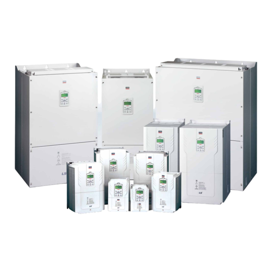
- Page 1 H100 Fan and Pump Drive 3-phase 200~240V 0.75~18.5kW 3-phase 380~480V 0.75~500kW...
- Page 2 The LS H100 drive solution is here for you. The LSLV-H100 sets the standard for the drive industry. Environmentally friendly water treatment and Fan and Pump systems incorporate the outstanding energy-saving benefits of the LSLV-H100 for fans and pumps. _ LS ELECTRIC...
-
Page 3: Table Of Contents
Fan and Pump Drive •Communication Module Exclusive Maximized User for Fan and Pump-BACnet •Global Specifications Convenience Compliant-UL Plenum Rated •Side-by-Side Installation Efficient Use of Space •Reduced Size •Soft Fill Control •Multiple-motor Control Stable System Control •Fire Mode Scan the QR code on your drive front and check the key use information ! Contents H100 _... -
Page 4: Maximized User Convenience
•400V 37~55kW Built-in option can be selected (C3) ※ 75~90kW satisfies EMC specifications even without a filter. Global Specifications Compliant UL Plenum Rated (American standards for conditioner fire safety) ※ Suitable for compartment for air handling/air conditioning _ LS ELECTRIC... - Page 5 Energy Saving Drive Communication Module •RS-485 capability is built-in: Modbus-RTU, Metasys N2 •BACnet MS/TP is embedded as standard •LonWorks option can be added Easy to Change Cooling Fan It is easy to change a cooling fan without opening the cover of a drive. DC Reactor A built-in DC Reactor effective to improve power factor and reduce THD is installed.
- Page 6 Parameter 2 Grp. WRITE Memory Memory Parameter 3 Grp. Part Download ………… ………… Smart copier receives from Smart copier sends to Drive Drive input/output part READ input/output part Smart copier receives from Drive input/output part READ _ LS ELECTRIC...
-
Page 7: Side-By-Side Installation
Energy Saving Drive Efficient Use of Space LSLV-H100 drives are miniaturized to reduce the space for installation, allowing the effective configuration of environment inside and outside a control panel. Reduced Size Main components are optimally deployed through thermal radiation analysis and 3D design to reduce size by compared to iP5A (Volume based). - Page 8 Dec Valve Ramp Frequency Prevents pump and pipe damages caused by sudden Dec Valve Freq pressure changes when pumps are stopped or a pump valve is Freq Limit Low Dec Valve Time closed, deceleration time can be set. Time _ LS ELECTRIC...
- Page 9 Energy Saving Drive Multi Motor Control MMC is used when a single drive is A u x used to control multiple motors M o t o r 1 00:00 A u x Pre-Heat in pump systems. M o t 02:00 o r 2 A u x It can control 1 main motor and...
-
Page 10: Fire Mode
Power-on Resume’is used to follow the previous control command. Sleep, Sleep Boost, Wake-up It is used to put the drive on standby and restarts it using PID in order to reduce motor loss as much as possible. _ LS ELECTRIC... - Page 11 Energy Saving Drive Auto Torque Boost The drive outputs voltage for the drive by controlling the level of boost to fit the load by itself. Lubrication Control When a control command is made in the Flow/Oiling Systems, lubrication signals are output for a certain period before the motors are started. Drive control is immediately started from the signal output point until the signals are turned off after the set time.
- Page 12 UL Type Reactor 0055-5.5kW 0370-37kW 1600-160kW 5000-500kW 0075-7.5kW 0450-45kW 1850-185kW 2 : 3-phase 200~240V O: UL Open D: Built in DC Reactor 0110-11kW 0550-55kW 2200-220kW 4 : 3-phase 380~480V E : UL Type1 N: Non DC Reactor _ LS ELECTRIC...
- Page 13 Input & Output Specification Energy Saving Energy Saving Drive 3-Phase 200V (0.75~18.5kW) Model Name LSLV□□□□H100-2□□□□ 0008 0015 0022 0037 0055 0075 0110 0150 0185 Applied Motor 0.75 18.5 Rated Capacity (kVA) 11.4 16.0 21.3 26.3 Rated Current Output Rating Output Frequency 0~400Hz Output Voltage (V) 3-Phase 200~240V...
- Page 14 Maximum 1000m above sea level for standard operation. Altitude From 1000 to 4000m, the rated input voltage and rated output current of the drive must be derated by 1% for every 100m. Vibration 9.8m/sec2(1.0G) or below Ambient atmospheric pressure 70~106kPa _ LS ELECTRIC...
- Page 15 Wiring Energy Saving Drive ※The default value is displayed in blue color H100 _...
- Page 16 Mains supply AC power connections. P2(+) / N(-) DC link terminal DC voltage terminals. P3(+) / N(-) Brake unit terminal Brake unit wiring connection. U / V / W Motor output terminal 3-phase induction motor wiring connections. _ LS ELECTRIC...
- Page 17 Energy Saving Drive Power Terminal Marks & Details 110~250kW (3-Phase) Terminal Mark Name Description R(L1) / S(L2) / T(L3) AC power input terminal Mains supply AC power connections. It can not be used. DC link terminal Connect to DC voltage terminal. P(+) / N(-) (or Brake unit terminal) (or Brake unit wiring connection)
- Page 18 V2 can be used by selecting analog voltage/current input Frequency Setting terminal setting switch (SW4). •nput current: 0~20mA (Current/Voltage) Terminal •Max. input current: 24mA •Input resistance 249Ω Frequency Setting (Pulse Train) Frequency is set as 0~32kHz. Terminal Low Level : 0~0.8V, High Level : 3.5~12V _ LS ELECTRIC...
- Page 19 Energy Saving Drive Output/Communication Terminal Marks & Details Classification Terminal Mark Name Description One of the following is chosen and output: Output frequency, output current, output voltage and DC voltage. The following voltage/current output can be chosen by selecting analog voltage/current Analog Output Voltage/Current Output Terminal output terminal setting switch (SW5).
- Page 20 3/0×4, 600×2 3/0×4, 600×2 70×4, 150×2 3/0×4 120×4, 300×2 120×4, 300×2 4/0×4, 600×2 4/0×4, 600×2 95×4, 200×2 4/0×4 120×4, 400×2 120×4, 400×2 4/0×4, 700×2 4/0×4, 700×2 120×4, 250×2 4/0×4, 750×2 185×4, 630×2 185×4, 630×2 350×4, 1500×2 350×4, 1500×2 _ LS ELECTRIC...
- Page 21 Energy Saving Drive Input/Output Terminal Screw Specifications Terminal Screw Torque Terminal Screw Torque Product (kW) Product (kW) Screw Size (Kgf.cm/Nm) Screw Size (Kgf.cm/Nm) 0.75 18.5 24.5~31.8/2.4~3.1 7.1~12.2/0.7~1.2 3-Phase 200V Class 61.2~91.8/6~9 24.5~31.8/2.4~3.1 3-Phase 18.5 400V Class 89.7~122.0/8.8~11.96 Terminal Screw Torque Product (kW) Screw Size (Kgf.cm/Nm)
- Page 22 O: Possible to write during operation Δ: Possible to write during stop X: Ban on writing 10(V3)~11(I3)’ of DRV-07 are available when Extension IO option is equipped. Refer to Extension IO option manual for more detail information. _ LS ELECTRIC...
- Page 23 Energy Saving Drive Code Comm. No. Name LCD Display Set Range Default Attribute 185.0 kW(300.0HP) 220.0 kW(350.0HP) 250.0 kW(400.0HP) Δ 0h110E Motor capacity Motor Capacity 315.0 kW(500.0HP) Depen dent on motor setting 355.0 kW(550.0HP) 400.0 kW(650.0HP) 500.0 kW(800.0HP) Manual Δ 0h110F Torque boosting Torque Boost...
- Page 24 ‘12(V3)~13(I3)’ of BAS-01 are available when Extension IO option is equipped. Refer to Extension IO option manual for more detail information BAS-02~BAS-03 code appears when BAS-01 code is not 0(None). ‘10(V3)~11(I3)’ of BAS-05 are available when Extension IO option is equipped. Refer to Extension IO option manual for more detail information. _ LS ELECTRIC...
- Page 25 Energy Saving Drive Comm. Code Name LCD Display Set Range Default Attribute 170~264V 0.75~18.5kW 220V 0h1213 Input power voltage AC Input Volt 320~528V 0.75~90kW 380V 320~550V 110~500kW None Δ All(rotation type) Automatic tuning Auto Tuning 0: None ALL(static type) Rs+Lsigma(rotation type) Δ...
- Page 26 ADV-14 code appears when ADV-08 code is set as 1(DC-Brake). ADV-28~ADV-33 codes appears when ADV-27 code is set as 1(Yes). ADV-51 is displayed when ADV-50 is set to ‘1 (Manual)’. ADV-52 is displayed when ADV-50 is set to ‘2 (Auto)’ _ LS ELECTRIC...
- Page 27 Energy Saving Drive Code Comm. No. Name LCD Display Set Range Default Attribute Δ 0h133C Acc/Dec. time switching frequency Xcel Change Fr 0.00~Max. frequency(Hz) 0.00 During Run 0h1340 Cooling fan control Fan Control Always ON 0: During Run Temp Control 0h1341 Saving up/down run frequency U/D Save Mode...
- Page 28 CON-72 code appears when Flying Start-1is set and when any one bit of CON-71 code is set as 1. CON-73~CON-75 codes appear when any one bit of CON-71 code is set as 1. CON-78~CON-83 codes appear when CON-77 code is set as 1(Yes) _ LS ELECTRIC...
- Page 29 Input Terminal Group (IN) Energy Saving Drive Code Comm. No Name LCD Display Set Range Default Attribute Jump code Jump Code 1~99 0h1501 Frequency upon maximuminput by analog Freq at 100% Start frequency ~ Max. frequency (Hz) Max. frequency 0h1505 V1 Input level display V1 Monitor(V) 0~12.00(V) or -12.00~12.00(V)
- Page 30 0h1562 TI quantizing level TI Quantizing 0.00 ,0.04~10.00(%) 0.04 53(Interlock6)~55(Interlock8)’ of IN-65~71 are available when Extension IO option is equipped. Refer to Extension IO option manual for more detail information Quantizing is disabled if ‘0’ is selected. _ LS ELECTRIC...
- Page 31 Energy Saving Drive Code Comm. No Name LCD Display Set Range Default Attribute Jump code JumpCode 1~99 Frequency Output Current Output Voltage DCLink Voltage Output Power Target Freq Ramp Freq PID Ref Value 0h1601 Analog output 1 item AO1 Mode PID Fdb Value 0: Frequency PID Output...
- Page 32 Pulse output gain TO Gain -1000.0~1000.0(%) 100.0 0h163F Pulse output bias TO Bias -100.0~100.0(%) 0h1640 Pulse output filter TO Filter 0-10000(msec) 0h1641 Pulse output constant output 2 TO Const % 0.0~100.0(%) 0h1642 Pulse output monitor TO Monitor 0.0~1000.0(%) _ LS ELECTRIC...
- Page 33 Communication Function Group (COM) Energy Saving Drive Code Comm. No Name LCD Display Set Range Default Attribute Jump code Jump Code 1~99 0h1701 Built-in communication drive ID Int485 St ID 1~250 ModBus RTU LS Inv 485 0h1702 Built-in communication protocol Int485 Proto 0: ModBus RTU BACnet RTU...
- Page 34 Virt DI Status Δ 0h173C Communica tion operation auto resume PowerOn Resume 0 : No ‘53 (Interlock6)~55(Interlock8)’ of COM-70~77 are available when Extension IO option is equipped. Refer to Extension IO option manual for more detail information. _ LS ELECTRIC...
- Page 35 Application Function Group (PID) Energy Saving Drive Code Comm. No Name LCD Display Set Range Default Attribute Jump code Jump Code 1~99 Δ 0h1801 PID function selection PID Sel 0: No 0h1802 E-PID selection E-PID Sel 0: No 0h1803 PID output monitor PID Output 0h1804 PID reference monitor...
- Page 36 ‘10(V3)~11(I3)’ of PID-20 are available when Extension IO option is equipped. Refer to Extension IO option manual for more detail information. '12(V3)~13(I3)’ of PID-21 are available when Extension IO option is equipped. Refer to Extension IO option manual for more detail information. _ LS ELECTRIC...
- Page 37 Energy Saving Drive Code Comm. No Name LCD Display Set Range Default Attribute 0h1817 PID feedback auxiliary gain PID Fdb Aux G -200.0~200.0(%) 0h1818 PID feedback band PID Fdb Band 0~Unit Band 0.00 0h1819 PID controller P-Gain 1 PID P-Gain 1 0.00~300.00(%) 50.00 0h181A...
- Page 38 PID Unit 0% -300.00~Unit Max accordingto PID50setting X0.1 -30.000~Unit Max X0.01 -3.0000~Unit Max X100 Unit Min~30000 Unit Min~3000.0 Rangevaries 0h1835 PID control 100% set value PID Unit 100% Unit Min~300.00 accordingto PID50setting X0.1 Unit Min~30.000 X0.01 Unit Min~3.0000 _ LS ELECTRIC...
- Page 39 EPID Function Group (EPID) Energy Saving Drive Code Comm. No Name LCD Display Set Range Default Attribute Jump code Jump Code 1~99 None Always ON 0h1901 EPID1 Mode selection EPID1 Mode 0: None During Run DI dependent 0h1902 EPID1 output monitor value EPID1 Output -100.00~100.00% 0.00...
- Page 40 ‘9(V3)~10(I3)’ of EPID-36 are available when Extension IO option is equipped. Refer to Extension IO option manual for more detail information. ‘8(V3)~9(I3)’ of EPID-38 are available when Extension IO option is equipped. Refer to Extension IO option manual for more detail information _ LS ELECTRIC...
- Page 41 Application Function Group Energy Saving Drive Application 1 Function Group Code Comm. No. Name LCD Display Set Range Default Attribute* Jump code Jump Code 1~99 0h1A05 Sleep boost level Sleep Bst Set 0.00~Unit Max 0.00 0h1A06 Sleep boost speed Sleep Bst Freq 0.00, Low Freq~High Freq 60.00 0h1A07...
- Page 42 PC Num of Steps 1~10 reverse steps during pump cleaning 0h1B1D Pump clean cycle monitoring Repeat Num Mon 0h1B1E Number of repeated pump cleaning Repeat Num Set 0~10 Set the operation mode to AUTO to configure AP2-01 _ LS ELECTRIC...
- Page 43 Energy Saving Drive Application 2 Function Group Code Comm. No. Name LCD Display Set Range Default Attribute* Stop 0h1B1F Operation after pump clean completion PC End Mode 0.Stop Δ 0h1B20 Continuous Pump Clean limit time PC Limit Time 6~60(min) 0h1B21 Continuous Pump Clean limit number PC Limit Num 0~10...
- Page 44 Except8 Date start time setting Except8 Start T 00:00~24:00(Min) 24:00 0h1C34 Except8 Date stop time setting Except8 Stop T Except8 StartT~24:00(Min) 24:00 0h1C35 Except8 Date setting Except8 Date 01/01~12/31(Date) 01/01 The date format can be changed according to the AP3-06 settings. _ LS ELECTRIC...
- Page 45 Energy Saving Drive Code Comm. No. Name LCD Display Set Range Default Attribute* 0h1C46 Time Event function setting Time Event En 0 : NO Δ 0h1C47 Time Event setting status T-Event Status 0h1C48 Time Event 1 connection setting T-Event1Period 000000000000~111111111111 000000000000 Δ...
- Page 46 Thermal In 0h1D23 Overheat motor sensor input selection Thermal In Src 0: Thermal In 0h1D24 Overheat motor sensor failure level Thermal-T Lev 0.0~100.0(%) 50.0 PRT-13~PRT-15 codes appear when PRT-12 code is not set as 0: None. _ LS ELECTRIC...
- Page 47 Energy Saving Drive Code Comm. No. Name LCD Display Set Range Default ribute* 0h1D25 Overheat motor sensor failure area Thermal-T 0: Low High 0h1D26 Overheat motor detection sensor ThermalMonitor None 0h1D28 Overheat motor trip selection ETH Trip Sel Free-Run 0: None Self-cool 0h1D29 Motor cooling fan type...
- Page 48 10.0 Δ 0h1D5F Delay of operating Broken belt Broken Belt Dly 0~600.0(sec) 10.0 Δ PRT-84 is displayed when PRT-83 is set to more than ‘0(%)’. PRT- 84 can only be set in Auto-State. PRT-86 is read only. _ LS ELECTRIC...
- Page 49 Motor 2 (2nd Motor) Function Group (M2) Energy Saving Drive Code Comm. No. Name LCD Display Set Range Default Attribute* Jump Code Jump Code 1~99 20.0 0.75~90kW 0h1E04 Acceleration time M2-Acc Time 60.0 110~250kW 100.0 315~500kW 30.0 0.75~90kW 0h1E05 Deceleration time M2-Dec Time 90.0 110~250kW...
- Page 50 Option slot 1 type Option-1 Type Option slot 2 type Option-2 Type Option slot 3 type Option-3 Type All Grp Parameter initialization Parameter Init DRV Grp 0: No BAS Grp ADV Grp For details,refer to option manual. _ LS ELECTRIC...
- Page 51 Energy Saving Drive Code Name LCD Display Set Range Default Reference CON Grp IN Grp OUT Grp COM Grp PID Grp Parameter initialization Parameter Init EPI Grp 0: No AP1 Grp AP2 Grp AP3 Grp PRT Grp M2 Grp View All Changed parameter display Changed Para 0: View All...
- Page 52 500.0 PID 3 PID Output M2 25 M2-V/F Patt 1: Square PID 4 PID Ref Value M2 28 M2-Stall Lev PID 5 PID Fdb Value M2 29 M2-ETH 1min PID 10 PID Ref 1 Src 4: I2 _ LS ELECTRIC...
- Page 53 Energy Saving Drive Exhaust Fan(MC3) Group Macro Code Code LCD Display Default Macro Code Code LCD Display Default Jump Code 1 : CODE PID 1 PID Sel 1: Yes 0.75~90kW 20.0 PID 3 PID Output DRV 3 Acc Time 110~250kW 60.0 PID 4 PID Ref Value...
- Page 54 ADV 65 U/D Save Mode 1: Yes M2 25 M2-V/F Patt 1: Square CON 4 Carrier Freq M2 28 M2-Stall Lev CON 70 SS Mode 0: Flying Start-1 M2 29 M2-ETH 1min CON 77 KEB Select 1: Yes _ LS ELECTRIC...
- Page 55 Energy Saving Drive Vacuum Pump (MC6) Group Macro Code Code LCD Display Default Macro Code Code LCD Display Default Jump Code 1 : CODE OUT 32 Relay 2 14: Run 0.75~90kW 30.0 PID 1 PID Sel 1 : Yes DRV 3 Acc Time 110~250kW 90.0...
- Page 56 5(0.20) 5(0.20) Unit: mm(inches) Product (Model) 3-Phase LSLV0150H100-2 180(7.09) 157(6.18) 290(44.42) 273.7(10.78) 11.3(0.45) 205.3(8.08) 5(0.20) 5(0.20) 200V LSLV0150H100-4 180(7.09) 157(6.18) 290(44.42) 273.7(10.78) 11.3(0.45) 205.3(8.08) 5(0.20) 5(0.20) 3-Phase 400V LSLV0185H100-4 180(7.09) 157(6.18) 290(44.42) 273.7(10.78) 11.3(0.45) 205.3(8.08) 5(0.20) 5(0.20) _ LS ELECTRIC...
- Page 57 Energy Saving Drive Unit: mm(inches) Product (Model) 3-Phase LSLV0185H100-2 220(8.66) 193.8(7.63) 350(13.78) 331(13.03) 13(0.51) 223.2(8.79) 6(0.24) 6(0.24) 200V LSLV0220H100-4 220(8.66) 193.8(7.63) 350(13.78) 331(13.03) 13(0.51) 223.2(8.79) 6(0.24) 6(0.24) 3-Phase 400V LSLV0300H100-4 220(8.66) 193.8(7.63) 350(13.78) 331(13.03) 13(0.51) 223.2(8.79) 6(0.24) 6(0.24) Unit: mm(inches) Product (Model) 3-Phase LSLV0370H100-4...
- Page 58 972(38.27) 15(0.59) 500(19.69) 14(0.55) 14(0.55) 185.5 3-Phase 400V LSLV3550H100-4 600(23.62) 420(16.54) 1000(39.37) 972(38.27) 15(0.59) 500(19.69) 14(0.55) 14(0.55) 185.5 LSLV4000H100-4 600(23.62) 420(16.54) 1000(39.37) 972(38.27) 15(0.59) 500(19.69) 14(0.55) 14(0.55) 185.5 LSLV5000H100-4 776(30.55) 500(19.69) 1054(41.50) 1021(40.20) 20(0.79) 500(19.69) 14(0.55) 14(0.55) _ LS ELECTRIC...
- Page 59 Energy Saving Drive Flange Drive + Flange Panel Cutting Ø5 Flange Unit: mm(inches) Product (Model) LSLV0008H100-2 206(8.11) 264.5(10.41) 181(7.13) 55.1(2.17) 186(7.32) 178(7.01) 251.5(9.90) 235(9.25) 8.4(0.33) LSLV0015H100-2 206(8.11) 264.5(10.41) 181(7.13) 55.1(2.17) 186(7.32) 178(7.01) 251.5(9.90) 235(9.25) 8.4(0.33) LSLV0022H100-2 206(8.11) 264.5(10.41) 181(7.13) 55.1(2.17) 186(7.32) 178(7.01) 251.5(9.90)
- Page 60 Unit: mm(inches) Product (Model) 3-Phase LSLV0150H100-2 225.2(8.87) 322.7(12.70) 205.3(8.08) 72.1(2.84) 205.2(8.08) 197.5(7.78) 309.7(12.19) 292.5(11.52) 9.3(0.34) 200V LSLV0150H100-4 225.2(8.87) 322.7(12.70) 205.3(8.08) 72.1(2.84) 205.2(8.08) 197.5(7.78) 309.7(12.19) 292.5(11.52) 9.3(0.34) 3-Phase 400V LSLV0185H100-4 225.2(8.87) 322.7(12.70) 205.3(8.08) 72.1(2.84) 205.2(8.08) 197.5(7.78) 309.7(12.19) 292.5(11.52) 9.3(0.34) _ LS ELECTRIC...
- Page 61 Energy Saving Drive Drive + Flange Panel Cutting Ø6 Flange Unit: mm(inches) Product (Model) 3-Phase LSLV0185H100-2 267(10.51) 384.5(15.14) 223.2(8.79) 93.6(3.69) 247(9.72) 239(9.41) 371.5(14.63) 352(13.86) 9.5(0.37) 200V LSLV0220H100-4 267(10.51) 384.5(15.14) 223.2(8.79) 93.6(3.69) 247(9.72) 239(9.41) 371.5(14.63) 352(13.86) 9.5(0.37) 3-Phase 400V LSLV0300H100-4 267(10.51) 384.5(15.14) 223.2(8.79) 93.6(3.69) 247(9.72) 239(9.41) 371.5(14.63) 352(13.86) 9.5(0.37)
- Page 62 H100 Dimensions Fan and Pump Flange 4-Ø7 Drive + Flange Flange Unit: mm(inches) Product (Model) 3-Phase 478.5 35.5 LSLV0370H100-4 26.4 400V (10.83) (9.13) (19.49) (18.84) (0.30) (11.18) (3.94) (2.17) (0.98) (1.40) (0.98) _ LS ELECTRIC...
- Page 63 Energy Saving Drive 4-Ø7 Drive + Flange Flange Unit: mm(inches) Product (Model) 555.5 57.5 35.5 LSLV0450H100-4 35.4 (12.80) (11.10) (21.87) (21.22) (0.30) (11.18) (3.94) (2.26) (0.94) (1.40) (0.94) 3-Phase 400V 555.5 57.5 35.5 LSLV0550H100-4 35.4 (12.80) (11.10) (21.87) (21.22) (0.30) (11.18) (3.94) (2.26)
- Page 64 Unit: mm(inches) Product (Model) 605.5 68.5 46.5 LSLV0750H100-4 43.5 (12.80) (10.83) (23.84) (23.11) (0.37) (12.17) (5.12) (2.69) (0.94) (1.83) (0.94) 3-Phase 400V 605.5 68.5 46.5 LSLV0900H100-4 43.5 (12.80) (10.83) (23.84) (23.11) (0.37) (12.17) (5.12) (2.69) (0.94) (1.83) (0.94) _ LS ELECTRIC...
- Page 65 Energy Saving Drive Conduit Drive + Conduit A1 A2 3-Ø22.3 3-Ø28.6 Conduit *Without rubber packing Unit: mm(inches) Product (Model) LSLV0008H100-2 160(6.30) 267.8(10.54) 232(9.13) 55.6(2.19) 181(7.13) 56.7(2.23) 52.5(2.07) 44(1.73) 21.5(0.85) 117. 6 (4. 6 3) 78(3.07) 43.5(1.71) 78(3.07) 32.5(1.28) LSLV0015H100-2 160(6.30) 267.8(10.54) 232(9.13) 55.6(2.19) 181(7.13) 56.7(2.23) 52.5(2.07) 44(1.73) 21.5(0.85) 117. 6 (4. 6 3) 78(3.07) 43.5(1.71) 78(3.07) 32.5(1.28) LSLV0022H100-2 160(6.30) 267.8(10.54) 232(9.13) 55.6(2.19) 181(7.13) 56.7(2.23) 52.5(2.07) 44(1.73) 21.5(0.85) 117.
- Page 66 (7.09) (2.19) (2.15) (0.10) (7.09) (12.83) (11.42) 3-Phase 400V 205.3 73.7 56.5 24.5 125.9 45.7 55.5 54.5 325.8 LSLV0185H100-4 (2.36) (8.08) (2.90) (2.22) (1.73) (0.96) (4.96) (3.54) (1.80) (3.54) (1.30) (7.09) (2.19) (2.15) (0.10) (7.09) (12.83) (11.42) _ LS ELECTRIC...
- Page 67 Energy Saving Drive Drive + Conduit A3 A2 3-Ø22.3 3-Ø44.5 Conduit *Without rubber packing Unit: mm(inches) Product (Model) 223.2 96.4 3-Phase 382.5 LSLV0185H100-2 (2.52) (8.79) (3.80) (2.09) (1.73) (0.83) (4.72) (3.46) (1.69) (3.31) (1.34) (8.46) (5.20) 200V (8.66) (15.06) (13.78) 223.2 96.4 382.5...
- Page 68 Fan and Pump Conduit Drive + Conduit 2-Ø22.3 3-Ø44.5 Conduit *Without rubber packing Unit: mm(inches) Product (Model) 3-Phase 521.5 112.5 105.8 LSLV0370H100-4 28.7 400V (10.83) (20.53) (17.72) (4.43) (11.18) (3.94) (6.38) (3.19) (7.24) (6.30) (4.17) (0.31) (10.83) _ LS ELECTRIC...
- Page 69 Energy Saving Drive Drive + Conduit 2-Ø22.3 3-Ø50.8 Conduit *Without rubber packing Unit: mm(inches) Product (Model) 600.5 105.8 LSLV0450H100-4 38.4 (12.80) (23.64) (20.08) (5.28) (11.18) (3.94) (6.38) (3.19) (7.24) (6.30) (4.17) (0.31) (12.80) 3-Phase 400V 600.5 105.8 LSLV0550H100-4 38.4 (12.80) (23.64) (20.08) (5.28)
- Page 70 Product (Model) 685.5 100.75 LSLV0750H100-4 47.2 (12.80) (26.99) (21.65) (7.20) (12.17) (5.12) (7.56) (3.19) (7.05) (6.10) (3.97) (0.31) (12.80) 3-Phase 400V 685.5 100.75 LSLV0900H100-4 47.2 (12.80) (26.99) (21.65) (7.20) (12.17) (5.12) (7.56) (3.19) (7.05) (6.10) (3.97) (0.31) (12.80) _ LS ELECTRIC...
- Page 71 Energy Saving Drive Drive + Conduit Conduit 2-Ø22.5 6-Ø63.5 *Without rubber packing Unit: mm(inches) Product (Model) 958.5 279.5 172.25 134.75 49.75 LSLV1100H100-4 62.31 (11.81) (37.74) (27.80) (11.00) (15.20) (6.81) (14.53) (7.09) (3.54) (7.72) (6.78) (5.31) (1.96) 3-Phase 400V 958.5 279.5 172.25 134.75 49.75...
- Page 72 *Without rubber packing Unit: mm(inches) Product (Model) LSLV1600H100-4 81.24 (14.96) (38.78) (27.76) (12.13) (15.59) (6.61) (15.00) (8.66) (4.17) (8.39) (7.32) (5.83) (2.28) 3-Phase 400V LSLV1850H100-4 81.24 (14.96) (38.78) (27.76) (12.13) (15.59) (6.61) (15.00) (8.66) (4.17) (8.39) (7.32) (5.83) (2.28) _ LS ELECTRIC...
- Page 73 Energy Saving Drive Drive + Conduit A1 A2 2-Ø22.5 Conduit 6-Ø92.5 *Without rubber packing Unit: mm(inches) Product (Model) 1360.3 922.3 LSLV2200H100-4 (16.77) (53.56) (36.31) (36.22) (18.98) (17.32) (7.83) (9.49) (7.05) (4.41) 3-Phase 400V 1360.3 922.3 LSLV2500H100-4 (16.77) (53.56) (36.31) (36.22) (18.98) (17.32) (7.83)
- Page 74 (14.96) 205.72 LSLV3550H100-4 (39.37) (22.54) (22.83) (9.96) (12.87) (8.27) (1.57) (9.25) (4.13) (7.48) 400V (23.62) (61.10) (39.45) 1000 572.5 1552 1002 205.72 LSLV4000H100-4 (39.37) (22.54) (22.83) (9.96) (12.87) (8.27) (1.57) (9.25) (4.13) (7.48) (14.96) (23.62) (61.10) (39.45) _ LS ELECTRIC...
- Page 75 Energy Saving Drive Drive + Conduit Conduit 2-Ø22.5 6-Ø135 *Without rubber packing Unit: mm(inches) Product (Model) 1054 592.4 618.5 251.5 247.5 3-Phase 1606 1059.5 (22.44) 290.91 LSLV5000H100-4 (41.50) (23.32) (24.35) (9.90) (14.45) (7.48) (9.74) (3.15) (10.63) (3.94) (9.84) (7.48) 400V (30.55) (63.23) (41.71)
- Page 76 5.05 1.56 3.56 1.16 2.53 0.76 1.64 0.61 1.42 18.5 0.48 0.98 0.40 0.88 0.29 0.59 0.29 0.24 3-Phase 400V 0.20 0.15 0.13 0.08 0.07 Built In 0.06 0.05 0.05 0.04 1000 0.03 1100 0.03 1250 0.03 _ LS ELECTRIC...
- Page 77 Energy Saving Drive Peripheral Devices Circuit Breaker(MCCB) Leakage Breaker(ELCB) Magnetic Contactor(MC) Capacity Voltage (kW) Model Rated Current(A) Model Rated Current(A) Model Rated Current(A) Model Rated Current(A) 0.75 MC-9a MC-18a ABS33c UTE100 EBS33c MC-32a MC-32a 3-Phase 200V ABS53c UTE100 EBS53c MC-50a ABS63c UTE100 EBS63c...
- Page 78 N(-) B1 Terminal for connection with B1 of DBU P(+) N(-) Terminal for connection with B2 of DBU Unused Dynamic Braking Unit B1 B2 Dynamic Braking Resistor P1(+) P2(+) N(-) R(L1) Motor Inout Power _ LS ELECTRIC S(L2) 50/60 Hz T(L3)
- Page 79 Energy Saving Drive Dynamic Braking Resistors Specification Torque 100% Torque 150% Wattage Wattage Wattage Wattage Product (kW) Resistor Resistor (Ω) (Ω) (%ED=5%) (%ED=10%) (%ED=5%) (%ED=10%) 0.75 1000 1200 3-Phase 200V 1200 1600 1600 1200 2400 1200 2400 2400 4800 2400 4800 2400 4800...
- Page 80 Dynamic Braking Unit Dynamic Braking Resistor R(L1) S(L2) Input power 110~500kW Motor H100 50/60 Hz T(L3) Bornes de la DBU Description B1, B2 Wire correctly referring to wiring diagram. DB Resistors connect with B1, B2 of DB Unit. _ LS ELECTRIC...
- Page 81 Memo Energy Saving Drive H100 _...
- Page 82 H100 Memo Fan and Pump _ LS ELECTRIC...
- Page 83 Memo Energy Saving Drive H100 _...
- Page 84 • LS ELECTRIC America Inc. (Chicago, USA) • LS ELECTRIC America Western Office (Irvine, USA) Tel: 1-800-891-2941 Fax: 1-847-383-6543 E-Mail: sales.us@lselectric.com Tel: 1-949-333-3140 E-Mail: jwyun@lselectric.biz ⓒ 2017. 08 LS ELECTRIC Co.,Ltd. All rights reserved. / (17) 2020. 04 Human Power 2020. 04...
Need help?
Do you have a question about the H100 Series and is the answer not in the manual?
Questions and answers