Sign In
Upload
Manuals
Brands
LS ELECTRIC Manuals
Control Unit
SV-iS7 Series
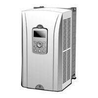
User Manuals: LS ELECTRIC SV-iS7 Series Low Voltage VFD
Manuals and User Guides for LS ELECTRIC SV-iS7 Series Low Voltage VFD. We have
8
LS ELECTRIC SV-iS7 Series Low Voltage VFD manuals available for free PDF download: User Manual
LS ELECTRIC SV-iS7 Series User Manual (491 pages)
AC Variable Speed Drive 0.75-75kW[200V] 0.75-375kW[400V]
Brand:
LS ELECTRIC
| Category:
DC Drives
| Size: 20 MB
Table of Contents
Table of Contents
7
About the Product
18
Preparing for Installation and Operation
18
Identifying the Product
18
Checking the Product for Defects or Damage
20
Preparing the Product for Installation and Operation
20
Installing the Product
20
Connecting the Cables
20
Part Names
21
Interior and Exterior View (IP 21 Model Types Less than 22 Kw [200 V] / Less than 75 Kw [400 V])
21
Interior and Exterior View (IP 54 Model Types Less than 22 Kw [200/400 V])
22
Interior and Exterior View (Model Types 30 Kw and up [200 V] / 90 Kw and up [400 V])
23
Technical Specifications
24
Input and Output Specifications 200 V Class (0.75-22 Kw)
24
Input and Output Specifications 200 V Class (30-75 Kw)
25
Input and Output Specifications 400 V Class (0.75-22 Kw)
26
Input and Output Specifications 400 V Class (30-160 Kw)
27
Input and Output Specifications 400 V Class (185-375 Kw)
28
Product Specification Details
30
Control
30
Operation
30
Protection Function
32
Structure and Operating Environment Control
32
Installing the Inverter
34
Installation Considerations
34
Selecting and Preparing a Site for Installation
35
Exterior and Dimensions (UL Enclosed Type 1, IP21 Type)
39
Exterior and Dimensions (UL Enclosed Type 12, IP54 Type)
53
Frame Dimensions and Weight (UL Enclosed Type 1, IP 21 Type)
57
Frame Dimensions and Weight (UL Enclosed Type 12, IP54 Type)
59
Installation Procedures for UL Enclosed Type12 and IP54 Type Products
60
Disassembling the Keypad Cover and Keypad
60
Disassembling the IP54
61
Mounting the Inverter
62
Connecting the Power Cables
63
Reassembling the IP54 Front Cover and the Keypad
64
Connecting the Cables
66
Removing the Front Cover for Cable Connection
66
IP 21 Type Products
66
IP 54 Type Products
68
Kw, 400 V and 30-75 Kw, 200 V Products
69
Activating and Deactivating the Built-In EMC Filter
70
Up to 7.5 Kw Inverters
70
Kw Inverters
72
Precautions for Wiring the Inverter
74
Ground Connection
75
Terminal Wiring Diagram
76
Up to 7.5 Kw Inverters
76
Kw Inverters
76
Kw Inverters
77
Connecting Cables to the Power Terminal Block
78
22 Kw (200 V/400 V)
78
Kw (200 V/400 V)
79
Kw (400 V)
80
Kw (400 V)
81
Kw (200 V/400 V)
82
Specifications of the Power Terminal Block and Exterior Fuse
83
Cable Length between the Inverter and the Motor
84
Protective Measures for the Inverter and the Motor
85
Control Terminal Wiring for Is7 Inverters Rated for up to 22 Kw
86
NPN Mode (Sink)
87
PNP Mode (Source)
87
22 Kw (Basic I/O)
88
Control Terminal Wiring for Is7 Inverters Rated for 30 Kw or more
89
Terminal Inputs for Inverter Operation
90
Cable Specifications for Control Block Wiring
92
Control Terminal Wiring for Is7 Extension I/O (Optional)
93
Terminal Inputs for Inverter Operation
94
Cable Specifications for Control Block Wiring
95
Setting the Built-In Surge Filter
96
Activating or Deactivating the Surge Filter
97
Is7 30-75KW (400 V) Inverters
97
Is7 90-375 Kw (400V) Inverters
97
Post-Installation Checklist
99
Test Run
100
Entering Easy Start Mode
100
Setting the Basic Parameters in Easy Start Mode
101
Checking the Inverter Operation
102
Peripheral Devices
103
Wiring Switch, Electronic Contactor, and Reactor Specifications
104
Wiring Switch, Short Circuit Switch, and Electronic Contactor
104
Reactors
106
Dynamic Braking Unit (DBU) and Resistor
109
DB Unit Dimensions
113
Indicators on the DB Unit
119
DB Resistors
119
DB Resistor Dimensions
122
Keypad Extension Cable for Remote Control (Optional)
123
Using the Keypad
126
About the Keypad
126
Dimensions
126
Key Functions
127
Display Items
128
Display Item List
128
Menu Items
131
Parameter Mode
132
User & Macro Mode
133
Navigating Modes
134
Mode Navigation at the Factory Default
134
Mode Navigation with User/Macro Mode and Trip Mode
135
Navigating Modes and Parameters
137
Group Navigation in Parameter Mode
137
Group Shift in User & Macro Mode
139
Navigating through Codes (Function Items)
140
Code Navigation in Monitor Mode
140
Code Navigation (Function Items) in Other Modes and Groups
141
Code Navigation Using Jump Code
142
Setting Parameters
144
Parameter Settings in Monitor Mode
144
Parameter Settings in Other Modes and Groups
145
Monitoring Operating Status
146
Using Monitor Mode
146
Monitoring Items
147
Using the Status Display
148
Monitoring Faults
149
Faults During Inverter Operation
149
Multiple Faults at a Time During Inverter Operation
150
Saving and Monitoring the Fault Trip History
150
Initializing Parameters
152
Basic Functions
154
Setting Frequency References
154
Keypad as the Source (Keypad-1 Setting)
155
Keypad as the Source (Keypad-2 Setting)
155
V1 Terminal as the Source
155
Setting a Frequency Reference Using an I/O Expansion Module (Terminal V2/I2)
165
Setting a Frequency with Pulse Input (with an Optional Encoder Module)
167
Setting a Frequency Reference Via RS-485 Communication
169
Frequency Hold by Analog Input
170
Changing the Displayed Units (Hz↔Rpm)
171
Setting Multi-Step Frequency
171
Command Source Configuration
174
The Keypad as a Command Input Device
174
The Terminal Block as a Command Input Device (Fwd/Rev Run Commands)
175
The Terminal Block as a Command Input Device (Run and Rotation Direction Commands)
176
Communication as a Command Input Device
177
Local/Remote Mode Switching
177
Forward or Reverse Run Prevention
179
Power-On Run
180
Reset and Restart
181
Setting Acceleration and Deceleration Times
182
Acc/Dec Time Based on Maximum Frequency
182
Acc/Dec Time Based on Operation Frequency
184
Multi-Step Acc/Dec Time Configuration
185
Configuring Acc/Dec Time Switch Frequency
186
Acc/Dec Pattern Configuration
188
Stopping the Acc/Dec Operation
191
V/F (Voltage/Frequency) Control
192
Linear V/F Pattern Operation
192
Square Reduction V/F Pattern Operation
193
User V/F Pattern Operation
194
Torque Boost
196
Manual Torque Boost
196
Auto Torque Boost
197
Advanced Auto Torque Boost
197
Output Voltage Setting
199
Start Mode Setting
200
Acceleration Start
200
Start after DC Braking
200
Stop Mode Setting
201
Deceleration Stop
201
Stop after DC Braking
202
Free Run Stop
203
Power Braking
204
Frequency Limit
205
Frequency Limit Using Maximum Frequency and Start Frequency
205
Frequency Limit Using Upper and Lower Limit Frequency Values
205
Frequency Jump
208
Nd Operation Mode Setting
209
Multi-Function Input Terminal Control
211
Expanded I/O Control with an Optional I/O Expansion Module
212
Learning Advanced Features
213
Operating with Auxiliary References
213
Jog Operation
218
Jog Operation 1-Forward Jog Via Multi-Function Terminal
218
Jog Operation 2-Forward/Reverse Jog Via Multi-Function Terminal
219
Jog Operation Via Keypad Input
220
Up/Down Operation
221
3-Wire Operation
225
Safe Operation Mode
226
Dwell Operation
227
Slip Compensation Operation
229
PID Control
232
PID Basic Operation
232
Pre-PID Operation
239
PID Sleep Mode
240
PID Switching (PID Openloop)
241
Auto Tuning
241
V/F Operation Using Speed Sensor
246
Sensorless-1 Vector Control
247
Sensorless-2 Vector Control
249
Vector Control Mode Operation
254
Torque Control
259
Droop Control
261
Speed / Torque Control Switching
261
Kinetic Energy Buffering
262
Energy Saving Operation
265
Manual Energy Saving Operation
265
Automatic Energy Saving Operation
266
Speed Search Operation
267
Auto Restart Settings
270
Operational Noise Settings (Carrier Frequency Settings)
272
2Nd Motor Operation
275
Supply Power Transition
277
Cooling Fan Control
278
Input Power Frequency Settings
279
Input Power Voltage Settings
280
Read, Write, and Save Parameters
280
Parameter Initialization
281
Parameter Viewing and Lock Options
283
Parameter View Lock
283
Parameter Lock
284
Changed Parameter Display
285
User Group
285
Macro Selection
287
Easy Start
288
Config (CNF) Mode
289
Timer Settings
290
Auto Sequence Operation
291
Traverse Operation
295
Brake Control
296
Multi-Function Output On/Off Control
299
MMC Function
299
Basic MMC Operation
302
Auto Change Operation
304
Interlock Operation
306
Bypass Operation (Regular Bypass)
308
Press Regeneration Prevention (to Evade Control Operation in the Status of Regeneration During Press)
309
Anti-Hunting Regulator
310
Fire Mode
311
Dynamic Braking (DB) Resistor Operation Reference Voltage
313
Kw/Hp Unit Selection
314
Output Voltage Drop Prevention
314
Using Monitor Functions
316
Monitoring the Operating Status Via the Keypad
316
Selecting Monitor Mode Display
316
Displaying Output Power
318
Selecting Load Speed Display
319
Selecting Hz/Rpm Display
319
Selecting Status Display
320
Monitoring Output Frequency
320
Monitoring Fault Status Using Keypad
321
Monitoring Current Fault Status
321
Monitoring Fault Trip History
322
Analog Output
323
Voltage Output (0-10 V)
323
Current Output (4-20 Ma)
326
Voltage Output (-10-+10V) Using an I/O Expansion Module
329
Current Output (4-20 Ma/0-20 Ma) Using an I/O Expansion Module
330
Relay Output and Multi-Function Output Terminal Settings
331
Fault Trip Output Using Multi-Function Output Terminals and Relays
337
Output Terminal Delay Time and Terminal Types
338
Output Terminal Delay Time
338
Setting the Output Terminal Type
338
Operation Time Monitor
339
Setting the Keypad Language
340
Using Protection Features
341
Motor Protection
341
Electrothermal Motor Overheating Prevention (ETH)
341
Overload Early Warning and Trip
343
Stall Prevention and Flux Braking
344
Motor Overheat Sensor Input
348
Inverter and Sequence Protection
350
Open-Phase Protection
350
External Trip Signal
352
Inverter Overload Protection (IOLT)
352
Keypad Command Loss
353
Speed Command Loss
355
Dynamic Braking (DB) Resistor Configuration
357
Underload Warning and Failure
358
Overspeed Fault
360
Speed Deviation Fault
360
Speed Sensor (Encoder) Fault Detection
360
Fan Fault Detection
361
Low Voltage Fault Trip
361
Output Block Via the Multi-Function Terminal
362
Trip Status Reset
363
Operation Mode on Optional Expansion Module Fault Trip
363
No Motor Trip
364
Low Voltage Fault Trip 2 During Operation
364
List of Faults and Warnings
365
Communication Function
368
Introduction
368
Specifications
369
Communication System Configuration
370
Basic Settings
371
Setting Operation Command and Frequency
372
Command Loss Protection
372
Setting Virtual Multi-Function Inputs
373
Saving Parameters Defined by Communication
374
Communication Frame Monitoring
375
Special Communication Area Settings
375
Parameter Group for Periodical Data Transmission
376
U&M Mode
378
Communication Protocol
378
LS INV 485 Protocol
378
Modbus-RTU Protocol
384
Is7/Is5/Ig5/Ig5A Compatible Common Area Parameter
386
Expansion Common Area Parameter
390
Troubleshooting and Maintenance
404
Protection Functions
404
Protection from Output Current and Input Voltage
404
Abnormal Circuit Conditions and External Signals
405
Keypad and Optional Expansion Modules
407
Warning Messages
408
Troubleshooting Fault Trips
409
Replacing the Cooling Fan
412
Products Rated below 7.5 Kw
412
Products Rated at 11-15 Kw 200 V/400 V and 18.5-22 Kw 400 V
412
Products Rated at more than 30 Kw (200 V) / 90 Kw (400 V), and 18.5-22 Kw (200 V) / 30-75 Kw (200/400 V)
413
Daily and Regular Inspection Lists
414
Table of Functions
417
Parameter Mode - DRV Group (DRV)
417
Parameter Mode - Basic Function Group (BAS)
420
Parameter Mode - Expansion Function Group (PARADV)
424
Parameter Mode - Control Function Group (CON)
428
Parameter Mode - Input Terminal Block Function Group (IN)
434
Parameter Mode - Output Terminal Block Function Group (OUT)
438
Parameter Mode - Communication Function Group (COM)
442
Parameter Mode - Applied Function Group (APP)
445
Parameter Mode - Auto Sequence Operation Group (AUT)
448
Parameter Mode - Option Module Function Group (APO)
451
Parameter Mode - Protective Function Group (PRT)
454
Parameter Mode - 2Nd Motor Function Group (M2)
457
Trip Mode (TRP Current (or Last-X))
458
Config Mode (CNF)
458
User/Macro Mode - Draw Operation Function GroupMc1
462
User/Macro Mode - Traverse Operation Function Group (MC2)
463
Safety Funtion STO(Safe Torque Off)
464
Safety Standard Product
464
About the Safety Function
464
Safety Function Wiring Diagram
465
Installing the Safety Board to 0.75-160 Kw Product
466
Installing the Safety Board to 185-375 Kw Product
466
Safety Function Terminal Description
467
Cable Specification for Signal Terminal Block Wiring
467
Marine Certification
468
DNV (Det Norske Veritas) Marine Certification Details
468
Bureau Veritas (Marine & Offshore Division) Marine Certification Details
468
ABS Marine Certification Details
468
KR Marine Certification Details
469
Marine Certification Models for SV-Is7 Products
469
Using a Single Phase Power Source
471
Single Phase Rating
471
Power(Hp), Input Current and Output Current
472
Input Frequency and Voltage Tolerance
473
Wiring and Peripheral Device
474
Other Considerations
477
Storage and Disposal
478
Storage
478
Disposal
478
Product Warranty
482
Index
485
Advertisement
LS ELECTRIC SV-iS7 Series User Manual (300 pages)
Brand:
LS ELECTRIC
| Category:
Controller
| Size: 31 MB
LS ELECTRIC SV-iS7 Series User Manual (106 pages)
IS7 RAPIEnet+ Option Module
Brand:
LS ELECTRIC
| Category:
Control Unit
| Size: 4 MB
Table of Contents
Table of Contents
3
Overview
6
Rapienet+ Technical Specifications
6
Package Components
7
Device Type for the Is7 Rapienet+ Communication Board
7
Is7 Rapienet+ Communication Board Layout and Installation
7
External Layout
7
Installing the Is7 Rapienet+ Communication Board
8
Network Connection
9
Network Connection Cable Wiring
9
Communication Cable Connector
9
Network Cable Specifications
10
Frequency Band
10
Twisted Pair Cable Types
10
Inverter Communication Address
11
Keypad Parameters for Rapienet+ Communication Board
12
Description of Keypad Parameters Related to Rapienet+ Communication Board
15
Description of Keypad Parameters (Simplified)
15
CNF Group
17
DRV Group
17
COM Group
17
PRT Group (Lost Command)
21
Service When Connected with Our Products
22
Overview
22
Smart Scaling (LS ELECTRIC Master Module: XGL-Efmxb V8.0 or Later)
22
Configuring the XG5000 Program for the PLC
24
Configuring the Master Module
25
Network Device Settings
25
Input/Output Parameter Settings
26
Diagnostic Parameter Settings
26
Network Device Connections
27
Service Status
27
LED Indications and Troubleshooting
30
Services with LS ELECTRIC Products or Other Manufacturer's Products
32
Overview
32
Ethernet/Ip
32
Basic Protocol Structure
32
Implicit Message
33
Explicit Messages
39
Supported Objects
39
Modbus TCP Frame
47
Modbus TCP Frame Structure
47
Function Codes
48
Exception (Except) Frame
50
LED Indications and Troubleshooting
52
Rapienet+ Technical Features
58
제품 구성물
59
Is7 Rapienet+ 통신 옵션 보드 형명
59
Is7 Rapienet+ 통신 옵션 보드 외관 및 설치
59
Is7 Rapienet+ 통신 옵션 보드 설치
60
Network 연결
61
통신선 연결 단자 관련 정보
61
통신선 연결 단자 부
61
Network 케이블 규격
62
사용 주파수 대역
62
Twist Pair 선 종류
62
인버터 통신 주소
63
Rapienet+ 통신 옵션 보드와 관련 Keypad 파라미터
64
Rapienet+ 통신 옵션과 관련 Keypad 파라미터 설명
67
Keypad 파라미터 설명 간략본
67
Cnf 그룹
69
Drv 그룹
69
Com 그룹
69
PRT 그룹(Lost Command)
73
당사 제품과 연결 시 서비스
74
스마트 증설 (당사 마스터 XGL-Efmxb V8.0 이상)
74
Plc 의 Xg5000 프로그램, 설정 방법
76
마스터 설정
77
통신 디바이스 동작 설정
77
입력/출력 변수 할당
78
진단 변수 할당
78
통신 디바이스 연결 구성
79
서비스별 상태
79
Led 정보 및 고장 처리
82
당사 or 타사 제품과 연결 시 서비스
84
Ethernet/Ip
84
프로토콜에 대한 기본 구성
84
Implicit Message
85
Explicit Message
92
지원 Object
92
Modbus TCP Frame
100
Modbus TCP Frame 구성
100
Function Code 에 대한 설명
101
Except Frame
103
Led 정보 및 고장 처리
104
Advertisement
LS ELECTRIC SV-iS7 Series User Manual (61 pages)
Profibus
Brand:
LS ELECTRIC
| Category:
Inverter
| Size: 1 MB
Table of Contents
Table of Contents
4
Overview
6
Introduction
6
Package Content
6
Product Specification
7
Basic Communication Specifications for the Profibus Option
7
Appearance and Part Name
9
How to Fit Option
11
Mounting Option to the Inverter Body
11
Structure of Profibus Signal Line Connector and Connector Connection Method
12
Grounding Option
13
Profibus Parameters
15
Setting Station Address
15
Setting the Number of Status Data
15
Setting the Number of the Control Data
15
Setting Address for the Output Data
16
Setting Address for the Input Data
16
Transmitting and Receiving I/O Data
16
Setting Profibus Bit Swap
17
Profibus DP Telegram Type
17
Profibus DP Profile
18
Profibus DP Baudrate
18
Profibus DP Module Reset
19
Profibus DP Profidrive Value
19
Basic Operation
20
Abnormal Operation and Countermeasures
21
DATA_EX LED Operation and Countermeasures in Case of Malfunction
21
CPU LED Operation and Countermeasures in Case of Malfunction
22
Error LED Operation and Countermeasures in Case of Malfunction
22
System Configuration and Transmission Specification
23
Methods and Specifications for Installing Terminating Resistance
23
Maximum Transmission Distance Specification
24
Preferences and Other Features
25
GSD Files (Electronic Data Sheets)
25
User Parameter Setting
25
Extended Diagnostic
26
Communication Parameters
27
Map Structure of the Is7 Inverter Full Communication Parameters
27
Parameter Groups for Periodic Data Transmission
28
Parameter Groups for User and Macro Grp Transport
29
0H200 to 0H23F: User Grp Parameter Currently Registered
30
Product Size
31
Communication Profile
32
Profidrive Profile
33
Control Word(STW1)
35
Status Word(ZSW1)
36
Setpoint Value
37
Actual Speed Value
38
I/O Profile
38
LS Drive Profile
38
Control Word
39
Status Word
40
Setpoint Value
41
Actual Speed Value
41
Communication Protocol
42
Cyclical Message Types
42
PPO Type
42
Standard Telegram1
43
Vender Specific Telegram
44
Parameter Access
44
Cyclic Parameter Data Transfer (DP-V0)
44
Acyclic Parameter Data Transfer (DP-V1)
49
Profidrive Parameters
54
Supported Parameters
54
Description of the PNU[944] Fault Message Counter and the PNU[947] Fault Number
56
M Records
59
LS ELECTRIC SV-iS7 Series User Manual (84 pages)
Ethernet communication option module connects the iS7 inverter to the Ethernet network
Brand:
LS ELECTRIC
| Category:
Control Unit
| Size: 27 MB
LS ELECTRIC SV-iS7 Series User Manual (46 pages)
Brand:
LS ELECTRIC
| Category:
Recording Equipment
| Size: 2 MB
Table of Contents
Table of Contents
4
Introduction
5
Rapienet Technical Specifications
5
Included Items
5
Designation
5
Part Names and Installation
6
Network Connections
9
Network Cable Specification
10
Rapienet Communication Related Keypad Parameters
11
Rapienet Communication Options and Related Keypad Parameters
13
Inverter Communication Address
17
High-Speed Link
19
P2P Communication
20
Rapienet Technical Features
26
제품 구성물
26
Is7 Rapienet 통신 옵션 형명
26
Rapienet 통신 옵션 외관 및 설치
27
Network 연결
30
Network 케이블 규격
31
Rapienet 통신 옵션과 관련 Keypad 파라미터
32
Rapienet 통신 옵션과 관련 Keypad 파라미터 설명
34
인버터 통신 주소
40
고속링크 통신
41
P2P 통신
43
LS ELECTRIC SV-iS7 Series User Manual (39 pages)
iS7 Rnet/Fnet Option
Brand:
LS ELECTRIC
| Category:
Conference System
| Size: 1 MB
Table of Contents
Table of Contents
3
Introduction
4
Technical Date for Rnet/Fnet Communication Board
4
Rnet/Fnet Cable Connection
5
Product Contents
5
Rnet/Fnet Communication Board
6
Rnet/Fnet LED Information
7
Rnet/Fnet Related Keypad Parameter
8
Connection to LS ELECTRIC PLC with Rnet/Fnet
13
Rnet/Fnet 통신 카드 Technical Data
23
Rnet/Fnet 통신선 연결
24
제품 구성물
24
Rnet/Fnet 통신카드 내부 및 외관/설치
25
Rnet/Fnet LED 정보
26
Rnet/Fnet 관련 Keypad 파라미터
27
LS ELECTRIC PLC와 Rnet/Fnet 통신 연결하기
32
LS ELECTRIC SV-iS7 Series User Manual (27 pages)
NEMA4X/IP66 Keypad Mount Option
Brand:
LS ELECTRIC
| Category:
Keypad
| Size: 5 MB
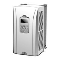
Table of Contents
Safety Instructions
4
Operating Precautions
6
Preface and Safety
7
Product Overview
8
Before Using the Product
8
Revision History
13
Product Warranty
14
Advertisement
Related Products
LS ELECTRIC SV-iV5 Series
LS ELECTRIC SV-iP5A Series
LS ELECTRIC Susol Series
LS ELECTRIC S100-1 Series
LS ELECTRIC S100-2 Series
LS ELECTRIC S100-4 Series
LS ELECTRIC LSLV0185 S100-4EOFNM
LS ELECTRIC LSLV0004 S100-1EOFNM
LS ELECTRIC S100
LS ELECTRIC Susol
LS ELECTRIC Categories
Controller
Control Unit
DC Drives
Servo Drives
Inverter
More LS ELECTRIC Manuals
Login
Sign In
OR
Sign in with Facebook
Sign in with Google
Upload manual
Upload from disk
Upload from URL