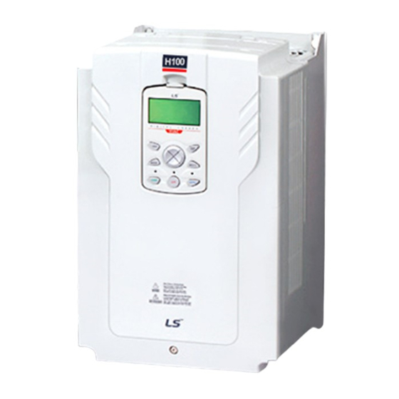
Summary of Contents for LS ELECTRIC H100 2(PLUS) Series
Page 1
This operation manual is intended for users with basic knowledge of electricity and electric devices. * LSLV-H100+ is the official name for the H100+ series inverters. * The H100+ series software may be updated without prior notice for better performance. To check the latest software, visit our website at http://www.ls-electric.com.
Page 2
Quick Start Reference Quick Start Reference This chapter provides details on product identification, part names, correct installation and cable specifications. To install the inverter correctly and safely, carefully read and follow the instructions. Verify & Identify the delivery Verify that you have ordered and received the correct VFD by checking the nameplate information. Utilize the example name plate below to assist you with this.
Page 3
Quick Start Reference After mounting, and in order to move onto the wiring step, loosen the captive screw on the terminal cover. Squeeze the tabs and “hinge off” the cover. Squeeze tabs and slide up the wire guide to expose the power terminals. This wire guide can be disposed of if you have purchased a NEMA 1 conduit kit.
Page 4
Quick Start Reference Wiring the VFD : Control The figures below show the control circuit terminal arrangement on the drive. Switch Description Terminating Resistor (Left: On, Right: Off) Left: PNP, Right: NPN Left: V1, Right: T1(PTC) analog input (Left: I2, Right: V2) analog output (Left: VO, Right: IO)
Page 5
Quick Start Reference Function Label Name Description P1: Fx (IN-65) P2: Rx (IN-66) P3: BX (IN-67) Multi-function P1–P7 Multi-function Input 1-7 P4: RST (IN-68) terminal P5: Speed-L (IN-69) configuration P6: Speed-M (IN-70) P7: Speed-H (IN-71) Common terminal Maximum Voltage Output: 12 V Potentiometer power supply Maximum Current Output: 12 mA Potentiometer : 1–10k Ω...
Page 6
Quick Start Reference Keypad: Description Name Description [MODE] Key Used to switch between modes. [PROG / ENT] Key Used to select, confirm, or save a parameter value. [Up] [Down] key Switch between codes or increase or decrease parameter values. Switch between groups or move the cursor during parameter setup [Left] [Right] key or modification.
Page 7
Quick Start Reference Keypad Navigation and Parameter Changes Navigate and select different parameters by using the directional arrows on the keypad while in the PAR Mode. From the main screen, the [MODE] key will change the keypad to display the Parameter (PAR) mode.
Page 8
Quick Start Reference Verify Motor Direction This step explains how to check motor direction by running the motor at a low speed via the keypad in HAND mode. Verify that the power and motor wiring matches the previous step and covers are installed before applying power.
Page 9
Quick Start Reference HAND / AUTO / OFF keys The H100+ series inverters have two operation modes–the HAND and AUTO modes. HAND mode is used for local control using the keypad. AUTO mode is used for remote control using the terminal inputs or networks commands (the keypad may still be used in AUTO mode if the command source is set as ‘keypad’).
Page 10
Quick Start Reference Codes / Functions Description DRV-01 Frequency reference in AUTO mode when DRV-07 is set to’ KeyPad’. Cmd Frequency DRV-02 Rotation direction of the keypad command in the HAND or AUTO mode. KeyPad Run Dir Settings Description Forward Fx operation Reverse Rx operation...
Page 11
Quick Start Reference Control Wiring This step shows common wiring examples for both the run command and frequency reference when operating in AUTO Mode. However, when DRV-08 Auto Mode Sel is set to “1. Disabled” (Factory default), it’s available to operate without trasffering to “AUTO Mode”. 2-Wire Control 2-wire control consists of maintained run signals.
Page 12
Quick Start Reference EZ Start This Step provides details on EZ start steps. Step Parameter Description 0. Basic (Default) CNF-43: Select a macro. 1. Pressure Ctrl 2. Lead-Lag 0. US DRV 32: Regional Set 1. International 2. KR AP3-01 Now Date Set Date AP3-02 Now Time Set Time...
Page 13
Quick Start Reference Step Parameter Description Select start at trip reset Setting Function Standard Trips √ except the below √ Low Voltage Trip Low Feedback PRT-08 Select start at trip √ Trip reset High Feedback √ Trip √ SetPoint Timeout √...
Page 14
Quick Start Reference Basic Setup The basic drive and motor parameters are shown on the below table. Set the parameters according to your specific application. 1. Motor Parameters Set the below motor parameters based on the motor nameplate. Group Description Default Set Options Motor Capacity...
Page 15
Quick Start Reference Application Setup This step shows how to set the pressure control. 1. Activate PID function ▶ PID-01 PID Sel To enable PID operation, set [PID-01 PID Sel] to “Yes” ▶ PID-02 PID Access Lev The Default Value for [PID-02 PID Access Lev] only allows access to the basic parameters in the PID group.
Page 16
Quick Start Reference 3. Setpoint, Feedback Scaling ▶ PID-10 PID Setpoint 1 Source Setting Keypad FieldBus Pulse Int485 ▶ PID-11 PID Setpoint 1 Set A setpoint value can be entered if the PID setpoint source (PID-10) is set to ‘0 (Keypad)’. And also PID setpoint can be set in Monitor screen when PID-10 is set to ‘0 (Keypad)’.
Page 17
Quick Start Reference 4. Wakeup level ▶ PID-57 WakeUpLev type 0. Absolute or 1. Deviation (Factory default) can be selected for the Wake-up level Setpoint Wakeup Delay time =Set poi nt-wakeup level Wakeup Level ▶ PID-64 PID WakeUp 0 DT ▶...
Page 18
Quick Start Reference 6. High/Low Feedback Detection Low/High feedback detection detects whether PID feedback is higher than high feedback level or lower than low feedback level to trigger Warning or Trip&Coast stop. ▶ AP2-48 High Feedback Detection Mode ▶ AP2-49 High Feedback Level Fault Delay Time ▶...
Page 19
Quick Start Reference 7. Thrust Bearing Control Thrurst Bearing Control function changes acceleration and deceleration time based on a certain frequency in order to protect the bearing of the submersible pump. ▶ AP2-40 Thrust Frequency ▶ AP2-41 Thrust Bearing Acceleration Time ▶...
Page 20
Quick Start Reference Macro – Pressure Control (MC1) Group Macro Macro Code Initial Value Code Initial Value Code Display Code Display 0.75~9 10.0 Jump DRV- 110~25 1: CODE Acc Time 30.0 Code 315~50 50.0 0.75~90 20.0 DRV- 110~25 DRV- 60.0 1: Fx/Rx-1 Time Source...
Page 21
Quick Start Reference 100% fAtRun PID- PID- Pump Min Acc/Dec 60.00 30.00 Speed PID- WakeUp PID- Sleep Lev 1. Output 1. Deviation Lev type Type Frequency PID- PID- Sleep 0 10.0 Sleep0Lev PID- PID- WakeUp 10.0 WakeUp0L 20.0 0 DT AP2- Thrust AP2-...
Page 22
Safety Information Safety Information Read and follow all safety instructions in this manual precisely to avoid unsafe operating conditions, property damage, personal injury, or death. Safety symbols in this manual Indicates an imminently hazardous situation which, if not avoided, will result in severe injury or death.
Page 23
Safety Information • Do not allow foreign objects, such as screws, metal chips, debris, water, or oil to get inside the inverter. Allowing foreign objects inside the inverter may cause the inverter to malfunction or result in a fire. • Do not operate the inverter with wet hands.
Table of Contents Table of Contents Preparing the Installation .................. 1 Product Identification ................. 1 Part Names ....................3 Installation Considerations ..............10 Selecting and Preparing a Site for Installation ........11 Cable Selection ..................14 Installing the Inverter ..................17 Mounting the Inverter ................
Page 25
Table of Contents Output Terminal Block Function Group (OUT) ........101 Communication Function Group (COM) ..........107 PID Function Group(PID) .............. 114 Application 1 Function Group (AP1) ............ 126 4.10 Application 2 Function Group (AP2) ..........134 4.11 Application 3 Function Group (AP3) ..........139 4.12 Application 4 Function Group (AP4) ..........
Preparing the Installation 1 Preparing the Installation This chapter provides details on product identification, part names, correct installation and cable specifications. To install the inverter correctly and safely, carefully read and follow the instructions. 1.1 Product Identification The H100+ Inverter is manufactured in a range of product groups based on drive capacity and power source specifications.
Page 28
Preparing the Installation Note The H100+ 75/90 kW, 400 V inverters satisfy the EMC standard EN61800-3 without installation of optional EMC filters.
Preparing the Installation 1.3 Installation Considerations Inverters are composed of various precision, electronic devices, and therefore the installation environment can significantly impact the lifespan and reliability of the product. The table below details the ideal operation and installation conditions for the inverter. Items Description -10 ℃–50 ℃...
Preparing the Installation 1.4 Selecting and Preparing a Site for Installation When selecting an installation location consider the following points: • The inverter must be installed on a wall that can support the inverter’s weight. • The location must be free from vibration. Vibration can adversely affect the operation of the inverter.
Page 38
Preparing the Installation • Ensure sufficient air circulation is provided around the inverter when it is installed. If the inverter is to be installed inside a panel, enclosure, or cabinet rack, carefully consider the position of the inverter’s cooling fan and the ventilation louver. The cooling fan must be positioned to efficiently transfer the heat generated by the operation of the inverter.
Page 39
Preparing the Installation Note • The vent covers must be removed for side-by-side installations. • Side-by-side installation cannot be used for the H100+ inverters rated for 37 kW and above. • For the H100+ inverters rated for 37 kW and above, if the installation site satisfies the UL Open Type requirements and there is no danger of foreign objects getting inside the inverter and causing trouble, the vent cover may be removed to improve cooling efficiency.
Preparing the Installation 1.5 Cable Selection When you install power and signal cables in the terminal blocks, only use cables that meet the required specification for the safe and reliable operation of the product. Refer to the following information to assist you with cable selection. •...
Installing the Inverter 2 Installing the Inverter This chapter describes the physical and electrical installation of the H100+ series inverters, including mounting and wiring of the product. Refer to the flowchart and basic configuration diagram provided below to understand the procedures and installation instructions to be followed to install the product correctly.
Page 44
Installing the Inverter Basic configuration diagram The reference diagram below shows a typical system configuration showing the inverter and peripheral devices. Prior to installing the inverter, ensure that the product is suitable for the application (power rating, capacity, etc). Ensure that all of the required peripherals and optional devices (resistor brakes, contactors, noise filters, etc.) are available.
Installing the Inverter • Figures in this manual are shown with covers or circuit breakers removed to show a more detailed view of the installation arrangements. Install covers and circuit breakers before operating the inverter. Operate the product according to the instructions in this manual. •...
Page 47
Installing the Inverter Install the two lower mounting bolts. Ensure that the inverter is placed flat on the mounting surface, and that the installation surface can securely support the weight of the inverter. 400[V] : 220~500kW • Do not transport the inverter by lifting with the inverter’s covers or plastic surfaces. The inverter may tip over if covers break, causing injuries or damage to the product.
Installing the Inverter 2.2 Enabling the RTC (Real-Time Clock) Battery The H100+ series inverter comes from the factory with a CR2032 lithium-manganese battery pre-installed on the I/O PCB. The battery powers the inverter’s built-in RTC. The battery is installed with a protective insulation strip to prevent battery discharge; remove this protective film before installing and using the inverter.
Page 50
Installing the Inverter 110~185kW Models 220~500kW Models Remove the keypad from the inverter body. 0.75–30 kW Models 37–90 kW Models...
Page 51
Installing the Inverter Loosen the screws securing the front cover, and remove the front cover by lifting it. The main PCB is exposed. 0.75–30 kW Models 37–90 kW Models Locate the RTC battery holder on the I/O PCB, and remove the protective insulation strip by gently pulling it.
Installing the Inverter 2.3 Cable Wiring Open the terminal cover, remove the cable guides, and then install the ground connection as specified. Complete the cable connections by connecting an appropriately rated cable to the terminals on the power and control terminal blocks. Read the following information carefully before carrying out wiring connections to the inverter.
Page 53
Installing the Inverter Step 1 Terminal Cover and Cable Guide The terminal cover and cable guide must be removed to install cables. Refer to the following procedures to remove the covers and cable guide. The steps to remove these parts may vary depending on the inverter model. Loosen the bolt that secures the terminal cover.
Page 54
Installing the Inverter Step 2 Ground Connection Remove the terminal cover(s) and cable guide. Then follow the instructions below to install the ground connection for the inverter. Locate the ground terminal and connect an appropriately rated ground cable to the terminals.
Page 55
Installing the Inverter 315~500kW (3-Phase) Connect the other ends of the ground cables to the supply earth (ground) terminal Note • 200 V products require Class 3 grounding. Resistance to ground must be ≤ 100 Ω. • 400 V products require Special Class 3 grounding. Resistance to ground must be ≤ 10 Ω. Install ground connections for the inverter and the motor by following the correct specifications to ensure safe and accurate operation.
Page 56
Installing the Inverter • Use copper wires only with 600 V, 75 ℃ rating for the power terminal wiring, and 300 V, 75 ℃ rating for the control terminal wiring. • Power supply wirings must be connected to the R, S, and T terminals. Connecting them to the U, V, W terminals causes internal damages to the inverter.
Page 57
Installing the Inverter 0.75–30 kW (3-Phase) Power Terminal Labels and Descriptions Terminal Labels Name Description R(L1) / S(L2) / T(L3) AC power input terminal Mains supply AC power connections. P2(+) / N(-) DC link terminal DC voltage terminals. DC Reactor wiring connection. (When you P1(+) / P2(+) DC Reactor terminal use the DC Reactor, must remove short-...
Page 58
Installing the Inverter 37–90 kW (3-Phase) Power Terminal Labels and Descriptions Terminal Labels Name Description R(L1) / S(L2) / T(L3) AC power input terminal Mains supply AC power connections. P2(+) / N(-) DC link terminal DC voltage terminals. P3(+) / N(-) Brake unit terminals Brake unit wiring connection.
Page 59
Installing the Inverter 110–250kW (3-Phase) Power Terminal Labels and Descriptions Terminal Labels Name Description R(L1) / S(L2) / T(L3) AC power input terminal Mains supply AC power connections. It can not be used because it does not provide a braking module DC link terminal DC voltage terminals.
Page 60
Installing the Inverter 315–500kW (3-Phase) Terminal Labels Name Description R(L1) / S(L2) / T(L3) AC power input terminal Mains supply AC power connections. DC link terminal DC voltage terminals. P(+) / N(-) (or Brake unit terminals) (or Brake unit wiring connection) 3-phase induction motor wiring U / V / W Motor output terminals...
Page 61
Installing the Inverter Note • Apply a DC input to the P2 (+) and N (-) terminals to operate the inverter on DC voltage input. • Use STP (Shielded Twisted Pair) cables to connect a remotely located motor with the inverter.
Page 62
Installing the Inverter Step 4 Control Terminal Wiring The illustrations below show the detailed layout of control wiring terminals and control board switches. Refer to the detailed information provided below and 1.5 Cable Selection on page 14 before installing control terminal wiring and ensure that the cables used meet the required specifications.
Page 63
Installing the Inverter Input and Output Control Terminal Block Wiring Diagram...
Page 64
Installing the Inverter Input Terminal Labels and Descriptions Function Label Name Description Configurable for multi-function input terminals. Factory default terminals and setup are as follows : P1: Fx P1– P2: Rx Multi-function Input 1-7 P3: BX Multi-function P4: RST terminal P5: Speed-L configuration P6: Speed-M...
Page 65
Installing the Inverter Function Label Name Description Bipolar: -10–10 V(±12 V Max) Used to setup or modify a frequency reference via analog voltage or current input terminals. Voltage/current input for Switch between voltage (V2) and current V2/I2 frequency reference (I2) modes using a control board switch input (SW4).
Page 66
Installing the Inverter Function Label Name Description -Maximum output current: 100 mA -Do not use this terminal for any purpose other 24 V power supply than supplying power to a PNP mode circuit configuration (e.g. supplying power to other external devices). Sends out alarm signals when the inverter’s safety features are activated.
Page 67
Installing the Inverter Step 5 PNP/NPN Mode Selection The H100+ inverter supports both PNP (Source) and NPN (Sink) modes for sequence inputs at the terminal. Select an appropriate mode to suit requirements using the PNP/NPN selection switch (SW2) on the control board. Refer to the following information for detailed applications.
Page 68
Installing the Inverter Step 6 Disabling the EMC Filter for Power Sources with Asymmetrical Grounding H100+, 400 V 0.75–55 kW, 110~500kW(3 phase) inverters have EMC filters built-in and activated as a factory default design. An EMC filter prevents electromagnetic interference by reducing radio emissions from the inverter.
Page 69
Installing the Inverter Disabling the Built-in EMC Filter for 0.75–30 kW (3–Phase) Inverters Refer to the figures below to locate the EMC filter on/off terminal and replace the metal bolt with the plastic bolt. If the EMC filter is required in the future, reverse the steps and replace the plastic bolt with the metal bolt to reconnect the EMC filter.
Page 70
Installing the Inverter Disabling the Built-in EMC Filter for 37–55 kW (3–Phase) Inverters Follow the instructions listed below to disable the EMC filters for the H100+ inverters rated for 37–55 kW. Remove the EMC ground cover located at the bottom of the inverter. Remove the EMC ground cable from the right terminal (EMC filter-ON / factory default), and connect it to the left terminal (EMC filter-OFF / for power sources with asymmetrical grounding).
Page 71
Installing the Inverter Note The terminal on the right is used to ENABLE the EMC filter (factory default). The terminal on the left is used to DISABLE the EMC filter (for power sources with asymmetrical grounding). Disabling the Built-in EMC Filter for 110–500 kW (3–Phase) Inverters Follow the instructions listed below to disable the EMC filters for the H100+ inverters rated for 110–500 kW.
Page 72
Installing the Inverter 220–250 kW (3-Phase) 315~500 kW(3-Phase) Step 7 Re-assembling the Covers and Routing Bracket Re-assemble the cable routing bracket and the covers after completing the wiring and basic configurations. Note that the assembly procedure may vary according to the product group or frame size of the product.
Installing the Inverter 2.4 Test Run After the post-installation checklist has been completed, follow the instructions below to test the inverter. Turn on the power supply to the inverter. Ensure that the keypad display light is on. Select the command source. Set a frequency reference, and then check the following: •...
Page 74
Installing the Inverter Remarque Si la commande avant (Fx) est activée, le moteur doit tourner dans le sens anti-horaire si on le regarde côté charge du moteur. Si le moteur tourne dans le sens inverse, inverser les câbles aux bornes U et V. Verifying the Motor Rotation On the keypad, set DRV-07 to ‘1 (Keypad)’.
Perform Basic Operations 3 Perform Basic Operations This chapter describes the keypad layout and functions. It also introduces parameter groups and codes required to perform basic operations. The chapter also outlines the correct operation of the inverter before advancing to more complex applications. Examples are provided to demonstrate how the inverter actually operates.
Page 76
Perform Basic Operations Name Description [MODE] Key Used to switch between modes. [PROG / Ent] Used to select, confirm, or save a parameter value. [Up] key Switch between codes or increase or decrease parameter [Down] key values. [Left] key Switch between groups or move the cursor during parameter [Right] key setup or modification.
Perform Basic Operations 3.1.2 About the Display Monitor mode display Status bar The following table lists display icons and their names/functions. No. Name Description Displays one of the following inverter modes: Mon: Monitor mode PAR: Parameter mode Operation mode U&M: User defined and Macro mode TRP: Trip mode CNF: Config mode Displays the motor’s rotational direction: - Fx or Rx.
Page 78
Perform Basic Operations No. Name Description The multi function key (the [MULTI] key) on the keypad Multi-function key (UserGrp is used to register or delete User group parameters in SelKey) configuration Parameter mode. Displays one of the following operation states: STP: Stop FWD: Forward operation REV: Reverse operation...
Page 79
Perform Basic Operations Parameter edit mode display The following table lists display icons and their names/functions. Name Description Displays one of the following inverter modes: Mon: Monitor mode Operation mode PAR: Parameter mode U&M: User defined and Macro mode TRP: Trip mode CNF: Config mode Displays the motor’s rotational direction: - Fx or Rx.
Page 80
Perform Basic Operations Name Description Displays one of the following operation states: STP: Stop FWD: Forward operation REV: Reverse operation : Forward command given : Reverse command given DC: DC output WAN: Warning STL: Stall Operating status SPS: Speed search OSS: S/W over current protection is on OSH: H/W overcurrent protection TUN: Auto tuning...
Perform Basic Operations 3.1.3 Display Modes The H100+ inverter uses 5 modes to monitor or configure different functions. The parameters in Parameter mode and User & Macro mode are divided into smaller groups of relevant functions.
Page 82
Perform Basic Operations Table of Display Modes The following table lists the 5 display modes used to control the inverter functions. Keypad Mode Name Description Display Displays the inverter’s operation status information. In this mode, information including the inverter’s Monitor mode frequency reference, operation frequency, output current, and voltage may be monitored.
Page 83
Perform Basic Operations Parameter Setting Mode The following table lists the functions groups under Parameter mode. Function Group Name Keypad Display Description Configures basic operation parameters. These Drive include jog operation, motor capacity evaluation, and torque boost. Configures basic operation parameters. These Basic parameters include motor parameters and multi-step frequency parameters.
Perform Basic Operations User & Macro Mode Function Group Keypad Display Description Name Used to put the frequently accessed function parameters together into a group. User parameter User groups can be configured using the multi-function key on the keypad. Provides different factory-preset groups of functions based on the type of load.
Perform Basic Operations 3.2.2 Operation Modes The inverter is operable only when it is in HAND or AUTO mode. HAND mode is for local control using the keypad, while AUTO mode is for remote control via communication. On the other hand, the inverter stops operating when it is in OFF mode. Select one of the modes (HAND / AUTO / OFF) to operate the inverter or stop the operation.
Perform Basic Operations Note • You can stop the inverter operation by pressing the [OFF] key when the command source is set to ‘Keypad.’ In this case, however, the inverter enters OFF mode from AUTO mode. • If the network communication is set as the command source, the inverter is operable only in AUTO mode.
Perform Basic Operations • The Advanced group is selected. • Press the [Right] key 9 times. • The Protection group is selected. • Press the [Right] key. • The Drive group is selected again. 3.2.4 Switching between Groups in User & Macro Mode User &...
Perform Basic Operations • The Macro (MC2) group in User & Macro mode is displayed. • Press the [Right] key. • User (USR) group in User & Macro mode is displayed again. 3.2.5 Navigating through the Codes (Functions) Code Navigation in Monitor mode The display items in Monitor mode are available only when the inverter is in AUTO mode.
Page 89
Perform Basic Operations • Information about the second item in Monitor mode (Output Current) disappears and the cursor reappears to the left of the second item. • Press the [Down] key. • Information about the third item in Monitor mode (Output Voltage) is displayed.
Perform Basic Operations • Display turns on when the inverter is powered on. Monitoring mode is displayed. • Press the [MODE] key. • Drive group (DRV) in Parameter mode is displayed. The first code in the Drive group (DRV 00 Jump Code) is currently selected.
Page 91
Perform Basic Operations The following example shows how to navigate directly to code DRV- 09 from the initial code (DRV-00 Jump Code) in the Drive group. • The Drive group (DRV) is displayed in Parameter mode. Make sure that the fist code in the Drive group (DRV 00 Jump Code) is currently selected.
Perform Basic Operations 3.2.7 Parameter Settings available in Monitor Mode The H100+ inverter allows basic parameters, such as the frequency reference, to be modified in Monitor mode. When the inverter is in Hand or OFF mode, the frequency reference can be entered directly from the monitor screen. When the inverter is in AUTO mode, press the [PROG/ENT] key to access the input screen for a frequency reference.
Page 93
Perform Basic Operations Parameter setting in AUTO mode • Ensure that the cursor is at the frequency reference item. If not, move the cursor to the frequency reference item. • While the cursor is at the frequency reference monitor item, press the [PROG/ENT] key to edit the frequency reference.
Perform Basic Operations 3.2.8 Setting the Monitor Display Items In Monitor mode, 3 different items may be monitored at once. Certain monitor items, such as the frequency reference, are selectable. The display items to be displayed on the screen can be selected by the user in the Config (CNF) mode. However, in HAND mode or in OFF mode, the first display item is permanently fixed as the frequency reference.
Perform Basic Operations • Press the [MODE] key to go back to Monitor mode. The third display item has been changed to the inverter output power (kW). 3.2.9 Selecting the Status Bar Display Items On the top-right corner of the display, there is a monitoring display item. This monitoring item is displayed as long as the inverter is turned on, regardless of the mode the inverter is operating in.
Page 96
Perform Basic Operations • Press the [Down] key twice to move to ‘2 (Output Current)’, and then press the [PROG/ENT] key to select it. • The currently selected item is highlighted at CNF- 20 (the display item is changed from ‘Frequency’ to ‘Output Current’).
Perform Basic Operations 3.3 Fault Monitoring 3.3.1 Monitoring Faults during Inverter Operation The following example shows how to monitor faults that occurred during inverter operation. • If a fault trip occurs during inverter operation, the inverter enters Trip mode automatically and displays the type of fault trip that occurred.
Perform Basic Operations 3.3.2 Monitoring Multiple Fault Trips The following example shows how to monitor multiple faults that occur at the same time. • If multiple fault trips occur at the same time, the number of fault trips occurred is displayed on the right side of the fault trip type.
Perform Basic Operations 3.4 Parameter Initialization The following example demonstrates how to revert all the parameter settings back to the factory default (Parameter Initialization). Parameter initialization may be performed for separate groups in Parameter mode as well. • Monitor mode is displayed. •...
Table of Functions 4 Table of Functions This chapter lists all the function settings for the H100+ series inverter. Use the references listed in this document to set the parameters. If an entered set value is out of range, the messages that will be displayed on the keypad are also provided in this chapter.
Page 101
Table of Functions Code (Comm. Name Setting Range Initial value Property* Ref. Display Address) Unlocked Keypad Fx/Rx-1 Fx/Rx-2 DRV-06 Command Δ 1: Fx/Rx-1 (0h1106) source Source Int 485 Field Bus Time Event Keypad-1 Keypad-2 Frequency DRV-07 Freq Ref Δ reference 0: Keypad-1 (0h1107) Int 485...
Page 102
Table of Functions Code (Comm. Name Setting Range Initial value Property* Ref. Display Address) Jog run DRV-13 Jog Dec deceleration 0.0–600.0 (sec) 30.0 (0h110D) Time time 0.2 Kw(0.3HP) 0.4 kW(0.5HP) 0.75 kW(1.0HP) 1.1 kW(1.5HP) 1.5 kW(2.0HP) 2.2 kW(3.0HP) 3.0 kW(4.0HP) 3.7 kW(5.0HP) 4.0 kW(5.5HP) 5.5 kW(7.5HP)
Page 103
Table of Functions Code (Comm. Name Setting Range Initial value Property* Ref. Display Address) 160.0kW(250.0HP) 185.0kW(300.0HP) 220.0kW(350.0HP) 250.0kW(400.0HP) 315.0kW(500.0HP) 355.0kW(550.0HP) 400.0kW(650.0HP) 500.0kW(800.0HP) Manual Torque DRV-15 boost Torque Δ Auto 1 0: Manual (0h110F) options Boost Auto 2 0.75~ Forward 90kW DRV-16 Δ...
Page 104
Table of Functions Code (Comm. Name Setting Range Initial value Property* Ref. Display Address) Auto torque DRV-22 ATB Filt boost filter 1~9999 (0h1116) Gain gain Auto torque DRV-23 ATB Volt boost 0.0~300.0 (%) 100.0 (0h1117) Gain voltage gain None DRV-24 HAND key Hand Key Δ...
Page 105
Table of Functions Code (Comm. Name Setting Range Initial value Property* Ref. Display Address) software version Display the DRV-97 Inv Debug debug (0h1161) version Display DRV-98 I/O S/W I/O,S/W (0h1162) Ver 1 Version 1 Display DRV-99 I/O S/W I/O,S/W (0h1163) Ver 2 Version 2...
Table of Functions 4.2 Basic Function Group (BAS) Data in the following table will be displayed only when the related code has been selected. *O: Write-enabled during operation, Δ: Write-enabled when operation stops, X: Write- disabled Code (Comm. Name Setting Range Initial value Property* Ref.
Page 107
Table of Functions Code (Comm. Name Setting Range Initial value Property* Ref. Display Address) M*[G*2*(A- M/[G*2*(A- 50)] M+M*G*2*(A- BAS-03 Auxiliary Aux Ref -200.0-200.0 (%) 100.0 (0h1203) command gain Gain Keypad Fx/Rx-1 Second Fx/Rx-2 BAS-04 Cmd 2nd Δ command 1: Fx/Rx-1 (0h1204) Int 485 source...
Page 108
Table of Functions Code (Comm. Name Setting Range Initial value Property* Ref. Display Address) Square 2 Acc/Dec Max Freq BAS-08 Ramp T Δ standard 0: Max Freq (0h1208) Mode Delta Freq frequency 0.01 sec BAS-09 Time scale Δ Time Scale 0.1 sec 1: 0.1 sec (0h1209)
Page 109
Table of Functions Code (Comm. Name Setting Range Initial value Property* Ref. Display Address) Rs+ Lsigma (Rotation type) BAS-21 0.000-9.999 (Ω) Δ Stator resistor Dependent on motor BAS-22 Leakage setting Δ Lsigma 0.00-99.99 (mH) inductance BAS-41 User User Freq 0.00 - Maximum Δ...
Page 110
Table of Functions Code (Comm. Name Setting Range Initial value Property* Ref. Display Address) Multi-step BAS-53 Step Freq- Low Freq- High speed 40.00 (0h1235) Freq frequency4 Multi-step BAS-54 Step Freq- Low Freq- High speed 50.00 (0h1236) Freq frequency5 Multi-step BAS-55 Step Freq- Low Freq- High speed...
Table of Functions Code (Comm. Name Setting Range Initial value Property* Ref. Display Address) Multi-step BAS-77 deceleration Dec Time-4 0.0-600.0 (sec) 50.0 (0h124D) time4 Multi-step BAS-78 acceleration Acc Time-5 0.0-600.0 (sec) 40.0 (0h124E) time5 Multi-step BAS-79 deceleration Dec Time-5 0.0-600.0 (sec) 40.0 (0h124F) time5...
Page 112
Table of Functions Code (Comm. Name LCD Display Setting Range Initial Value Property* Ref. Address) (0h1301) Acceleration S-curve pattern Linear ADV-02 Deceleration Δ Dec Pattern 0: Linear (0h1302) pattern S-curve S-curve ADV-03 acceleration Δ Acc S Start 1–100 (%) (0h1303) start point gradient S-curve...
Page 113
Table of Functions Code (Comm. Name LCD Display Setting Range Initial Value Property* Ref. Address) rotation Reverse direction Prev ADV-10 Starting with Power-on Run 0: No (0h130A) power on ADV-11 Power-on run Power-On 0.0 -6000.0 (0h130B) delay time Delay (sec) ADV-12 DC braking Δ...
Page 114
Table of Functions Code (Comm. Name LCD Display Setting Range Initial Value Property* Ref. Address) Dwell ADV-21 operation time Δ Acc Dwell Time 0.0-60.0 (sec) (0h1315) acceleration Dwell Start frequency- ADV-22 Δ frequency on Dec Dwell Freq Maximum 5.00 (0h1316) deceleration frequency (Hz) Dwell...
Page 115
Table of Functions Code (Comm. Name LCD Display Setting Range Initial Value Property* Ref. Address) Maximum frequency (Hz) Jump 0.00-Jump ADV-32 frequency Jump Lo 3 frequency upper 30.00 (0h1320) lower limit3 limit3 (Hz) Jump frequency Jump ADV-33 lower limit3- frequency Jump Hi 3 35.00 (0h1321)
Page 116
Table of Functions Code (Comm. Name LCD Display Setting Range Initial Value Property* Ref. Address) Acc/Dec time ADV-60 0.00-Maximum Δ transition Xcel Change Fr 0.00 (0h133C) frequency (Hz) frequency During Always ADV-64 Cooling fan 0: During Fan Control (0h1340) control Temp Control Up/Down...
Page 117
Table of Functions Code (Comm. Name LCD Display Setting Range Initial Value Property* Ref. Address) Trip&Coast ADV-71 Safe operation Q-Stop 0: Trip&Coast Δ Run Dis Stop (0h1347) stop options Q-Stop Resume Safe operation ADV-72 deceleration Q-Stop Time 0.0-600.0 (sec) (0h1348) time Selection of regeneration...
Table of Functions 4.4 Control Function Group (CON) Data in the following table will be displayed only when the related code has been selected. *O: Write-enabled during operation, Δ: Write-enabled when operation stops, X: Write- disabled Code (Comm. Name Setting Range Initial Value Property* Ref.
Page 119
Table of Functions Code (Comm. Name Setting Range Initial Value Property* Ref. Display Address) mode selection 0000- 1111 Speed search acceleration Speed Restart after CON-71 search Speed Δ trips (other 0000 (0h1447) operation Search than LV trip) selection Restart after instantaneous interruption Power-on run...
Table of Functions Code (Comm. Name Setting Range Initial Value Property* Ref. Display Address) Energy CON-77 Δ buffering 0: No (0h144D) Select selection 0.75~ 125.0 Energy 90kW CON-78 Δ buffering Start 110.0-140.0 (%) (0h144E) 110~ start level 115.0 500kW 0.75~ 130.0 Energy 90kW...
Page 121
Table of Functions *O: Write-enabled during operation, Δ: Write-enabled when operation stops, X: Write- disabled Code (Comm. Name Setting Range Initial Value Property* Ref. Display Address) IN-00 Jump Jump Code 1-99 Code Frequency at Start frequency- IN-01 Freq at Maximum maximum Maximum frequency (0h1501)
Page 122
Table of Functions Code (Comm. Name Setting Range Initial Value Property* Ref. Display Address) V1 maximum V1 –Volt IN-14 input voltage -12.00- 0.00 (V) -10.00 x2” (0h150E) Output at V1 V1 –Perc IN-15 maximum -100.00-0.00 (%) -100.00 y2” (0h150F) voltage (%) V2 rotation IN-16 direction...
Page 125
Table of Functions Code (Comm. Name Setting Range Initial Value Property* Ref. Display Address) REV JOG Fire Mode Time Event En Pre Heat Damper Open PumpClean Fire Mode PID Step Ref L PID Step Ref M PID Step Ref H Interlock1 Interlock2 Interlock3...
Page 126
Table of Functions Code (Comm. Name Setting Range Initial Value Property* Ref. Display Address) Multi-function IN-86 DI Off input terminal 0–10000 (msec) (0h1556) Delay Off filter 000 0000 – 111 1111 Multi-function IN-87 DI NC/NO A Terminal Δ input terminal 000 0000 (0h1557) (NO)
Table of Functions Code (Comm. Name Setting Range Initial Value Property* Ref. Display Address) IN-98 TI quantization 0.00 0.04 (0h1562) level Quantizing 0.04-10.00 (%) 4.6 Output Terminal Block Function Group (OUT) Data in the following table will be displayed only when the related code has been selected. *O: Write-enabled during operation, Δ: Write-enabled when operation stops, X: Write- disabled Code...
Page 128
Table of Functions Code (Comm. Name LCD Display Parameter Setting Initial Value Property* Ref. Address) PIAux Fbk 15 PI Aux Output OUT-02 Analog -1000.0-1000.0 AO1 Gain 100.0 (0h1602) output1 gain OUT-03 Analog AO1 Bias -100.0-100.0 (%) (0h1603) output1 bias OUT-04 Analog AO1 Filter 0–10000 (msec)
Page 129
Table of Functions Code (Comm. Name LCD Display Parameter Setting Initial Value Property* Ref. Address) Any faults other than low voltage Automatic restart final failure None FDT-1 FDT-2 FDT-3 FDT-4 Over Load Under Load Fan Warning Stall 10 Over Voltage 11 Low Voltage OUT-31 Multi-function...
Page 130
Table of Functions Code (Comm. Name LCD Display Parameter Setting Initial Value Property* Ref. Address) 24 Lost Keypad 25 DB Warn%ED 26 On/Off Control 27 Fire Mode 28 Pipe Broken 29 Damper Err 30 Lubrication 31 Pump Clean 32 Level Detect Damper Control 34 CAP.Warning...
Page 131
Table of Functions Code (Comm. Name LCD Display Parameter Setting Initial Value Property* Ref. Address) OUT-34 Multi-function Relay 4 48 Accum Level 0: None (0h1622) relay4 OUT-35 Multi-function Low Lev Relay 5 0: None (0h1623) relay5 Detect OUT-36 Multi-function High Lev Q1 Define 0: None (0h1624)
Page 132
Table of Functions Code (Comm. Name LCD Display Parameter Setting Initial Value Property* Ref. Address) OUT-56 Timer Off TimerOff 0.00-100.00 (sec) 0.00 (0h1638) delay Delay OUT-57 Detected 0.00-Maximum 30.00 (0h1639) frequency Frequency frequency (Hz) Detected OUT-58 0.00-Maximum frequency FDT Band 10.00 (0h163A) frequency (Hz)
Table of Functions Code (Comm. Name LCD Display Parameter Setting Initial Value Property* Ref. Address) OUT-64 Pulse output TO Filter 0–10000 (msec) (0h1640) filter Pulse output OUT-65 constant TO Const % 0.0-100.0 (%) (0h1641) output 2 OUT-66 Pulse output TO Monitor (0h1642) monitor Digital/analog...
Page 134
Table of Functions Data in the following table will be displayed only when the related code has been selected. *O: Write-enabled during operation, Δ: Write-enabled when operation stops, X: Write- disabled Code (Comm. Name LCD Display Parameter Setting Initial Value Property* Ref.
Page 135
Table of Functions Code (Comm. Name LCD Display Parameter Setting Initial Value Property* Ref. Address) (0h1704) D8/PN/S2 Built-in communication D8/PE/S1 frame setting D8/PO/S1 Transmission COM-05 delay after Resp Delay 0-1000 (msec) (0h1705) reception COM- Communication FBus S/W Ver option S/W (0h1706) version Communication...
Page 136
Table of Functions Code (Comm. Name LCD Display Parameter Setting Initial Value Property* Ref. Address) Output COM-34 Communication Para Status-4 0000-FFFF Hex 0000 (0h1722) address4 Output COM-35 Communication Para Status-5 0000-FFFF Hex 0000 (0h1723) address5 Output COM-36 Communication Para Status-6 0000-FFFF Hex 0000 (0h1724)
Page 137
Table of Functions Code (Comm. Name LCD Display Parameter Setting Initial Value Property* Ref. Address) Input COM-57 Communication Para Control-7 0000-FFFF Hex 0000 (0h1739) address 7 Input COM-58 Communication Para Control-8 0000-FFFF Hex 0000 (0h173A) address 8 Communication COM-70 multi-function Virtual DI 1 None 0: None...
Page 138
Table of Functions Code (Comm. Name LCD Display Parameter Setting Initial Value Property* Ref. Address) Run Enable 3-wire source Exchange Down U/D Clear Analog Hold I-Term Clear Openloop PID Gain 2 PID Ref Change Pre Excite Timer In dis Aux Ref FWD JOG REV JOG Fire Mode...
Page 139
Table of Functions Code (Comm. Name LCD Display Parameter Setting Initial Value Property* Ref. Address) PID Step Ref PID Step Ref PID Step Ref Interlock1 Interlock2 Interlock3 Interlock4 Interlock5 Interlock6 Interlock7 Interlock8 Hand State Communication COM- multi-function Virt DI Status 0000 0000 input (0h1752)
Table of Functions Code (Comm. Name LCD Display Parameter Setting Initial Value Property* Ref. Address) COM-86 BACnet BAC PassWord 0-32767 (0h1756) password COM-94 Communication Δ Comm Update update Communication COM-96 Power Δ operation auto 0: No (0h1760) On Resume resume 4.8 Gro PID Function Group(PID) Data in the following table will be displayed only when the related code has been selected.
Page 141
Table of Functions Code Proper (Comm. Name LCD Display Parameter Setting Initial Value Ref. Address) PID-04 PID Setpoit Setpoint Value 0.00 (0h1804) monitor PID-05 PID feedback Feedback Value - 0.00 (0h1805) monitor PID-06 PID error Err Value 0.00 (0h1806) monitor value KeyPad PID Setpoint 1 PID-10...
Page 146
Table of Functions Code Proper (Comm. Name LCD Display Parameter Setting Initial Value Ref. Address) (0h181A) ller integral time 1 PID controller PID-27 differential PID D-Time 1 0.00–1.00 (sec) 0.00 (0h181B) time 1 PID controller PID-28 feed forward PID FF-Gain 0.0–1000.0 (%) (0h181C) gain...
Page 147
Table of Functions Code Proper (Comm. Name LCD Display Parameter Setting Initial Value Ref. Address) PID multi-step PID-40 Unit Setpoint PID Step SP 1 Unit Min–Unit Max (0h1828) Default setting 1 PID multi-step PID-41 Unit Setpoint PID Step SP 2 Unit Min–Unit Max (0h1829) Default...
Page 148
Table of Functions Code Proper (Comm. Name LCD Display Parameter Setting Initial Value Ref. Address) m3/s m3/m m 3/h kg/s kg/m kg/h gl/s gl/m gl/h ft/s f3/s f3/m f3/h lb/s lb/m lb/h...
Page 149
Table of Functions Code Proper (Comm. Name LCD Display Parameter Setting Initial Value Ref. Address) x100 PID-51 PID Unit PID unit scale 1: x 10 (0h1833) Scale x 0.1 x0.01 -30000– Unit Max -3000.0– Unit Max Range PID control varies PID-52 -300.00–...
Page 150
Table of Functions Code Proper (Comm. Name LCD Display Parameter Setting Initial Value Ref. Address) Pump Pump Min PID-56 Δ minimum Speed 0.00~600.00 (Hz) 0.00 (0h1838) speed Wakeup level WakeUpLev Absolute PID-57 Δ type type (0h1839) Deviation PID-58 Sleep Sleep Act Lev 0.00 0.00~600.00 (Hz) (0h183A)
Page 153
Table of Functions Code Initial (Comm. Name LCD Display Setting Range Property* Ref. Value Address) AP1-00 Jump Code Jump Code 1–99 0 No AP1-20 Soft Fill function Soft Fill Sel 0: No (0h1A14) options 1 Yes AP1-21 Pre- PID operation Low Freq–...
Page 154
Table of Functions Code Initial (Comm. Name LCD Display Setting Range Property* Ref. Value Address) (0h1A29) 1 Yes AP1-42 Total number of Δ * of Pumps 1–5 (0h1A2A) motor AP1-43 First priority motor Δ Run Priority 1–5 (0h1A2B) number Number of AP1-44 auxiliary motor in Lag Pump Run...
Page 155
Table of Functions Code Initial (Comm. Name LCD Display Setting Range Property* Ref. Value Address) of auxiliary motors is increased AP1-53 Auxiliary motors 0.0–3600.0 Stage DT (0h1A35) start delay time (sec) AP1-54 Auxiliary motors 0.0–3600.0 Aux Stop DT (0h1A36) stop delay time (sec) 0 None AP1-55...
Page 156
Table of Functions Code Initial (Comm. Name LCD Display Setting Range Property* Ref. Value Address) AP1-65 #5 auxiliary motor Low Freq– Stage Freq 5 45.00 (0h1A41) start frequency High Freq AP1-66 #6 auxiliary motor Low Freq– Stage Freq 6 45.00 (0h1A42) start frequency High Freq...
Page 157
Table of Functions Code Initial (Comm. Name LCD Display Setting Range Property* Ref. Value Address) 1 Auto 2 Manual 0 No AP1-79 All CommErr 0: No (Oh1A4F) 1 Yes #1 auxiliary AP1-80 0.00–Unit motor”s reference Aux1 Ref Comp 0.00 (0h1A50) Band compensation #2 auxiliary motor...
Page 158
Table of Functions Code Initial (Comm. Name LCD Display Setting Range Property* Ref. Value Address) AP1-89 Jockey Pump Jockey Dly T 0.0~60.0 20.0 (0h1A59) Delay Time 0 NO AP1-90 Δ Ext. Mrt OL 0: No (0h1A5A) 1 YES AP1-91 0.1–360.0 Ext.
Page 159
Table of Functions Code Initial (Comm. Name LCD Display Setting Range Property* Ref. Value Address) AP1-96 Running Pump Run Time 0 – 65535 time(Day) display (0h1A60) Running AP1-97 Pump Run Time time(hour:minute) 00:00 - 23:59 00:00 (0h1A61) display 0 None 1 All 2 Pump 1 3 Pump 2...
Table of Functions 4.10 Aapplication 2 Function Group (AP2) Data in the following table will be displayed only when the related code has been selected. *O: Write-enabled during operation, Δ: Write-enabled when operation stops, X: Write- disabled Code Prope (Comm. Name Setting Range Initial Value...
Page 161
Table of Functions Code Prope (Comm. Name Setting Range Initial Value Ref. Display rty* Address) None Dependent Pump AP2-15 Pump clean setting1 Clean 0: None Output (0h1A0F) Mode1 Power Output Current None Start Pump AP2-16 Δ Pump clean setting2 Clean 0: None Stop (0h1A10)
Page 162
Table of Functions Code Prope (Comm. Name Setting Range Initial Value Ref. Display rty* Address) AP2-27 Reverse step 0.00, Low Freq– SteadyFre 30.00 (0h1A1B) running frequency High Freq AP2-28 Pump clean number PC Num of 1–10 (0h1A1C) of Fx/Rx steps Steps AP2-29 Pump clean function...
Page 163
Table of Functions Code Prope (Comm. Name Setting Range Initial Value Ref. Display rty* Address) AP2-46 Lubrication operation Lub Op 0.0–600.0 (sec) (0h1A2E) time Time AP2-47 DC injection delay DC Inj 0.0–600.0 (sec) 60.0 (0h1A2F) time Delay T None AP2-48 High Fdb Warning High feedback mode...
Page 164
Table of Functions Code Prope (Comm. Name Setting Range Initial Value Ref. Display rty* Address) (0h1A3C) Differential level Diff Fdb Warning detection mode Mode Trip & Coast Differential level Diff Fdb detection source Int485 AP2-61 Δ 0: V1 (0h1A3D) Fieldbus Pulse AP2-62 Differential level...
Table of Functions Code Prope (Comm. Name Setting Range Initial Value Ref. Display rty* Address) AP2-73 Current limit control CurrLim I- Δ 0.0–200.0 (sec) (0h1A49) integral time time AP2-74 Current limit control CurrLim Δ 0.00–10.00 (sec) 1.00 (0h1A4A) filter time Filter Lost Feedback Mode Lost Fdb None...
Page 166
Table of Functions Code Prop (Comm. Name Setting Range Initial Value Ref. Display erty* Address) YYYY/MM/D AP3-06 Date MM/DD/YYY Date display format MM/DD/YYYY O (0h1B06) Format DD/MM/YYY AP3-10 Period connection Period 0000 0000 (0h1B0A) status Status 0000 Time Period1 AP3-11 Period1 0: 00–24: 00 Start time...
Page 167
Table of Functions Code Prop (Comm. Name Setting Range Initial Value Ref. Display erty* Address) Time Period3 Day of 000 0000 – AP3-19 Period3 the week 000 0000 (0h1B13) 111 1111 (Bit) configuration Time Period4 AP3-20 Period4 0: 00–24: 00 Start time 24: 00 (0h1B14)
Page 168
Table of Functions Code Prop (Comm. Name Setting Range Initial Value Ref. Display erty* Address) Except4 StartT – AP3-40 Except4 Date End Except4 24: 00 (0h1B28) time configuration Stop T 24: 00 (min) AP3-41 Except4 Except4D 01/01–12/31 01/01 (0h1B29) Date configuration (Date) AP3-42 Except5 Date Start...
Page 169
Table of Functions Code Prop (Comm. Name Setting Range Initial Value Ref. Display erty* Address) AP3-70 Time Event function Time Δ 0: NO (0h1B46) configuration Event En AP3-71 Time Event T-Event 0000 0000 (0h1B47) configuration status Status AP3-72 Time Event 1 T-Event1 0000 0000 0000 0000 0000...
Page 170
Table of Functions Code Prop (Comm. Name Setting Range Initial Value Ref. Display erty* Address) Sleep Wake PID Step Ref L PID Step Ref M PID Step Ref H Time Event 2 AP3-74 T-Event2 0000 0000 0000 0000 0000 Δ connection –1111 1111 1111 (0h1B4A)
Table of Functions Code Prop (Comm. Name Setting Range Initial Value Ref. Display erty* Address) Identical to the AP3-83 Time Event 6 T-Event6 Δ setting range for 0: None (0h1B53) functions Define AP3-73 Time Event 7 AP3-84 T-Event7 0000 0000 0000 0000 0000 Δ...
Page 172
Table of Functions Code Prop (Comm. Name Setting Range Initial Value Ref. Display erty* Address) Custom_No rmal Custom_Inv erse AP4-02 PI auxiliary control PIAux 5.0–3000.0 100.0 (0h1C02) feedback unit 100% Unit 100% PI Aux Fbk Int485 AP4-03 PI auxiliary control Δ...
Page 173
Table of Functions Code Prop (Comm. Name Setting Range Initial Value Ref. Display erty* Address) PI auxiliary control PI Aux Act AP4-11 activation/deactivati 0–3600 (sec) (0h1C0B) on delay AP4-12 PI Aux Min PI auxiliary control (0h1C0C 0.00–400.00 (Hz) 0.50 minimum speed AP4-13 Low Lev PI auxiliary control...
Page 174
Table of Functions Code Prop (Comm. Name Setting Range Initial Value Ref. Display erty* Address) AP4-24 PI auxiliary control PI Aux I- 0.0–200.0 (sec) (0h1C18) Integral gain Time PIAux Spd AP4-25 PI auxiliary speed Ctrl 1: Yes (0h1C19) control selection PIAuxUnitS x 100 cale...
Page 175
Table of Functions Code Prop (Comm. Name Setting Range Initial Value Ref. Display erty* Address) m3/s m3/m m3/h kg/s kg/m kg/h gl/s gl/m gl/h ft/s f3/s f3/m f3/h lb/s lb/m lb/h Flow Control AP4-30 Flow Control Δ 0: No (0h1C1E) Selection AccumRst →Yes...
Page 176
Table of Functions Code Prop (Comm. Name Setting Range Initial Value Ref. Display erty* Address) Int485 Fieldbus Pulse AP4-32 Flow Rate Flow rate monitor 0.00 (0h1C20) AP4-33 Turbine Input Turbine 0–30000 (0h1C21) Scaling Scale AP4-34 Flow Unit 0% Flow Unit 0–30000 (0h1C22) Flow Unit 100%...
Page 178
Table of Functions Code Prop (Comm. Name Setting Range Initial Value Ref. Display erty* Address) SetAccumL AP4-51 Set Accumulation 0–999 (0h1C33) Level Thousands SetAccumL AP4-52 Set Accumulation v One 0–999 (0h1C34) Level Ones SetAccumL AP4-53 Set Accumulation v Dec 0.00–1.00 0.00 (0h1C35) Level Decimal...
Table of Functions 4.13 Protection Function Group (PRT) Data in the following table will be displayed only when the related code has been selected. *O: Write-enabled during operation, Δ: Write-enabled when operation stops, X: Write- disabled Code Prope (Comm. Name Setting Range Initial Value Ref.
Page 180
Table of Functions Code Prope (Comm. Name Setting Range Initial Value Ref. Display rty* Address) Feedback Trip High Feedback Trip SetPoint Timeout Overcycle Trip High Flow Trip Accum Flow Trip PRT-09 Number of automatic Retry 0–10 (0h1D09) restarts Number Rtry PRT-10 Automatic restart (0h1D0A)
Page 181
Table of Functions Code Prope (Comm. Name Setting Range Initial Value Ref. Display rty* Address) Lost PRT-14 Time to determine 0.1–120.0 (sec) (0h1D0E) speed command loss Time Operation frequency PRT-15 Lost 0.00, Low Freq– at speed command 0.00 (0h1D0F) Preset F High Freq loss Half of x1...
Page 182
Table of Functions Code Prope (Comm. Name Setting Range Initial Value Ref. Display rty* Address) PRT-26 Under load warning UL Warn 0.0–600.0 (sec) 10.0 (0h1D1A) time Time None PRT-27 Under load trip UL Trip Trip&Coast 0: None (0h1D1B) selection Decel Stop PRT-28 UL Trip Under load trip timer...
Page 183
Table of Functions Code Prope (Comm. Name Setting Range Initial Value Ref. Display rty* Address) None Electronic thermal PRT-40 ETH Trip Trip&Coast prevention fault trip 0: None (0h1D28) selection Decel Stop Self-cool PRT-41 Motor cooling fan Motor 0: Self-cool (0h1D29) type Cooling Forced-cool...
Page 184
Table of Functions Code Prope (Comm. Name Setting Range Initial Value Ref. Display rty* Address) Fire PRT-48 Number of fire mode Mode (0h1D30) operations 0000–1111 acceleration At constant PRT-50 Stall prevention and Stall Δ 0100 speed (0h1D32) flux braking Prevent deceleration Flux braking Start frequency-...
Page 185
Table of Functions Code Prope (Comm. Name Setting Range Initial Value Ref. Display rty* Address) 110- 0–10 500kW None Warning PRT-60 Pipe break detection PipeBrok 0: None (0h1D3C) setting enSel Trip&Coast Decel Stop PRT-61 Pipe break detection PipeBrok 0.0–100.0 (%) 97.5 (0h1D3D) variation...
Page 186
Table of Functions Code Prope (Comm. Name Setting Range Initial Value Ref. Display rty* Address) Output Current DC Link Voltage Output Voltage PRT-72 0: Output Level detect source (0h1D48) Source Current Setpoint Value Feedback Value Torque Out 12 I3 PRT-73 Level detect delay 0–9999 (sec) (0h1D49)
Page 187
Table of Functions Code Prope (Comm. Name Setting Range Initial Value Ref. Display rty* Address) PRT-77 Level detect trip Restart 0.0–3000.0 (Min) 60.0 (0h1D4D) restart time Trip PRT-79 Cooling fan fault Fan Trip 1: Warning (0h1D4F) selection Mode Warning None PRT-80 Operation mode on Opt Trip...
Table of Functions Code Prope (Comm. Name Setting Range Initial Value Ref. Display rty* Address) Fan accumulated PRT-87 Fan Time operating time (0h1D57) Perc operation % PRT-88 Fan replacement Exchang 0.0–100.0 (%) (0h1D58) alarm level None PRT-90 Low battery voltage 0:None (0h1D5A) setting...
Page 189
Table of Functions Code Prope (Comm. Name Setting Range Initial Value Ref. Display rty* Address) APO-00 Jump Jump code 1–99 Code APO-01 V3 input rate 0.00 Monitor[V] (0h1E01) monitor V3 Filter APO-02 V3 input filter time 0~10000 (msec) 10 (0h1E02) V3 Volt x1 APO-03 V3 minimum input...
Page 190
Table of Functions Code Prope (Comm. Name Setting Range Initial Value Ref. Display rty* Address) Output at I3 I3 Perc y2 APO-15 0.00~100.00 maximum current 100.00 (0h1E0F) APO-16 I3 rotation direction Inverting 0: No (0h1E10) options APO-17 I2 Quantizing level Quantizin 0.04~10.00 (%) 0.04...
Page 191
Code Prope (Comm. Name Setting Range Initial Value Ref. Display rty* Address) AO3Filter APO-33 AO3 Filter 0~10000 (msec) 5 (0h1E21) AO3Cons APO-34 AO3 Const % 0.0~100.0 (%) (0h1E22) AO3Monit APO-35 AO3 Monitor 0.00 (0h1E23)
This chapter explains how to troubleshoot a problem when inverter protective functions, fault trips, warning signals, or faults occur. If the inverter does not work normally after following the suggested troubleshooting steps, please contact the LS ELECTRIC customer service center.
Page 193
Troubleshooting LCD Display Type Description rated current. Displayed when internal DC circuit voltage exceeds the Over Voltage Latch specified value. Displayed when internal DC circuit voltage is less than the Low Voltage Level specified value. Displayed when internal DC circuit voltage is less than the Low Voltage2 Latch specified value during inverter operation.
Page 194
Troubleshooting LCD Display Type Description trip. Displayed when the inverter output is blocked by a signal provided from the multi-function terminal. Set one of the multi- Level function input terminals at IN-65-71 to ‘5 (BX)’ to enable input block function. Displayed when an error is detected in the memory (EEPRom), analog-digital converter output (ADC Off Set) or CPU watchdog (Watch Dog-1, Watch Dog-2).
Page 195
Troubleshooting General Fault Trips LCD Display Type Description Triggered when the damper open signal or run command Damper Err Latch signal is longer than the value set at AP2-45 (Damper Check T) during a fan operation. Triggered when AP1-55 is set to ‘2’ and all auxiliary motors are MMC Interlock Latch interlocked during an MMC operation.
Troubleshooting Option Protection LCD Display Type Description Displayed when a frequency or operation command error is detected during inverter operation by controllers other than the Lost Command Level keypad (e.g., using a terminal block and a communication mode). Activate by setting PRT-12 to any value other than ‘0’. Displayed when the I/O board or external communication card IO Board Trip Latch...
Page 197
Troubleshooting LCD Display Description the detection level at PRT-66. When there is a fire, Fire Mode forces the inverter to ignore certain fault trips and continue to operate. Set the digital output terminals or relay Fire Mode (OUT-31–35 or OUT-36) to ‘27 (Fire Mode)’ to receive the fire mode warning output signals.
Technical Specification 6 Technical Specification 6.1 Input and Output Specifications Three Phase 200 V (0.75–3.7 kW) Model H100 XXXX–2 (PLUS) 0008 0015 0022 0037 Heavy Duty 0.75 Applied Motor Normal Duty 0.75 Rated Capacity (kVA) 11.0 Three- Rated Phase Current Rated output Single-Phase...
Page 199
Technical Specification Three Phase 200 V (5.5–18.5 kW) Model H100 XXXX–2 (PLUS) 0055 0075 0110 0150 0185 Heavy Duty Applied Motor Normal Duty 18.5 Rated Capacity (kVA) 11.4 16.0 21.3 26.3 Three- Rated Phase Current Rated output Single-Phase Output Frequency 0–400 Hz Output Voltage (V) 3-Phase 200–240 V...
Page 200
Technical Specification Three Phase 400 V (0.75–3.7 kW) Model H100 XXXX–4 (PLUS) 0008 0015 0022 0037 Heavy Duty 0.75 Applied Motor Normal Duty 0.75 Rated Capacity (kVA) Three- Rated Phase Current Rated output Single-Phase Output Frequency 0–400 Hz Output Voltage (V) 3-Phase 380–480 V Three-Phase 3-Phase 380–480 VAC (-15%–+10%) Working...
Page 201
Technical Specification Three Phase 400 V (5.5–22 kW) Model H100 XXXX–4 (PLUS) 0055 0075 0110 0150 0185 0220 Heavy Duty 18.5 Applied Motor Normal Duty 18.5 Rated Capacity(kVA) 12.2 18.3 23.0 29.0 34.3 Three- Rated Phase Current Rated output Single-Phase Output Frequency 0–400 Hz Output Voltage(V)
Page 202
Technical Specification Three Phase 400 V (30.0–90.0 kW) Model H100 XXXX–4 (PLUS) 0300 0370 0450 0550 0750 0900 Heavy Duty Applied Motor Normal Duty Rated Capacity (kVA) 46.5 57.1 69.4 82.0 108.2 128.8 Three- Rated Phase Current Rated output Single-Phase Output Frequency 0–400 Hz Output Voltage (V)
Page 203
Technical Specification Three Phase 400 V (110.0–500.0 kW) Model H100 XXXX–4 (PLUS) 1100 1320 1600 1850 2200 2500 3150 3550 4000 5000 Heavy Duty Applied Motor Normal Duty Rated Capacity (kVA) Rated Rated Current output Output Frequency 0–400 Hz Output Voltage (V) 3-Phase 380–500 V Working Three Voltage...
Technical Specification 6.2 Product Specification Details Items Description Control method V/F control, Slip compensation. Frequency Digital command: 0.01 Hz settings power Analog command: 0.06 Hz (60 Hz standard) resolution Frequency 1% of maximum output frequency. Control accuracy V/F pattern Linear, square reduction, user V/F. 0.75~90kW Rated current: 120% 1 min.
Page 205
Technical Specification Items Description (7EA) Reverse direction operation Forward P1-P7 External trip direction Jog operation operation Multi step acc/dec-high/med/low Reset Second motor selection Emergency Frequency reduction stop Fix analog command frequency Multi step Transtion from PID to general operation speed Pre Heat frequency- Pump Cleaning...
Page 206
Technical Specification Items Description Motor over Pipe broken trip heat trip Keypad command lost trip I/O board link Damper trip trip Level Detect trip No motor trip MMC Interlock trip Parameter PumpCleannig trip writing trip External memory error Emergency CPU watchdog trip stop trip Motor under load trip Command loss trip...
Technical Specification 6.4 Peripheral Devices Compatible Circuit Breaker, Leakage Breaker and Magnetic Contactor Models (manufactured by LS ELECTRIC) • Install appropriate branch circuit protection based on required local codes and the user manual. • The device is suitable for use on a circuit capable of delivering not more than 100kA, 240Vac maximum(200V class) and 480 Vac maximum(400V class) when protected by branch circuit protection devices specified in this manual.
Page 213
Technical Specification Circuit Breaker Leakage Breaker Magnetic Contactor note1) note2) UL unapplied UL applied UL unapplied UL applied Product (kW) Rated Rated Rated Rated Model Model Model Model Current Current Current Current ABS63c 18.5 ABS103c MC-85a ABS103c EBS103c ABS103c MC-100a ABS203c ABS203c EBS203c...
Technical Specification 6.7 Dynamic braking unit (DBU) and Resistors 6.7.1 Dynamic braking unit (DBU) Terminal Voltag Capacity of UL form Type Braking unit arrangement applied motor &Dimensions 30, 37 kW SV370DBU-2U Type A 200V 45, 55 kW SV550DBU-2U (Resistanc 75 kW SV370DBU-2U, 2Set e of DB 30, 37 kW...
Page 219
Technical Specification Refer to the 45, 55, 75kW LSLV0750DBU-4LN appearance of Group 5 90 kW LSLV0900DBU-4HN 110, 132kW LSLV1320DBU-4HN 160kW LSLV1600DBU-4HN Refer to the 185, 220kW LSLV2200DBU-4HN appearance of LSLV2200DBU-4HN, Group 6 250~355kW 2Set LSLV2200DBU-4HN, 400, 500kW 2Set Note • It is not necessary to use option type dynamic braking unit for H100+ 0.75~18.5kW(200V) and 0.75~30kW(400V) because basically the dynamic braking unit is built in.
Technical Specification 6.7.2 Terminal arrangement Group 1: Group 2: P/B1 Terminals Functions Ground Terminal Terminal for connection with B2 of DBU Terminal for connection with B1 of DBU Terminal for connection with N of Inverter Terminal for connection with P1 of Inverter Note: READ DBU User manual certainly when selecting DB resistors.
Page 221
Technical Specification Group 5: Terminals Functions Terminal for connection with P of Inverter P(+) N(-) Terminal for connection with N of Inverter Terminal for connection with B1 of DBU Terminal for connection with B2 of DBU Unused Ground Terminal Group6: A Frame (37kW, 75kW-4) B /C Frame (75kW-2, 90~220kW) Terminals...
Technical Specification Note You must refer to dynamic braking unit manual for choice the braking resistor to use the dynamic braking unit. 6.7.3 Dynamic Braking (DB)Unit & DB resistor basic wiring 0.75~90Kw 110~500kW...
Technical Specification DBU Terminals Description Wire correctly referring to wiring diagram. DB Resistors connect B1,B2 with B1, B2 of DB Unit. In case of large capacity, it may be necessary to connect more than 2 sets of DB Unit according to the usage environment. In such cases, check the DB Unit manual.
Page 224
Technical Specification -Group3 - Group4 Capacity Hole Hole size position for Voltage Dimension (mm) Weight applied installation installation motor (mm) (kW) (kg) () 1.50 1.55 1.57 1.84 227.4 76.4 215.4 1.53 1.55 1.56 1.85...
Page 225
Technical Specification Group5 Hole Hole position for Weig size for Capacit Dimension (mm) Volta installation installati y of (mm) applied motor (Kg) () 37 [kW] 3.77 208.5 37 [kW] 3.84 75 [kW] 3.98 75 [kW] 8.26 165.2 90 [kW] 8.48 329.5 90 [kW] 8.30...
Technical Specification 6.7.5 Display Functions DB Resistors connect with B1, B2 of DB Unit. DBU has 3 LEDs. Red LED which is located in middle displays supplying main power, one Green LED which is right side displays under braking and another green LED which is left side displays Over Heat Trip(OHT). Displays Function description POWER...
Technical Specification Note • It is not necessary to use option type dynamic braking unit for H100+ 0.75~18.5kW(200V) and 0.75~30kW(400V) because basically the dynamic braking unit is built in. • The resistance/rated capacity/braking torque/%ED of DB Resistor are valid only for the DB unit of type A and the values of DB Resistor for type B and C refer to the manual of DB Unit..
Page 230
Technical Specification 200 V 400 V Item Unit 0.75– 0.75– 22– 37– 75– 110- 400 kW 500 kW 18.5 kW 18.5 kW 30 kW 55 kW 90 kW 355 kW DR2% *fs,def: Switching frequency for continued operation fs,c: Switching frequency where the first current derating ends. ffs.max: The maximum switching frequency (where the second current derating begins) Derating by Input Voltage The continuous rated current of the inverter is limited based on the input voltage.
Applying Drives to Single- phase Input Application 7 Applying Drives to Single-phase Input Application 7.1 Introduction LSLV-H100+ is a three-phase standard variable frequency drive(VFD). When applying single-phase power to a three-phase VFD, there are several constraints that need to be considered.
Applying Drives to Single- phase Input Application Figure-2 Typical Single-Phase Configuration 7.2 Power(HP), Input Current and Output Current When using a three-phase VFD with single-phase input, derating the drive’s output current and horsepower will be necessary because of the increase in DC bus ripple voltage and current.
Applying Drives to Single- phase Input Application 7.3 Input Frequency and Voltage Tolerance For single-phase input AC voltage, products with 90 kW or less are within -5% to + 10% of 240/480 Vac. Products with 110 kW or more are in the range of -5% to + 10% of 380/500 Vac.
Applying Drives to Single- phase Input Application 7.5 Precautions for 1–phase input to 3-phase drive • Please connect single-phase input to R(L1) and T(L3). • AC or DC reactor is necessary to reduce DC ripple. Please select built-in reactor type for 37~500kW.
During the product warranty period, warranty service (free of charge) is provided for product malfunctions caused under normal operating conditions. For warranty service, contact an official LS ELECTRIC agent or service center. Non-Warranty Service A service fee will be incurred for malfunctions in the following cases: •...
UL mark The UL mark applies to products in the United States and Canada. This mark indicates that UL has tested and evaluated the products and determined that the products satisfy the UL standards for product safety. If a product received UL certification, this means that all components inside the product had been certified for UL standards as well.
Page 237
EN IEC 61800-3:2018 EN 61800-5-1:2007/A1:2017 목차...
Need help?
Do you have a question about the H100 2(PLUS) Series and is the answer not in the manual?
Questions and answers