LS ELECTRIC SV-iS7 Series User Manual
Profibus
Hide thumbs
Also See for SV-iS7 Series:
- User manual (491 pages) ,
- User manual (300 pages) ,
- User manual (106 pages)
Table of Contents
Advertisement
Quick Links
Advertisement
Table of Contents

Related Manuals for LS ELECTRIC SV-iS7 Series


Summary of Contents for LS ELECTRIC SV-iS7 Series
- Page 2 Before using the product First of all, thank you for using our Profibus communication board.
- Page 3 SAFETY PRECAUTIONS SAFETY PRECAUTIONS Always follow safety instructions to prevent accidents and potentially hazardous situations. Safety precautions are classified into “WARNING” and “CAUTION,” and their meanings are as follows: Indicates a potentially hazardous situation which, if not avoided, may cause death or serious injury.
-
Page 4: Table Of Contents
Table of Contents Table of Contents 1 Overview ......................... 1 Introduction....................1 Package Content ..................1 2 Product Specification .................... 2 Basic Communication Specifications for the Profibus Option....... 2 3 Appearance and Part Name .................. 4 4 How to fit option..................... 6 Mounting option to the inverter body ............ - Page 5 Table of Contents 10.2 Parameter Groups for Periodic Data Transmission........23 10.3 Parameter Groups for User and Macro Grp Transport ....... 24 10.4 0h200 to 0h23F: User Grp parameter currently registered......25 11 Product Size ......................26 12 Communication Profile..................27 12.1 PROFIdrive Profile..................
-
Page 6: Overview
Overview 1 Overview 1.1 Introduction You can use the Profibus option to connect the SV-iS7 inverter to the Profibus network. Using the Profibus communication board, the sequence program on the PLC or any Master Module can control and monitor the inverter. Because multiple inverters can be operated with one communication cable, this reduces the total installation cost. -
Page 7: Product Specification
Product Specification 2 Product Specification 2.1 Basic Communication Specifications for the Profibus Option Device Type: Profibus DP Slave DP Version: DPV1 Auto Baud Rate Detect: Supported Sync Mode: Supported Freeze Mode: Supported Max Input Length: 8 words Max Output Length: 8 words Max Data Length: 16 words Baud Rate Support: 9.6K, 19.2K, 45.45K, 93.75K, 187.5K, 500K, 1.5M, 3M, 6M, 12M Modular Station: Supported... - Page 8 Starting with the newly supported version 3.00, DPV0/DPV1 mode is supported, and Telegram, PNU parameters, and profiles for drive control are added. See the LS ELECTRIC homepage below for more information on Ver 2.01. www.ls-electric.com -> Download Center -> iS7 Profibus Option Manual...
-
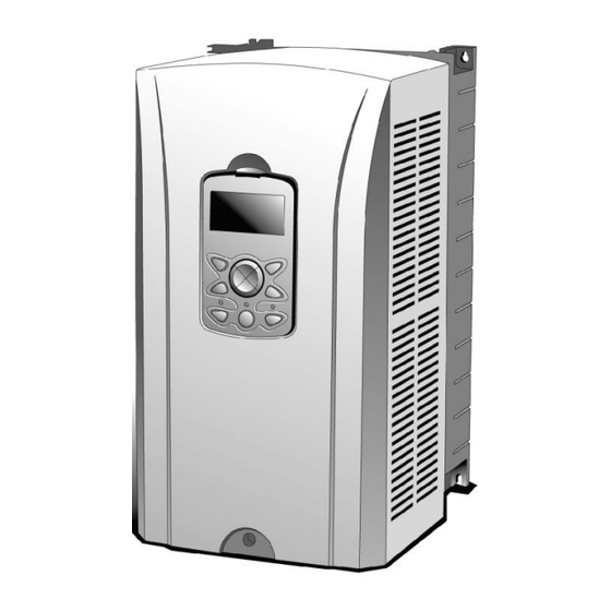
Page 9: Appearance And Part Name
Appearance and Part Name 3 Appearance and Part Name Display LED Name Usage DATA_EX LED Always on when Profibus is online. ERROR LED Illuminates when an option or body malfunctions. Illuminates when power is supplied to the inverter after CPU LED installing the communication board to the inverter. - Page 10 Appearance and Part Name Communication network terminals PROFIBUS Signal Description Connector None None 24 V Output GND RxD/TxD-P Received/Transmitted Data Plus CTRL-P Control signal for a repeater DGND Signal GND 5 V for termination resistance 24 V Output - Positive RxD/TxD-N Received/Transmitted Data - Negative CTRL-N...
-
Page 11: How To Fit Option
How to fit option 4 How to fit option 4.1 Mounting option to the inverter body Turn off the power. Remove the front cover of the iS7 and connect the connector as shown below. Secure it to the main body using the included screw. Power on the inverter and verify that Profibus is recognized in "CNF 31: Option-1 Type". -
Page 12: Structure Of Profibus Signal Line Connector And Connector Connection Method
How to fit option 4.2 Structure of Profibus signal line connector and connector connection method Incoming line: Connect the green line to A1 and red to B1. Outgoing line: Connect the green line to A2 and red to B2. Connect the shield to the clamp on the connector. When installing the connector on the end, install the cables on A1 and B1. -
Page 13: Grounding Option
How to fit option 4.3 Grounding option When using a ground on a communication cable (shielded cable), connect as follows. The ground cable is not included in the product package. Remove the communication option cover. Connect the ground wire using the *screw to the left of the communication option. Remove the communication option cover if it is difficult to handle the lines on the ground wire. - Page 14 How to fit option Connect the ground of the communication option separately from the ground (CM) of the inverter * See Ground part. Recommended Screw torque Screw size Lug type wiring thickness [kgf.cm] [mm2](AWG) Complies with lug M3x6 Circular or Y-type specification...
-
Page 15: Profibus Parameters
Profibus parameters 5 Profibus parameters 5.1 Setting station address Minimum Maximum Location on KeyPad value value Field Bus ID 07 in COM Group The station address is a unique value that distinguishes each node in the Profibus network. Therefore, other devices cannot share the same value. You can change the station address by manipulating the keypad. -
Page 16: Setting Address For The Output Data
Profibus parameters 5.4 Setting address for the output data Sets the address as many times as the number of data to output. Maximum Minimum value Location on KeyPad value Para Status 1~8 0h0000 0hFFFF 31-38 in COM Group 5.5 Setting address for the input data Sets the address as many times as the number of data to input. -
Page 17: Setting Profibus Bit Swap
Profibus parameters 5.7 Setting Profibus Bit Swap You can set whether the LSB and MSB bits in the data transmitted during network communication will be swapped. (This setting is required if the upper-level controller has an interface that reads the LSB and MSB data from the PROFIBUS communication module in a reverse order.) Setting Keypad Parameter Number... -
Page 18: Profibus Dp Profile
Profibus parameters 5.9 Profibus DP Profile Displays the control operation mode for inverter operation. These parameters cannot be changed on the keypad and can only be changed on the master. The control operation mode shows the operation mode status set by the master, and the meaning of each value is as follows: Value meaning Remark... -
Page 19: Profibus Dp Module Reset
Profibus parameters 5.11 Profibus DP Module Reset Parameter for initializing the PROFIdrive parameter value of the communication option to zero. As soon as the corresponding value is set to 1, the values of p944, p947, and p953 to be initialized are initialized to 0. 5.12 Profibus DP PROFIdrive Value Parameter used when the value applied in the COM-11 Profibus DP Profile is set to PROFIdrive Profile (1). -
Page 20: Basic Operation
Basic operation 6 Basic operation When the inverter power is on or resets: The CPU LED blinks when power is turned on normally. The ERR LED turns on if there is something wrong. The configuration is performed through the keypad. The DATA_EX LED indicating the Profibus communication status turns on when communication with the Master station is started as set. -
Page 21: Abnormal Operation And Countermeasures
Abnormal operation and countermeasures 7 Abnormal operation and countermeasures Three LEDs (DATA_EX, ERR, CPU) located at the bottom of the product display the status of the device and network. The display status of each LED shows the current status. 7.1 DATA_EX LED operation and countermeasures in case of malfunction LED Status Cause... -
Page 22: Cpu Led Operation And Countermeasures In Case Of Malfunction
Abnormal operation and countermeasures 7.2 CPU LED operation and countermeasures in case of malfunction Status Cause Measures Poor power Check the power supply to the connection to inverter. Power supply inverter/poor Check if the inverter has tripped. failure contact between Check the connection of the inverter and option connector to the inverter. -
Page 23: System Configuration And Transmission Specification
System configuration and transmission specification 8 System configuration and transmission specification 8.1 Methods and specifications for installing terminating resistance... -
Page 24: Maximum Transmission Distance Specification
System configuration and transmission specification 8.2 Maximum transmission distance specification Communication Max. Segment Length Max. Extension Length speed (Kbps) 9.60 1000 m / 3278 feet 10000 m / 32786 feet 19.20 1000 m / 3278 feet 10000 m / 32786 feet 45.45 1000 m / 3278 feet 10000 m / 32786 feet... -
Page 25: Preferences And Other Features
The configuration software requires this file. Be sure to use the GSD file for the iS7. The file can be downloaded from the LS ELECTRIC homepage (http://www.ls-electric.com). * Apply the GSD that matches the software version of the option module. -
Page 26: Extended Diagnostic
Preferences and Other Features 9.3 Extended Diagnostic It is a safety-related function that generates diagnostic in the Master when an inverter trip or an optional trip occurs. There are currently five extended diagnostics defined: Cannot Connect between the Main and the Option: Poor communication connection between inverter and option. -
Page 27: Communication Parameters
Communication Parameters 10 Communication Parameters 10.1 Map Structure of the iS7 Inverter full communication parameters Area Address Parameter type iS7 Series compatible 0h0000~0h00FF Common Areas 0h0100~0h01FF Parameters registered with COM Grp 0h0200~0h023F Parameters registered with Usr Grp Parameter registration type area 0h0240~0h027F Parameters registered with Macro Grp 0h0280~0h02FF... -
Page 28: Parameter Groups For Periodic Data Transmission
Communication Parameters 10.2 Parameter Groups for Periodic Data Transmission Communication can be performed using the address registered in the communication function group (COM). 0h100 to 0h107: Inverter status parameter registered in status para # in the keypad parameter COM group 0h110 to 0h117: Inverter control parameter registered in control para # in the keypad parameter COM group. -
Page 29: Parameter Groups For User And Macro Grp Transport
Communication Parameters 10.3 Parameter Groups for User and Macro Grp Transport 0h200 to 0h23F: User Grp parameter currently registered Address Parameter Content assigned by Bit 0h0200 User Grp. Code 1 Parameter value registered in U&M>USR->1 0h0201 User Grp. Code 2 Parameter value registered in U&M>USR->2 0h0202 User Grp. -
Page 30: 0H200 To 0H23F: User Grp Parameter Currently Registered
Communication Parameters 10.4 0h200 to 0h23F: User Grp parameter currently registered Address Parameter Content assigned by Bit 0h0240 Macro Grp. Code 1 Parameter value registered in U&M>MC->1 0h0241 Macro Grp. Code 2 Parameter value registered in U&M>MC->2 0h0242 Macro Grp. Code 3 Parameter value registered in U&M>MC->3 0h0243 Macro Grp. -
Page 31: Product Size
Product Size 11 Product Size Option size... -
Page 32: Communication Profile
Communication Profile 12 Communication Profile The communication profile represents the procedure for control commands (i.e., control word, status word, references, and actual values, etc.) between the Master and the Slave (inverter). Data transmission between the PROFIBUS DP Master and the Slave is performed through the IN/OUT data field. The Master controls the data by recording it in the OUT data of the Slave (inverter), the Slave (inverter) responds by delivering the contents of the IN data to the Master. -
Page 33: Profidrive Profile
Communication Profile The Profibus DP communication module can be used in combination of process data and parameter data, depending on the use of the profile and Telegram. Process data Process data OUT : For controlling drive Process data IN : Is used for fast monitoring of the drive Parameter data Used for Write/Read parameters and variables. - Page 34 Communication Profile Figure 5. PROFIdrive State machine The details of the control word and status word used in the status machine above are as follows:...
-
Page 35: Control Word(Stw1)
Communication Profile 12.1.1 Control word(STW1) Name Value Description Ready to operate (Operational status by PLC) NOT ready to operate OFF1 (Inoperable condition by PLC) No OFF2 Maintains the current operating condition. OFF2 Coast Stop: Stops the motor by Free Run Stop. (Free Run Stop) No OFF3 Maintains the current operating condition. -
Page 36: Status Word(Zsw1)
Communication Profile Name Value Description Jog2 ON/OFF Not supported Controls the inverter using control word (STW1) Control By PLC received from the PLC via Profibus DP communication. No Control By Ignores the control word (STW1) received from the PLC via Profibus DP communication. 11 ~ 15 Reserved 12.1.2 Status word(ZSW1) -
Page 37: Setpoint Value
Communication Profile Name Value Description Indicates that the actual rotational frequency of the Speed Error out motor has not been reached at the command of tolerance frequency ("Setpoint value"). Control Requested Indicates the bit 10 value of the currently entered No Control control word (STW1). -
Page 38: Actual Speed Value
(100). * See Figure 4 I/O profile. 12.3 LS Drive Profile Standardization profile as defined by LS ELECTRIC. This is the profile used in the drive speed control mode, and the control/status can be checked by the control word and the status word. -
Page 39: Control Word
Communication Profile Figure 6. LS Drive Profile state machine 12.3.1 Control word Name Value Description No control commands Stop Stop command No control commands Move forward Move forward command No control commands Reverse command Reverse operation command No control commands Defect released Initialize fault status No control commands... -
Page 40: Status Word
Communication Profile Name Value Description Cancel remote RAMP source command authority RAMP source command authority Grant remote RAMP source command authority 12.3.2 Status word Name Value Description Not stopped Stop Stopped by the stop mode Not moving forward Moving forward Moving forward Not moving in reverse Moving in reverse... -
Page 41: Setpoint Value
Communication Profile Name Value Description No control commands Move forward command Received move forward command No control commands Move in reverse command Received move reverse command Remote driving command authority Preparing operation canceled command Remote driving command authority granted Remote RAMP source command authority canceled Preparing RAMP source command... -
Page 42: Communication Protocol
Communication Protocol 13 Communication Protocol 13.1 Cyclical message types For the Profibus DP communication module and master to proceed with data exchange, set how many words of data you want to send and receive. Telegram settings are basically set by the Master during I/O configuration and cannot be set by the communication module itself. -
Page 43: Standard Telegram1
Communication Protocol OUT area: Data (control data) sent from the Master to Slave. IN area: Data sent from Slave to Master (actual data). Parameter data area ID : Parameter identification(type and number) IND : subIndex of parameter Value : Request/Response Parameter value PKW : Parameter ID/value Process data STW1 : Control word... -
Page 44: Vender Specific Telegram
Communication Protocol 13.1.3 Vender Specific Telegram Instead of using a separate standardized telegram, depending on the Para Control Num and the Para Status Num, the number of words to use is determined. PZD 1-8 is set according to the parameter address value specified in Para Control-1-8, Para Status-1-8. - Page 45 Communication Protocol The request label is used by the Master when sending data to the Slave, and the response label is used when the Slave checks for positive or negative responses. See the table below for details Response label Request labels (from master to slave) (Acknowledgement from slave to master) Response identifier...
- Page 46 Communication Protocol Response label (Acknowledgement from slave to master) Task cannot be executed, followed by error number No parameter change rights for PKW interface Parameter data signal (word) *not supported Parameter data signal (double word) *not supported This means that the command cannot be executed if the response identifier value is 7 and returns an error code to the value (parameter value) of the response packet.
- Page 47 Communication Protocol Here is how to assign the PROFIdrive and Drive parameters to the parameter identification part within the PPO type: The group column corresponds to the parameter number (PNU) of the identifier. The subindex column corresponds to the IND portion of the parameter index. PROFIdrive Parameters Parameter number(decimal) Group...
- Page 48 Communication Protocol The parameter value can be set according to the read/write properties of each specified parameter, and the value of the requested parameter number can be read or changed. Only Byte 6 and 7 data are valid because they do not support 32-bit data, just 16-bit data.
-
Page 49: Acyclic Parameter Data Transfer (Dp-V1)
Communication Protocol 13.2.2 Acyclic Parameter data transfer (DP-V1) It is a method of periodically requesting/responding parameters by accessing from Master class 2 without being dependent on a separate telegram type. The method to use the write/read service for the drive parameters is as follows: Figure 8. - Page 50 Communication Protocol PROFIBUS DP-V1 frames are mapped inside standard PROFIBUS frames as follows: PROFIBUS frame PROFIBUS PROFIBUS DU(Data Unit) header Trailer Parameter Request header Parameter Parameter (write request or address value DP-V1 (SD SSAP) read request) (FCS, ED) header Parameter Response Parameter value header...
- Page 51 Communication Protocol Error responses of DP-V1 function Byte Field Description Allowed values 0hDE = slave response error in read Function PROFIBUS DP request. Function Codes 0hDF = slave response error in write Number request. Displays the Error information values for the error-decoding Decode DP-V1...
- Page 52 Communication Protocol Error class Meaning Error code 2 = Resource busy 3 = Resource unavailable 4…7 = Reserved 8…15 = User-specific 13…15 User-specific Parameter Requests Each parameter request via PROFIBUS DP-V1 consists of three elements: Parameter value Request header Parameter address (only in Change requests) Parameter Request Byte...
- Page 53 Communication Protocol Parameter Request Values the parameter with Change Parameter (0h02). Only array type parameters are applied. 12, 13 Values Requested Value 1) If you request multiple request IDs 01h (parameter request), it is repeated with n. 2) The format, number of values, and values fields are repeated for other parameters only if the request ID is 02h (parameter change).
-
Page 54: Profidrive Parameters
PROFIdrive Parameters 14 PROFIdrive Parameters 14.1 Supported Parameters Parameters Data Type Description Displays the selected node address in the FBus ID Unsigned16 (COM-07). Displays the selected cyclic telegram in the master's I/O configuration. 1 : Standard Telegram 1 100 : Vender Specific Telegram 101 : PPO Type 1 (PKW 4/4 + PZD 2/2) 102 : PPO Type 2 (PKW 4/4 + PZD 6/6) Unsigned16... - Page 55 PROFIdrive Parameters Parameters 1 = 19.2 kbit/s 2 = 93.75 kbit/s 3 = 187.5 kbit/s 4 = 500 kbit/s 6 = 1.5 Mbit/s 7 = 3 Mbit/s 8 = 6 Mbit/s 9 = 12 Mbit/s 11 = 45.45 kbit/s 255 = Invalid baud rate A value for a five-word (16-bit) array that displays information about the communication module.
-
Page 56: Description Of The Pnu[944] Fault Message Counter And The Pnu[947] Fault Number
PROFIdrive Parameters 14.2 Description of the PNU[944] Fault Message Counter and the PNU[947] Fault Number Each time the inverter encounters a fault, the PNU[944] Fault Message Counter value increases by one, and the fault is stored in the PNU[947] Fault Number variable. The PNU[947] Fault Number can store eight fault situations, and each fault situation can store eight fault messages. - Page 57 PROFIdrive Parameters Trip Name Fault Message Overload Trip Underload Trip Inverter Overload Trip E-Thermal Trip Ground Fault Trip Out phase open trip In phase open trip Overspeed Overspeed Deviation NTC Trip Overcurrent Trip Overvoltage Trip External Trip Arm Short Overheat Trip Fuse Open Trip MC Fail Trip Encoder Error Trip...
- Page 58 PROFIdrive Parameters Trip Name Fault Message Lost Command Keypad Lost Command Reserved Reserved Reserved Reserved Reserved Reserved Reserved Reserved Reserved Reserved Reserved Reserved ADC error EEPROM error Watchdog-1 error Watchdog-2 error Gate Drive Power Loss Reserved Reserved Reserved Reserved Reserved Reserved Reserved Reserved...
-
Page 59: M Records
I&M records 15 I&M records The I&M function is one of the customer support services that is used to check basic information during the start-up and maintenance of the module Content Size Description Function_Num 1 Byte Slot_Number 1 Byte 0…255(deciaml) DP-V1 header Index 1 Byte... - Page 60 This product has been manufactured through strict quality control and test procedures by LS ELECTRIC. The warranty period is 12 months after installation or 18 months from the manufacturing date if the installation date is not filled out. However, the warranty period may vary depending on the terms of sales.
- Page 61 (fire, flood, earthquake, gas accidents etc.) modifications or repair by unauthorized persons If the LS ELECTRIC nameplate is not attached to the product. expired warranty period Visit Our Website Visit us at LS ELECTRIC homepage (https://www.ls-electric.com) for detailed service...
Need help?
Do you have a question about the SV-iS7 Series and is the answer not in the manual?
Questions and answers