
Related Manuals for Emerson PACSystems VersaSafe IC220SDL963


Summary of Contents for Emerson PACSystems VersaSafe IC220SDL963
- Page 1 User Manual GFK-2843A Jan 2020 PACSystems VersaSafe ENHANCED SAFETY LOGIC MODULE, SAFE OUTPUT 24VDC, 8 POINTS USER MANUALS VersaPoint MODULE: IC220SDL963...
-
Page 2: Table Of Contents
User Manual Contents GFK-2843A Jan 2020 Contents Chapter 1: For your safety ............1 General safety notes .................... 1 Electrical safety ....................2 Safety of the machine or system ................3 Safety when starting applications ................ 4 Directives and standards..................5 Correct usage ...................... - Page 3 User Manual Contents GFK-2843A Jan 2020 Assembly and removal ..................22 4.1.1 Unpacking the module ................22 4.1.2 General ....................22 4.1.3 Setting the DIP switches ................23 4.1.4 Assembly and removal of the safety module ..........24 Electrical installation ..................27 4.2.1 Electrical installation of the VersaPoint station ........
- Page 4 User Manual Contents GFK-2843A Jan 2020 Chapter 9: Maintenance, repair, decommissioning, and disposal 57 Maintenance ..................... 57 Repair ........................ 57 Decommissioning and disposal ................. 57 Chapter 10: Technical data and ordering data ......58 10.1 System data ...................... 58 10.1.1 VersaPoint ....................58 10.1.2 VersaSafe system ..................
- Page 5 User Manual Contents GFK-2843A Jan 2020 A-7.1 Configuration and parameterization using the VersaConf Safety software tool ................83 A-7.2 Downloading the configuration and parameter data record ....85 Safe state ......................85 Time response in the VersaSafe system ............. 85 A-9.1 Typical response time ................
- Page 6 Changes, modifications, and/or improvements to equipment and specifications are made periodically and these changes may or may not be reflected herein. It is understood that Emerson may make changes, modifications, or improvements to the equipment referenced herein or to the document itself at any time.
-
Page 7: Chapter 1: For Your Safety
User Manual Chapter 1 GFK-2843A Jan 2020 Chapter 1: For your safety Purpose of this manual The information in this document is designed to familiarize you with how the IC220SDL963 safety module works, its operating and connection elements, and its parameter settings. -
Page 8: Electrical Safety
Do not carry out any repairs In the event that an error cannot be removed, please contact Emerson immediately, engage a service engineer or send the faulty module directly to Emerson. Do not open the It is strictly prohibited to open the safety module housing. In... -
Page 9: Safety Of The Machine Or System
User Manual Chapter 1 GFK-2843A Jan 2020 Direct/indirect Ensure that all components connected to the system are contact protected against direct and indirect contact according to VDE 0100 Part 410. In the event of an error, parasitic voltages must not occur (single-fault tolerance). This can be achieved by: •... -
Page 10: Safety When Starting Applications
User Manual Chapter 1 GFK-2843A Jan 2020 " on page 5, as well as a test report (checklist) for and standards validating the safety function (see " " on page 94). checklists The target safety integrity level (SIL according to IEC 61508-2, SIL CL according to EN 62061 or performance level and category according to EN ISO 13849-1) is ascertained on the basis of the risk analysis. -
Page 11: Directives And Standards
For the standards observed by the module, please refer to the certificate issued by the approval body and the EC declaration of conformity. These documents are available on the Internet at https://www.emerson.com/Industrial-Automation-Controls/support. Correct usage Only use the VersaSafe system in accordance with the instructions in this section. -
Page 12: Documentation
Documentation Latest Make sure you always use the latest documentation. Changes or documentation additions to this document can be found on the Internet at https://www.emerson.com/Industrial-Automation- Controls/support. VersaSafe When working on the VersaSafe system and its components, you System must always keep this user manual and other items of product documentation on hand and observe the information therein. -
Page 13: Chapter 2: Product Description
User Manual Chapter 2 GFK-2843A Jan 2020 Chapter 2: Product description Note about the system description The VersaSafe system is described in "VersaSafe system" on page 67. In the description of the IC220SDL963 safety module, it is assumed that you are familiar with the VersaSafe system. -
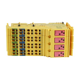
Page 14: Structure Of The Safety Module
User Manual Chapter 2 GFK-2843A Jan 2020 Structure of the safety module Figure 1: Structure of the safety module 1. Data jumpers (local bus) 2. Electronics base with labeling including hardware/firmware/firmware version designation (not shown) 3. Switch for setting the transmission speed 4. -
Page 15: Housing Dimensions
User Manual Chapter 2 GFK-2843A Jan 2020 Housing dimensions Figure 2: Housing dimensions (in mm) Safe digital outputs The safety module has safe positive switching digital outputs, which can be used as follows: • For two-channel assignment: Four two-channel outputs —... - Page 16 User Manual Chapter 2 GFK-2843A Jan 2020 Technical data For the technical data for the safe inputs, please refer to page 62. Parameterization The individual safe digital outputs of a safety module can be parameterized differently. This means that the outputs can be adapted to various operating conditions and different safety integrity levels (SIL, SIL CL, Cat., PL) can be implemented.
- Page 17 User Manual Chapter 2 GFK-2843A Jan 2020 WARNING Unintentional machine startup If the process does not tolerate this behavior, actuators with sufficient inertia must be used. In general, the load must not be so dynamic that it causes dangerous states within 1 ms. Quick actuators, which offer a safety-related response to pulses in under 1 ms, may not generally be used.
-
Page 18: Connection Options For Actuators Depending On The Parameterization
User Manual Chapter 2 GFK-2843A Jan 2020 Connection options for actuators depending on the parameterization Actuators that meet various safety requirements depending on the parameterization can be connected to the outputs. For connection examples, please refer to Section 6, "Connection examples for safe outputs". The maximum achievable SIL/SIL CL/Cat./PL is specified in the table. - Page 19 User Manual Chapter 2 GFK-2843A Jan 2020 Table 3: Local diagnostic and status indicators Green LED Diagnostics OFF: Communications power not present Flashing at 0.5 Hz: Communications power present, local bus not active Flashing at 4 Hz: Communications power present, error at the interface between previous and flashing terminal (the terminals after the flashing terminal cannot be addressed).
-
Page 20: Safe State
User Manual Chapter 2 GFK-2843A Jan 2020 Red ON: Short circuit/overload of an output (This diagnostic message is stored temporarily on the module. The message is stored in the volatile memory and will be lost after a voltage reset.) Important In the event of an error (red LED ON), the output is switched off until the acknowledgment sent by the controller is received by the safety module (see also "Safe digital output errors"... -
Page 21: Device Errors
User Manual Chapter 2 GFK-2843A Jan 2020 The relevant diagnostic message is transmitted to the controller (see "Safe digital output errors" on page 51). For information on which errors are detected and when, please refer to "Connection examples for safe outputs" on page 35. Important If an error occurs on a channel of an output parameterized as “two-channel”, the other corresponding channel also enters the safe state. -
Page 22: Parameterization Errors
User Manual Chapter 2 GFK-2843A Jan 2020 2.8.4 Parameterization errors Parameterization errors are indicated: • As long as the module is not parameterized • In the event of faulty parameterization Parameterization errors cause the entire module to enter the safe state. The FS LED on the safety module flashes. -
Page 23: Chapter 3: Versapoint Potential And Data Routing, And Versapoint Connectors
User Manual Chapter 3 GFK-2843A Jan 2020 Chapter 3: VersaPoint potential and data routing, and VersaPoint connectors VersaPoint potential and data routing For operation, the safety module must be integrated in an VersaPoint station within the VersaSafe system. The bus signals are transmitted via the VersaPoint data jumpers. The required supply volt- ages are transmitted via the VersaPoint potential jumpers. -
Page 24: Supply Voltage U
User Manual Chapter 3 GFK-2843A Jan 2020 Supply voltage U Supply the supply voltage at a bus coupler or a power terminal. It is supplied to the safety module via the VersaPoint potential jumper U WARNING Loss of the safety function when using unsuitable power supplies Please note for the voltage supply at the bus coupler or power terminal that: Only power supplies according to EN 50178/VDE 0160 (PELV) may be used. -
Page 25: Terminal Point Assignment
User Manual Chapter 3 GFK-2843A Jan 2020 WARNING Loss of functional safety due to parasitic voltages Supply the supply voltages U and U at a bus coupler and/or a power terminal from the same power supply unit, so that the loads of IC220SDL963 are not affected by parasitic voltages in the event of an error. - Page 26 User Manual Chapter 3 GFK-2843A Jan 2020 Important Only use the connectors supplied with the module or connectors that are approved as re- placement items (see "Ordering data: accessories" on page 65). The following applies for the tables below: • All outputs are safe digital outputs •...
- Page 27 User Manual Chapter 3 GFK-2843A Jan 2020 Table 7: Terminal point assignment for connector 4 Terminal point Signal Channel assignment OUT3_Ch1 Output 3, channel 1 OUT3_Ch2 Output 3, channel 2 Not used Not used 0 V (GND) Channel 1 and channel 2 0 V (GND) Channel 1 and channel 2 WARNING...
-
Page 28: Chapter 4: Assembly, Removal, And Electrical Installation
User Manual Chapter 4 GFK-2843A Jan 2020 Chapter 4: Assembly, removal, and electrical installation Assembly and removal 4.1.1 Unpacking the module The module is supplied in an ESD box together with a package slip with installation instructions. Please read the complete package slip carefully. The module may only be installed and removed by qualified personnel. -
Page 29: Setting The Dip Switches
User Manual Chapter 4 GFK-2843A Jan 2020 4.1.3 Setting the DIP switches Important Set the DIP switches accordingly for your application before assembling the module in an VersaPoint station. The switches cannot be accessed when the safety terminal is installed in the VersaPoint station. -
Page 30: Assembly And Removal Of The Safety Module
User Manual Chapter 4 GFK-2843A Jan 2020 Important Only use devices with a uniform transmission speed within an VersaPoint station (a local bus). It is not possible to operate a mixture of devices with different transmission speeds. 10-pos. DIP switch: address The island number is set via the 10-pos. - Page 31 User Manual Chapter 4 GFK-2843A Jan 2020 Assembly Important • Set the DIP switches prior to assembly (see "Setting the DIP switches" on page 23). The DIP switches cannot be accessed when the safety module is installed in the VersaPoint station. •...
- Page 32 User Manual Chapter 4 GFK-2843A Jan 2020 Figure 8: Inserting the connector Removal • Disconnect the power to the station. • Before snapping on the safety module, remove the connectors from the safety module and the adjacent connector from the neighboring VersaPoint terminal on the left.
-
Page 33: Electrical Installation
User Manual Chapter 4 GFK-2843A Jan 2020 Figure 10: Removing the safety module base Electrical installation WARNING Electric shock/unintentional machine startup Prior to electrical installation, disconnect the power to the system and make sure that it cannot be switched on again unintentionally. Make sure installation has been completed before switching the power back on. -
Page 34: Electrical Installation Of The Safety Module
User Manual Chapter 4 GFK-2843A Jan 2020 4.2.2 Electrical installation of the safety module Important During installation, always observe the instructions in "Electrical safety" on page 2. Take measures to prevent the incorrect connection, polarity reversal, and manipulation of connections. The supply voltages are supplied at a bus coupler and/or a power terminal and are supplied to the safety module via the potential jumpers. - Page 35 User Manual Chapter 4 GFK-2843A Jan 2020 • Insert the assembled connectors in the corresponding module slot (see "Terminal point assignment" on page 19). • Mark all connections to prevent connections to the VersaPoint connectors being mixed up (see GFK-2736 user manual). Assembly, removal, and electrical installation...
-
Page 36: Chapter 5: Parameterization Of The Safety Module
User Manual Chapter 5 GFK-2843A Jan 2020 Chapter 5: Parameterization of the safety module Parameterization of the safety module in a VersaSafe system Important For information on the configuration and parameterization of the VersaSafe system, please refer to "Configuration and parameterization using the VersaConf Safety software tool"... -
Page 37: Parameterization Of The Safe Outputs
User Manual Chapter 4 GFK-2843A Jan 2020 The supply voltage must be present and the local bus must be in the RUN state when downloading. The module cannot be operated if it is not parameterized. In this case, the FS LED flashes. The module is ready to operate if the parameters for all outputs are valid and transmitted without errors. - Page 38 User Manual Chapter 4 GFK-2843A Jan 2020 Parameterization Value range Remark OUT0 - OUT3 1 to 63 Switch-off delay for Time conversion according to the parameterization of stop category 1 the “Value range of switch-off delay for stop category 1” parameter.
-
Page 39: Behavior Of The Outputs In The Event Of Enabled Switch-Off Delay For Stop Category 1
User Manual Chapter 4 GFK-2843A Jan 2020 Important If the switch-off delay for stop category 1 is parameterized with a value less than 150 ms, this value is rejected as a parameterization error (error code 028x Two-channel Please note the following for two-channel parameterization: parameterization Ensure that the values for the switch-off delay for stop category 1 are the same for both channels. - Page 40 User Manual Chapter 4 GFK-2843A Jan 2020 WARNING Exception for delayed shutdown: – In the event of an error (excluding bus errors) the affected outputs are switched off immediately (without delay). In this case, only stop category 0 is supported. For the switch-off operation, please take into consideration the following: •...
-
Page 41: Chapter 6: Connection Examples For Safe Outputs
The following examples only describe the options for the electrical connection of controlled devices/actuators to the safe outputs. Should you have any questions regarding applications to be implemented, please contact Emerson. The following are specified for each example: • Basic specifications The main data for the example is specified in the table. -
Page 42: Notes On The Protective Circuit For External Re- Lays/Contactors (Freewheeling Circuit)
User Manual Chapter 6 GFK-2843A Jan 2020 Therefore, for example, only errors between outputs, which are on the same connector, are described. For example, in the event of correct installation, cross circuits with outputs of other connectors cannot occur. Important For all examples, please also observe the measures specified in the individual tables, which must be taken to achieve the specified SIL/SIL CL/Cat./PL and all measures ac- cording to standards IEC 61508-2, EN 62061, EN 954-1, and EN ISO 13849-1 to achieve... -
Page 43: Measures Required To Achieve A Specific Safety Integrity Level
User Manual Chapter 6 GFK-2843A Jan 2020 Important • Limit the voltage induced on circuit interruption to < -15 V (e.g., with RC elements, suppressor diodes or varistors). • Please note that the freewheeling circuit affects the dropout time and the service life of the contactor. - Page 44 User Manual Chapter 6 GFK-2843A Jan 2020 Cat. 2 • Use proven and basic safety principles according to EN ISO 13849-2. • Use appropriately qualified actuators (see Section "Requirements for controlled devices/actuators" on page 10). • Please note that mechanical failure of the switching device can result in the loss of the safety function.
-
Page 45: Single-Channel Assignment Of Safe Outputs
User Manual Chapter 6 GFK-2843A Jan 2020 • All errors that cannot be detected can result in the loss of the safety function. Take appropriate measures to prevent such errors. Suitable measures include, for example, protected cable installation or double insulation. Please note the information in the following tables. - Page 46 User Manual Chapter 6 GFK-2843A Jan 2020 Basic specifications Actuator Single-channel Two-channel Achievable SIL/SIL CL/Cat./PL SIL 2/SIL CL 2/Cat. 2/PL c SIL 2/SIL CL 2/Cat. 3/PL d WARNING Loss of electrical and functional safety • To achieve the specified safety integrity level, please refer to Section "Measures required to achieve a specific safety integrity level"...
- Page 47 User Manual Chapter 6 GFK-2843A Jan 2020 Error type Remark Dete Diagnosti Loss ction of SF Interrupt Cable interrupt between None Detect errors using external monitoring. output and actuator or Please take into consideration all the possible between actuator and errors for the actuator used.
-
Page 48: Two-Channel Assignment Of Safe Outputs
User Manual Chapter 6 GFK-2843A Jan 2020 Two-channel assignment of safe outputs For two-channel assignment of the safe outputs, two adjacent outputs are always used. This assignment is fixed and cannot be parameterized (see Section "Two-channel" on page 31). Figure 14: Two-channel assignment of outputs K1 (R) and K2 (R) represent the forcibly guided N/C contacts for monitoring the state of the relay (readback contacts). - Page 49 User Manual Chapter 6 GFK-2843A Jan 2020 WARNING Loss of electrical and functional safety • To achieve the specified safety integrity level, please refer to Section "Measures required to achieve a specific safety integrity level" on page 37. • Please note that in order to achieve the specified PL, the actuator must have a medium level of diagnostic coverage (90% to 99%) and medium MTTFd.
- Page 50 User Manual Chapter 6 GFK-2843A Jan 2020 Error type Remark Detect Diagnos Loss tics of SF Error in the wiring Interrupt Cable interrupt between None Detect errors using external monitoring. output and actuator or Please take into consideration all the between actuator and possible errors for the actuator used.
- Page 51 User Manual Chapter 6 GFK-2843A Jan 2020 Parameterization Parameterized as Remark Channel 1 Channel 2 Test pulses (output disabled) (in software: Enabled Enabled test impulses (output switched off)) According to the “Value range of switch-off delay for stop category 1” and “Switch-off delay for stop category 1”...
-
Page 52: Chapter 7: Startup And Validation
User Manual Chapter 7 GFK-2843A Jan 2020 Chapter 7: Startup and validation Initial startup Table 16: Steps for parameterization and configuration (via VersaConf Safety Version 2.8 or later) Step Relevant section and literature Carry out the necessary parameterization. "Parameterization of the safety module" on page 30 Carry out the necessary parameterization for User manuals for the modules used the island satellites. - Page 53 User Manual Chapter 7 GFK-2843A Jan 2020 Step Relevant section and literature Once the operating voltage has been applied: • If possible, measure the wave form of the voltages to ensure that there are no deviations. • Measure the output voltages on the module, as well as the supply voltages, which supply connected loads (e.g., motor) to ensure that they are in the...
-
Page 54: Restart After Replacing A Safety Module
User Manual Chapter 7 GFK-2843A Jan 2020 Restart after replacing a safety module 7.2.1 Replacing a safety module WARNING Unintentional machine startup Do not assemble or remove the module while the power is connected. Before assembling or removing the module, disconnect the power to the module and the entire VersaPoint station and ensure that it cannot be switched on again. - Page 55 User Manual Chapter 7 GFK-2843A Jan 2020 • The safety module has been parameterized correctly • The signals used in your safety logic have been linked to the safe actuators correctly Perform a function test and error simulation. Please observe the checklist "Validation" on page 102 during validation. Startup and validation...
-
Page 56: Chapter 8: Errors: Messages And Removal
“Acknowledgment” column in the tables below. Important If diagnostic codes are indicated by the system, which do not appear in the tables below, please contact Emerson. To remove the cause of an error, please proceed as described in Error removal the “Solution”... -
Page 57: Safe Digital Output Errors
User Manual Chapter 8 GFK-2843A Jan 2020 Acknowledgment To remove the error, evaluate the PUR and OAR bits in the diagnostic register of the IC220SDL963 (see Section A 4). These specify whether a power up is expected or whether an acknowledgment is required. -
Page 58: Supply Voltage Errors
User Manual Chapter 8 GFK-2843A Jan 2020 Error cause Remark Effect Solution Diagnostic code Acknowle (hex) dgment at the output X062: OUT2_Ch1 X069: OUT2_Ch2 failed X063: OUT3_Ch1 X06A: OUT3_Ch2 Hardware fault X091 Detected by All module out- Power up with Yes (1) internal tests. -
Page 59: General Errors
User Manual Chapter 8 GFK-2843A Jan 2020 Undervoltage at U Supply voltage U is measured. If U < 17 V, a diagnostic message is generated. General errors Table 21: General errors Error Diagnos Remark Effect Solution Ackno cause tic code wledg (hex) ment... - Page 60 User Manual Chapter 8 GFK-2843A Jan 2020 Table 23: Parameterization errors Diagnostic code Short description Solution (hex) (dec) X21n The parameterized Correct value and resend shutdown time for the parameter data to the X210: OUT0_Ch1&2 528: OUT0_Ch1&2 indicated output is outside module.
-
Page 61: Connection Errors To Satellites
User Manual Chapter 8 GFK-2843A Jan 2020 Connection errors to satellites Table 24: Connection errors to satellites Error cause Short description Solution Diagnos Acknowledgme tic code (hex) (hex) Incorrect X3FC Incorrect island number Check switch position Reload project. set at the IC220SDL963. and value in software island number and adapt accordingly. - Page 62 User Manual Chapter 8 GFK-2843A Jan 2020 If in the event of failure the safety module is replaced, please proceed as described in Chapter 4, "Assembly, removal, and electrical installation" and Section "Restart after replacing a safety module" on page 48. Errors: messages and removal...
-
Page 63: Chapter 9: Maintenance, Repair, Decommissioning, And Disposal
Repair Repair work may not be carried out on the safety module. In the event of an error, send the module to Emerson. It is strictly prohibited to open the safety module. In order to prevent the manipulation of the module and to detect the unauthorized opening of the module, a security seal is applied to the module. -
Page 64: Chapter 10: Technical Data And Ordering Data
User Manual Chapter 10 GFK-2843A Jan 2020 Chapter 10: Technical data and ordering data 10.1 System data 10.1.1 VersaPoint For system data, please refer to the following user manual: VersaPoint Automation terminals of the VersaPoint product range GFK-2736 10.1.2 VersaSafe system VersaSafe system Shutdown time t 15ms... - Page 65 User Manual Chapter 10 GFK-2843A Jan 2020 General data Air pressure Operation 80 kPa to 108 kPa (up to 2000 m above sea level) Storage/transport 66 kPa to 108 kPa (up to 3500 m above sea level) Degree of protection IP20 Housing material Plastic PBT, self-extinguishing (V0)
- Page 66 User Manual Chapter 10 GFK-2843A Jan 2020 Safety characteristic data according to IEC 61508/EN 61508 Achievable SIL SIL 2 (single-channel) SIL 3 (two-channel) Depends on the parameterization and wiring (see "Connection options for actuators depending on the parameterization" on page 12and "Connection examples for safe outputs"...
- Page 67 User Manual Chapter 10 GFK-2843A Jan 2020 Safety characteristic data according to EN ISO 13849-1 Diagnostic coverage (DC) Mean time to dangerous failure For single-channel assignment: 100 years (MTTFd) For two-channel assignment: 100 years Supply voltage U (logic) Important The safety terminal is supplied with communications power via the bus coupler, an VersaPoint controller or a designated power terminal in the station.
- Page 68 User Manual Chapter 10 GFK-2843A Jan 2020 Supply voltage U (actuators) Note: Module damage due to polarity reversal Polarity reversal places a burden on the electronics and, despite protection against polarity reversal, can damage the module. Therefore, polarity reversal must be prevented.
- Page 69 User Manual Chapter 10 GFK-2843A Jan 2020 WARNING Loss of safety function At this current, the load must not switch to or remain in the ON state. Please take this into consideration when selecting the actuator. Minimum withstand voltage of the >...
- Page 70 5 V supply outgoing remote bus/7.5 V supply (bus logic) 500 V AC, 50 Hz, 1 min. 7.5 V supply (bus logic)/24 V supply U , FE 500 V AC, 50 Hz, 1 min. Approvals For the latest approvals, please visit https://www.emerson.com/Industrial-Automation- Controls/support. Technical data and ordering data...
-
Page 71: Conformance With Emc Directive
Connector set consisting of four VersaPoint IC220SCO753 1 set connectors with integrated discharge electronics 10.4.3 Ordering data: software Description Type Pcs. / Pkt. Parameterization and configuration tool VersaConf Safety Important The software can be downloaded free of charge athttps://www.emerson.com/Industrial- Automation-Controls/support.. Technical data and ordering data... -
Page 72: Ordering Data: Documentation
Description Type Pcs. / Pkt. VersaPoint User manual GFK-2736 Automation terminals of the VersaPoint product range VersaSafe Integration Guide GFK-2735 Important Make sure you always use the latest documentation. It can be downloaded athttps://www.emerson.com/Industrial-Automation- Controls/support.. Technical data and ordering data... -
Page 73: Appendix A: Versasafe System
VersaSafe technology from Emerson offers a cost-effective solution. The VersaSafe system works independently of the relevant network type and the type of standard control system used. -
Page 74: A-1.2 Overview Of Versasafe System Features
User Manual Appendix A GFK-2843A Jan 2020 A-1.2 Overview of VersaSafe system features • Independent of the network type • Independent of the controller type • No higher-level safety controller required • Maximum of 16 connections to satellites • All data, including parameterization, is located on the standard control system •... - Page 75 User Manual Appendix A GFK-2843A Jan 2020 Functionality IC220SDL953 IC220SDL963 Implicit enable Mirroring of local safe output data Forwarding of safe outputs Supported satellites – IC220SDL543 – IC220SDL543 – IC220SDL752 – IC220SDL544 – IC220SDL753 – IC220SDL752 – IC220SDL840 – IC220SDL753 For permissible revision, –...
-
Page 76: System Topology
User Manual Appendix A GFK-2843A Jan 2020 System topology A-2.1 General topology A VersaSafe system can be integrated into various bus systems (e.g., PROFINET, and PROFIBUS). The standard bus system is therefore supplemented by components to achieve safety. Figure 16: Independence from the network Control level A standard control system is used as the controller (see also Section "Network and controller requirements"... -
Page 77: A-2.2 Network And Controller Requirements
User Manual Appendix A GFK-2843A Jan 2020 VersaSafe island Each VersaSafe island consists of one VersaSafe module with integrated safety logic (IC220SDL963) and up to 16 distributed VersaSafe modules (e.g., IC220SDL543, IC220SDL753). The module with integrated safety logic is referred to as the island node, while the modules without safety logic are referred to as remote devices or satellites. -
Page 78: A-2.4 Cross Communication
User Manual Appendix A GFK-2843A Jan 2020 the relevant device. The wiring and parameterization of devices determines which errors are detected. A-2.4 Cross communication The IC220SDL963 system supports cross communication between the islands. This is achieved exclusively by connecting the logic modules. The IC220SDL963 can be used as a VersaSafe satellite with 16 safe inputs and outputs for a different IC220SDL963. - Page 79 User Manual Appendix A GFK-2843A Jan 2020 Figure 18: VersaConf Safety project for the IC220SDL963 “master” module In the parameterization dialog box for the IC220SDL963 SL, set the number of the island that is now connected. This island number must match the switch position of the IC220SDL963 for the connected island.
- Page 80 User Manual Appendix A GFK-2843A Jan 2020 The safe input and output signals are now available for the configuration of the safety function of the master IC220SDL963. The 16 safe input and output signals represent the newly added safe external signals of the IC220SDL963 SL module, which can be obtained from the “External signals”...
- Page 81 User Manual Appendix A GFK-2843A Jan 2020 Note: Modified total response time When calculating the total safety response time, please note the modified basis for calculation in Section "Time response in the VersaSafe system" on page 85. There are two variants that are used as the basis for creating master projects: •...
-
Page 82: Versasafe Address Assignment
User Manual Appendix A GFK-2843A Jan 2020 Example 2: flat topology This example consists of 3 islands. Table 28: Flat topology Island Master Slave Island 1 LPSDO 1 LPSDO SL 2 PSDI 1 PSDI 2 PSDI 3 PSDO 1 Island 2 LPSDO SL 2 LPSDO SL 3 PSDI 1... - Page 83 User Manual Appendix A GFK-2843A Jan 2020 Important The switch position can be displayed in VersaConf Safety by right-clicking in the hardware editor and selecting “Display address switch”. Table 29: VersaSafe address IC220SDL963 VersaSafe address Island number Reserved to 31 Table 30: VersaSafe address, e.g., IC220SDL543 VersaSafe address Island number...
- Page 84 User Manual Appendix A GFK-2843A Jan 2020 Island number Satellite number VersaSafe address Example addresses Figure 23 and Table 33 illustrate examples of addresses in the VersaSafe system for two islands. Figure 23: Example addresses for VersaSafe islands 1 and 2 All the addresses for island numbers 1 and 2 used in the example are listed in Table 33.
- Page 85 User Manual Appendix A GFK-2843A Jan 2020 Device Addresses for island Addresses for island number 1 (red in number 2 (green in Figure 23) Figure 23) 00001 00110 Assigned IC220SDL753 00001 00111 Assigned IC220SDL543 The graphics below show the red and green project in the hardware editor in VersaConf Safety.
-
Page 86: Ic220Sdl963 System Handling In Various Control Systems
The functions of a VersaSafe island are mapped to the relevant control systems using handling functional blocks. The handling functional blocks for the relevant controller types, including the documentation, can be found at https://www.emerson.com/Industrial-Automation- Controls/support. Enable principle The enable principle is implemented in the VersaSafe system. For this, all modules with local outputs have an enable function integrated in the device firmware (ANDed bit-by-bit) for each local safe output channel. - Page 87 User Manual Appendix A GFK-2843A Jan 2020 The following figure illustrates the enable principle. Figure 26: Enable principle (example) Safety logic Safe functional block & Standard functional block for ANDing SSDI Signal from the IC220SDL543/IC220SDL544 safe input module Data-LPSDO.x Standard data of the standard control system, which is to enable the IC220SDL963;...
-
Page 88: Diagnostics
User Manual Appendix A GFK-2843A Jan 2020 Diagnostics In addition to precise diagnostics for the standard bus system, the safe input and output devices also support the detection of I/O errors and device errors. A-6.1 Error detection in I/O devices Safe inputs Depending on the device type and parameterization, the following errors can be detected at safe inputs:... -
Page 89: A-6.3 Acknowledgment Of Error Messages For Satellites
User Manual Appendix A GFK-2843A Jan 2020 Depending on the device type, the following errors result in the safe state: • Hardware fault in the circuit • User error • Module overload • Overheating • Faulty supply voltage The corresponding error message is transmitted to the IC220SDL963 and the standard control system. - Page 90 User Manual Appendix A GFK-2843A Jan 2020 Parameterization To parameterize the system, parameterize each input and output of the system. You must also set the watchdog time for each satellite. Configuration and parameter data record The safe configuration and parameterization user interface of VersaConf Safety generates a data record containing the configuration and parameterization data for all the modules of a VersaSafe island in the format specific to the controller.
-
Page 91: A-7.2 Downloading The Configuration And Parameter Data Record
User Manual Appendix A GFK-2843A Jan 2020 A-7.2 Downloading the configuration and parameter data record The entire configuration and parameterization can be created offline with VersaConf Safety. A fully installed system is not required until the download stage. Communication must be running when transmitting the data record; a soft reset is performed automatically (during which the D LED lights up). -
Page 92: A-9.1 Typical Response Time
User Manual Appendix A GFK-2843A Jan 2020 Then, for each safety function, check whether, in conjunction with all other components, the calculated shutdown time is sufficient to ensure compliance with the required shutdown time for the safety function. The aim of the calculations is to ensure that the safety function responds within the required time. - Page 93 User Manual Appendix A GFK-2843A Jan 2020 Figure 28: Overview of shutdown times when using a VersaSafe island This results in the following formula for t FWD_IN OUT_LPSDO FWD_OUT STOP Figure 29: Overview of the shutdown time when using several VersaSafe islands For example, when two islands are linked, the resulting formula for tSF is: FWD_IN OUT_LPSDO...
- Page 94 User Manual Appendix A GFK-2843A Jan 2020 Meaning Note Abbreviatio F-Watchdog time (communication) Specified by the user in VersaConf Safety for FWD_OUT each IC220SDL752/IC220SDL753/IC220SDL840 module. Without forwarding to a satellite with outputs, = 0. FWD_OUT Shutdown time of the output User manual for the safe output module.
-
Page 95: Achievable Safety Depending On The Modules Used
Achievable safety depending on the modules used Important Emerson recommends using the SISTEMA software utility to determine the achievable safety. The SISTEMA software utility for the safety of control systems on machines can be downloaded free of charge from the website for the Institute for Occupational Safety and Health of the German Social Accident Insurance, see http://www.dguv.de/ifa/en/pra/softwa/sistema/index.jsp. -
Page 96: A-11.1 Critical System Or Device Errors
User Manual Appendix A GFK-2843A Jan 2020 – Application errors A distinction is made based on: – The severity of the error – The reciprocal effects on other components in the system – The acknowledgment and restart options Acknowledgment The acknowledgment of an error is an intentional user action (controlled via the application program) with the aim of showing the system (or subsystem) that an error has been removed and that the system (or subsystem) can reactivate the faulty... -
Page 97: A-11.4 I/O Errors
User Manual Appendix A GFK-2843A Jan 2020 • Transmission errors • Data inconsistencies • Exceeding the transmission time over the set TFWD • Standard control system in the stop state After a communication error is detected, the transmitted value assumes the substitute value “0”. -
Page 98: Startup And Restart
User Manual Appendix A GFK-2843A Jan 2020 A-12 Startup and restart A-12.1 Startup/restart following power up The module starts up once the configuration and parameterization data record has been downloaded successfully and the internal tests have been completed without errors. WARNING Unexpected machine startup If you do not want the machine to start up/restart automatically, configure the safety logic... - Page 99 User Manual Appendix A GFK-2843A Jan 2020 Functional blocks Functional block instances Safety functions: CTUD, F_TRIG, PULSE_GEN, R_TRIG, RS, SR, TOF, TON, TP Standard functions: CTUD, F_TRIG, PULSE_GEN, R_TRIG, RS, SR, TOF, TON, TP Logic functions: AND, EN_OUT, EQ, NOT_EQ, NOT, OR, XOR VersaSafe system...
-
Page 100: Appendix B: Checklists
User Manual Appendix B GFK-2843A Jan 2020 Appendix B: checklists The checklists listed in this section provide support during the planning, assembly and electrical installation, startup, parameterization, and validation of the IC220SDL963 module. Important These checklists may be used as planning documentation and/or as verification to ensure the steps in the specified phases are carried out carefully. -
Page 101: Checklists For The Versasafe System
User Manual Appendix B GFK-2843A Jan 2020 Checklists for the VersaSafe system B-1.1 Planning Checklist for planning the use of the VersaSafe system Equipment identification Date Author Test engineer Remark Requirement (mandatory) Remark Has a hazard and risk analysis been carried out for the system/machine? Has the corresponding safety integrity level (SIL, SIL CL, Cat., PL) been derived from the hazard and risk analysis? Does the VersaSafe system meet the required safety integrity level? - Page 102 User Manual Appendix B GFK-2843A Jan 2020 Checklist for planning the use of the VersaSafe system 19 Have the accessories to be used been planned (e.g., cables, plugs)? 20 Is the transmission speed for the individual VersaPoint stations specified? 21 Are the specifications for parameterization, assembly, electrical installation, startup, and validation of the IC220SDL963 described? 22 Are the specifications for parameterization, assembly, electrical installation, startup, and validation of the satellites described?
-
Page 103: B-1.2 Configuration And Parameterization
User Manual Appendix B GFK-2843A Jan 2020 B-1.2 Configuration and parameterization Checklist for configuration and parameterization of the VersaSafe system Equipment identification Date Author Test engineer Remark Requirement (mandatory) Remark Has the safety logic been configured? Have all inputs and outputs been fully and correctly parameterized? Are standard input signals exclusively used to configure standard operations (e.g., for the enable principle using the EN_OUT block or for acknowledgment)? -
Page 104: B-1.3 Startup
User Manual Appendix B GFK-2843A Jan 2020 B-1.3 Startup Checklist for startup of the VersaSafe system Equipment identification Date Author Test engineer Remark Requirement (mandatory) Remark During startup, is it ensured that any person starting hazardous movements intentionally can only do so with a direct view of the danger zone? Requirement (optional) Yes No Remark... -
Page 105: B-1.5 Validation
User Manual Appendix B GFK-2843A Jan 2020 Checklist for checking safety functions Date Signature (author) Date Signature (test engineer) B-1.5 Validation Checklist for validating the VersaSafe system Equipment identification Date Author Test engineer Remark No. Requirement (mandatory) Remark Have the mandatory requirements for planning been met? If applicable, have the mandatory requirements for startup been met? Has validation of the safe devices used been carried out and are the results available? -
Page 106: Checklists For The Ic220Sdl963 Module
User Manual Appendix B GFK-2843A Jan 2020 Checklist for validating the VersaSafe system Date Signature (test engineer) Checklists for the IC220SDL963 module B-2.1 Planning Checklist for planning the use of the safety module Device type/equipment identification Version: HW/FW/FW Date Author Test engineer Remark No. -
Page 107: B-2.2 Assembly And Electrical Installation
User Manual Appendix B GFK-2843A Jan 2020 Checklist for planning the use of the safety module Has the switch-off delay for stop category 1 been observed in the calculation of the total response time for the machine/system? No. Requirement (optional) Yes No Remark Have specifications for assembly and electrical installation been defined... -
Page 108: B-2.3 Startup
User Manual Appendix B GFK-2843A Jan 2020 B-2.3 Startup Checklist for startup of the safety module Device type/equipment identification Version: HW/FW/FW Date Author Test engineer Remark No. Requirement (mandatory) Remark Was startup completed according to the specifications (specifications from the planning phase or according to the user manual)? During startup, is it ensured that any person starting hazardous movements intentionally can only do so with a direct view of the danger zone? - Page 109 User Manual Appendix B GFK-2843A Jan 2020 Checklist for validating the safety module Does the voltage supply correspond to the specifications for the protective extra- low voltage in accordance with PELV? Has the power supply of U and U in the VersaPoint system from a power supply unit been implemented? Is external protection of the module implemented (according to the specifications in this user manual for supply voltage U...
-
Page 110: Appendix C: Revision History
Date Contents 03-Apr-2003 First publication 09-Jan-2020 Following Emerson’s acquisition of this product, changes have been made to apply appropriate branding and registration of the product with required certification agencies. No changes to material, process, form, fit or functionality. Revision history... - Page 111 Note: If the product is purchased through an Authorized Channel Partner, please contact the seller directly for any support. Emerson reserves the right to modify or improve the designs or specifications of the products mentioned in this manual at any time without notice.
Need help?
Do you have a question about the PACSystems VersaSafe IC220SDL963 and is the answer not in the manual?
Questions and answers