
Related Manuals for Siemens SIMATIC NET RUGGEDCOM RS400F


Summary of Contents for Siemens SIMATIC NET RUGGEDCOM RS400F
- Page 1 Edition 11/2022 Installation Manual SIMATIC NET Rugged Ethernet Switches RUGGEDCOM RS400F https://www.siemens.com/ruggedcom...
- Page 2 Preface Introduction Installing the Device SIMATIC NET Device Management Rugged Ethernet Switches RUGGEDCOM RS400F Communication Ports Technical Specifications Installation Manual Certification 11/2022 C79000-G8976-1341-06...
- Page 3 Note the following: WARNING Siemens products may only be used for the applications described in the catalog and in the relevant technical documentation. If products and components from other manufacturers are used, these must be recommended or approved by Siemens. Proper transport, storage, installation, assembly, commissioning, operation and maintenance are required to ensure that the products operate safely and without any problems.
-
Page 4: Table Of Contents
Accessing Documentation ....................... v Registered Trademarks ......................v Warranty ..........................vi Training ..........................vi Customer Support ........................vi Contacting Siemens ....................... vii Introduction ........................... 1 Feature Highlights ....................1 Description ......................3 Required Tools and Materials ................. 4 Decommissioning and Disposal ................5 Cabling Recommendations .................. - Page 5 Table of Contents Serial Ports ......................22 4.4.1 Serial RS232 DB9 Ports ..................22 4.4.2 Serial RS232/RS485/RS422 DB9 Ports ..............23 4.4.3 Serial RS232/RS485/RS422 RJ45 Ports ..............24 4.4.4 Serial Insulated Terminals ..................24 4.4.5 Connecting Multiple RS485 Devices ..............25 Technical Specifications ......................
-
Page 6: Preface
SIMATIC NET Glossary The SIMATIC NET Glossary describes special terms that may be used in this document. The glossary is available online via Siemens Industry Online Support (SIOS) at: https://support.industry.siemens.com/cs/ww/en/view/50305045 Accessing Documentation The latest user documentation for RUGGEDCOM RS400F is available online at https:// support.industry.siemens.com. -
Page 7: Warranty
Preface Warranty Warranty Siemens warrants this product for a period of five (5) years from the date of purchase, conditional upon the return to factory for maintenance during the warranty term. This product contains no user-serviceable parts. Attempted service by unauthorized personnel shall render all warranties null and void. -
Page 8: Contacting Siemens
Call a local hotline center to submit a Support Request (SR). To locate a local hotline center, visit https://w3.siemens.com/aspa_app/?lang=en. Mobile App Install the Industry Online Support app by Siemens AG on any Android, Apple iOS or Windows mobile device and be able to: •... - Page 9 Preface Contacting Siemens viii RUGGEDCOM RS400F Installation Manual, 11/2022, C79000-G8976-1341-06...
-
Page 10: Introduction
Introduction The RUGGEDCOM RS400F is an industrially hardened, serial device server with an integrated, fully managed Ethernet switch, designed to operate reliably in electrically harsh and climatically demanding environments. Featuring an integrated 4 port serial server, a 4 port managed Ethernet switch, and an optional V.90 modem, the RUGGEDCOM RS400F is able to interconnect multiple types of intelligent electronic devices (IEDs) that have different methods of communications. - Page 11 Introduction 1.1 Feature Highlights • Convert Modbus RTU to Modbus TCP • Supports multiple Modbus masters • Serial IP port redirection software to support PC applications statistics and built-in sniffer for troubleshooting Cyber Security Features • Multi-level user passwords • SSH/SSL (128-bit encryption) •...
-
Page 12: Description
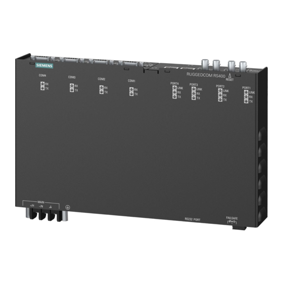
Introduction 1.2 Description • CSA/UL 60950 safety approved to 85 °C (185 °F) Description The RUGGEDCOM RS400F features various ports, controls and indicator LEDs on the front panel for connecting, configuring and troubleshooting the device. POWER LED ALARM LED RESET Button Ethernet Port Status LEDs Serial Port Status LEDs Failsafe Alarm Relay... -
Page 13: Required Tools And Materials
Introduction 1.3 Required Tools and Materials RESET Button Shuts down and restarts the device. Ethernet Port Status LEDs Indicate the status of the associated Ethernet port. State Meaning LINK Solid Link established Blinking Link activity No link detected Blinking Link activity (receive) No link activity Blinking... -
Page 14: Decommissioning And Disposal
Siemens also does not recommend using copper Ethernet ports to interface with devices in the field across distances that could produce high levels of ground potential rise (i.e. greater than 2500 V), during line-to-ground fault conditions. - Page 15 Introduction 1.5.2 Supported Fiber Optic Cables Cable Type Wavelength (nm) Modal Bandwidth Distance (m) (MHz·km) 100Base-FX 1000Base-SX 10GBase-SR OM1 (62.5/125) — 1300 2000 — — OM2 (50/125) — 1300 2000 — — OM3 (50/125) 1500 — 1300 2000 — — OM4 (50/125) 3500 —...
-
Page 16: Installing The Device
This product contains no user-serviceable parts. Attempted service by unauthorized personnel shall render all warranties null and void. Changes or modifications not expressly approved by Siemens Canada Ltd. could invalidate specifications, test results, and agency approvals, and void the user's authority to operate the equipment. -
Page 17: General Procedure
Inspect the package for damage before opening it. Visually inspect each item in the package for any physical damage. Verify all items are included. Note If any item is missing or damaged, contact Siemens for assistance. RUGGEDCOM RS400F Installation Manual, 11/2022, C79000-G8976-1341-06... -
Page 18: Mounting The Device
Installing the Device 2.3 Mounting the Device Mounting the Device The RUGGEDCOM RS400F is designed for maximum mounting and display flexibility. It can be equipped with connectors that allow it to be installed in a rack, on a DIN rail, or directly on a panel. NOTICE Heat generated by the device is channeled outwards from the enclosure. -
Page 19: Mounting The Device To A Rack
Installing the Device 2.3.2 Mounting the Device to a Rack Screw Figure 2.1 Mounting the Device to a DIN Rail Install one of the supplied #8-32 lock screws on either side of the device to secure the adapters to the DIN rails. Removing the Device To remove the device from a DIN rail, do the following: Loosen or remove the #8-32 lock screws on both sides of the device. -
Page 20: Mounting The Device To A Panel
Installing the Device 2.3.3 Mounting the Device to a Panel Make sure the rack mount adapters are installed on the correct side of the chassis. Note The chassis features multiple mounting holes, allowing the rack mount adapters to be installed up to 25 mm (1 in) from the face of the device. Rear Front Rack Mount Adaptor... -
Page 21: Connecting The Failsafe Alarm Relay
Installing the Device 2.4 Connecting the Failsafe Alarm Relay Screw Panel/DIN Rail Adaptor Figure 2.4 Panel Mounting Secure the device to the panel using four #6-32 screws. Connecting the Failsafe Alarm Relay The failsafe relay can be configured to latch based on alarm conditions. The NO (Normally Open) contact is closed when the unit is powered and there are no active alarms. -
Page 22: Grounding The Device
Installing the Device 2.5 Grounding the Device Figure 2.5 Failsafe Alarm Relay Wiring Grounding the Device The RUGGEDCOM RS400F chassis ground terminal uses a #6-32 screw. It is recommended to terminate the ground connection with a #6 ring lug and torque it to 1.7 N·m (15 lbf·in). -
Page 23: Connecting Ac Power
Installing the Device 2.6.1 Connecting AC Power • For 100-240 VAC rated equipment, an appropriately rated circuit breaker must be installed. • Use only #16 gage copper wiring when connecting terminal blocks. • A circuit breaker is not required for 12, 24 or 48 VDC rated equipment. •... -
Page 24: Connecting Dc Power
Installing the Device 2.6.2 Connecting DC Power Connect the negative wire from the power source to the negative/neutral (-/N) terminal on the terminal block. Using a braided wire or other appropriate grounding wire, connect the surge ground terminal to the chassis ground connection. The surge ground terminal is used as the ground conductor for all surge and transient suppression circuitry internal to the unit. - Page 25 Installing the Device 2.6.2 Connecting DC Power Connect the negative wire from the power source to the negative/neutral (-/N) on the terminal block. Using a braided wire or other appropriate grounding wire, connect the surge ground terminal to the chassis ground connection. The surge ground terminal is used as the ground conductor for all surge and transient suppression circuitry internal to the unit.
-
Page 26: Device Management
Device Management This section describes how to connect to and manage the device. Connecting to the Device The following describes the various methods for accessing the RUGGEDCOM RS400F console and Web interfaces on the device. For more detailed instructions, refer to the "RUGGEDCOM ROS Configuration Manual"... -
Page 27: Configuring The Device
Device Management 3.2 Configuring the Device IP address. For more information about available ports, refer to "Communication Ports" (Page 19). Configuring the Device Once the device is installed and connected to the network, it must be configured. All configuration management is done via the RUGGEDCOM ROS interface. For more information about configuring the device, refer to the "RUGGEDCOM ROS Configuration Manual"... -
Page 28: Communication Ports
Communication Ports The RUGGEDCOM RS400F can be equipped with various types of communication ports to enhance its abilities and performance. To determine which ports are equipped on the device, refer to the factory data file available through RUGGEDCOM RS400F. For more information on how to access the factory data file, refer to the "RUGGEDCOM ROS Configuration Manual"... -
Page 29: Fiber Optic Ethernet Ports
Communication Ports 4.2 Fiber Optic Ethernet Ports WARNING Electric shock hazard – risk of serious personal injury and/or equipment interference If shielded cables are used, make sure the shielded cables do not form a ground loop via the shield wire and the RJ45 receptacles at either end. Ground loops can cause excessive noise and interference, but more importantly, create a potential shock hazard that can result in serious injury. -
Page 30: Modem Port
Communication Ports 4.3 Modem Port (Straight Tip) connectors. Make sure the Transmit (Tx) and Receive (Rx) connections of each port are properly connected and matched to establish a proper link. Port Types Tx Connector Tx Connector Rx Connector Rx Connector Figure 4.4 LC Port Figure 4.3... -
Page 31: Serial Ports
Communication Ports 4.4 Serial Ports The modem card is equipped with a standard RJ11 telephone port. The following is the pin-out description for the RJ11 port: Description Reserved (Do Not Connect) Reserved (Do Not Connect) Ring Figure 4.7 RJ11 Port Pin Configuration Reserved (Do Not Connect) Reserved (Do... -
Page 32: Serial Rs232/Rs485/Rs422 Db9 Ports
Communication Ports 4.4.2 Serial RS232/RS485/RS422 DB9 Ports communicating with an another DCE device, such as another RUGGEDCOM RS400F, the RX and TX pins must be crossed-over using, for example, a NULL modem cable. The following is the pin-out description for the RS232 DB9 ports: ... -
Page 33: Serial Rs232/Rs485/Rs422 Rj45 Ports
Communication Ports 4.4.3 Serial RS232/RS485/RS422 RJ45 Ports 4.4.3 Serial RS232/RS485/RS422 RJ45 Ports The RUGGEDCOM RS400F can be equipped with serial RS232/RS485/RS422 RJ45 ports. Each port can be set individually through the RUGGEDCOM RS400F operating system to operate in RS232, RS485 or RS422 mode. For more information, refer to the "RUGGEDCOM ROS Configuration Manual"... -
Page 34: Connecting Multiple Rs485 Devices
Communication Ports 4.4.5 Connecting Multiple RS485 Devices The following is the pin-out description for the RS485 insulated terminals: Terminal Description Positive Negative Common (Isolated Ground) Figure 4.11 Serial Insulated Terminal Port 4.4.5 Connecting Multiple RS485 Devices Each RS485 port can communicate with multiple RS485 devices by wiring devices together in sequence over a single twisted pair with transmit and receive signals on the same two wires (half duplex). - Page 35 Communication Ports 4.4.5 Connecting Multiple RS485 Devices 120Ω 10nF 120Ω 10nF RUGGEDCOM RS400F Common (Isolated Ground) Negative Positive Shield to Earth (Connected At a Single Point) RS485 Devices (32 Total) Figure 4.12 Recommended RS485 Wiring RUGGEDCOM RS400F Installation Manual, 11/2022, C79000-G8976-1341-06...
-
Page 36: Technical Specifications
Technical Specifications This section details the specifications and operating conditions of the device. Power Supply Specifications Power Internal Maximum Power Minimum Input Maximum Input Supply Type Fuse Rating Consumption 12-24 VDC 10 VDC 36 VDC 6.3 A(F) 48 VDC 36 VDC 59 VDC 2 A(T) HI (125/250 VDC) -
Page 37: Fiber Optic Ethernet Port Specifications
To convert from average to peak, add 3 dBm. To convert from peak to average, subtract 3 dBm. Maximum segment length is greatly dependent on factors such as fiber quality, and the number of patches and splices. Consult a Siemens sales associate when determining maximum segment distances. -
Page 38: Serial Port Specifications
Technical Specifications 5.5 Serial Port Specifications Serial Port Specifications Port Type Media Distance Connector Type RS232 Standard RS232 15 m (49 ft) Shielded Serial Cable RS485 Shielded Twisted-Pair 1200 m (3937 ft) Insulated Terminals RS232/RS485/RS422 Shielded Twisted-Pair 1200 m (3937 ft) RS232/RS485/RS422 Shielded Twisted-Pair 1200 m (3937 ft) - Page 39 Technical Specifications 5.8 Dimension Drawings 44.2 291.3 25.4 Figure 5.1 Overall Dimensions 34.5 22.9 466.6 11.4 481.3 Figure 5.2 Rack Mount Dimensions RUGGEDCOM RS400F Installation Manual, 11/2022, C79000-G8976-1341-06...
- Page 40 Technical Specifications 5.8 Dimension Drawings 335.0 324.9 Figure 5.3 Panel and Din Rail Mount Dimensions RUGGEDCOM RS400F Installation Manual, 11/2022, C79000-G8976-1341-06...
- Page 41 Technical Specifications 5.8 Dimension Drawings RUGGEDCOM RS400F Installation Manual, 11/2022, C79000-G8976-1341-06...
-
Page 42: Certification
Approvals This section details the standards to which the RUGGEDCOM RS400F complies. Note All relevant certificates and test reports are available on Siemens Industry Online Support [https://support.industry.siemens.com]. 6.1.1 UKCA This device is certified for use in Great Britain and bears the United Kingdom Certified Assessed (UKCA) marking. -
Page 43: European Union (Eu)
Certification 6.1.3 European Union (EU) 6.1.3 European Union (EU) This device is declared by Siemens Canada Ltd. to comply with essential requirements and other relevant provisions of the following EU directives: • EN 62368-1 Information Technology Equipment – Safety – Part 1: General Requirements •... -
Page 44: Fda/Cdrh
Title 21 Code of Federal Regulations (CFR) – Chapter I – Sub-chapter J – Radiological Health 6.1.6 ISED This device is declared by Siemens Canada Ltd. to meet the requirements of the following ISED (Innovation Science and Economic Development Canada) standard: • CAN ICES-3 (A)/NMB-3 (A) 6.1.7... -
Page 45: Emc And Environmental Type Tests
Certification 6.2 EMC and Environmental Type Tests • IEC 61000-6-2 Electromagnetic Compatibility (EMC) – Part 6-2: Generic Standards – Immunity for Industrial Environments EMC and Environmental Type Tests The RUGGEDCOM RS400F has passed the following EMC and environmental tests. IEC 61850-3 EMC Type Tests Test Description Test Levels... - Page 46 Certification 6.2 EMC and Environmental Type Tests Test Description Test Levels Severity Levels IEC 61000-4-16 Mains Frequency Signal Ports 30 V Continuous, 300 V for 1 s Voltage DC Power Ports 30 V Continuous, 300 V for 1 s IEC 61000-4-17 Ripple on DC DC Power Ports Power Supply...
- Page 47 Certification 6.2 EMC and Environmental Type Tests Test Description Test Levels IEC 60068-2-2 Dry Heat Test Bd 85 °C (185 °F), 16 Hours IEC 60068-2-30 Humidity (Damp Test Db 95% (non-condensing), Heat, Cyclic) 55 °C (131 °F), 6 cycles IEC 60255-21-1 Vibration 2 g at 10-150 Hz IEC 60255-21-2...
- Page 48 For more information Siemens RUGGEDCOM https://www.siemens.com/ruggedcom Industry Online Support (service and support) https://support.industry.siemens.com Industry Mall https://mall.industry.siemens.com Siemens Canada Ltd. Digital Industries Process Automation 300 Applewood Crescent Concord, Ontario, L4K 4E5 Canada © 2022 Siemens Canada Ltd. Subject to change...
Need help?
Do you have a question about the SIMATIC NET RUGGEDCOM RS400F and is the answer not in the manual?
Questions and answers