Table of Contents
Advertisement
For PC (Windows 10/11)
User Manual
Carefully read the instructions provided in this
manual before installing the product, before any use
of the product and before any maintenance. Be sure
to follow the safety instructions. Failure to follow these
instructions may result in accidents and/or damage.
Keep this manual so that you can refer to the
instructions in the future.
Advertisement
Table of Contents

Related Manuals for Thrustmaster T818


Summary of Contents for Thrustmaster T818
- Page 1 For PC (Windows 10/11) User Manual Carefully read the instructions provided in this manual before installing the product, before any use of the product and before any maintenance. Be sure to follow the safety instructions. Failure to follow these instructions may result in accidents and/or damage. Keep this manual so that you can refer to the instructions in the future.
-
Page 2: Table Of Contents
........20 Installation using the Desk Mounting Kit* ........23 Installation using the Cockpit Mounting Kit* ........ 30 INSTALLING A THRUSTMASTER WHEEL RIM USING THE QUICK RELEASE ADAPTER* .... 39 Installing the Quick Release Adapter on the T818 base ..........41... - Page 3 CHANGING THE SIDE PLATES ....50 T818 HARDWARE CONTROL PANEL ..51 Turning off the base’s Force Feedback ... 52 Turning Force Feedback on the base back on ............54 INSTALLATION ON PC ....... 55 10. PEDAL SET* MODE ........61 Pedal set position ........
- Page 4 This manual will help you install and use your T818 base under the best conditions. Before getting started racing, carefully read the instructions and the warnings: they will help you get the most...
- Page 5 Updating the firmware In order for the T818 base to function properly with video games, it is essential that the firmware be updated. carry update, visit https://support.thrustmaster.com/product/t818. Select Firmware and follow the instructions, including the downloading and installation procedure.
-
Page 6: Box Contents
Box contents... -
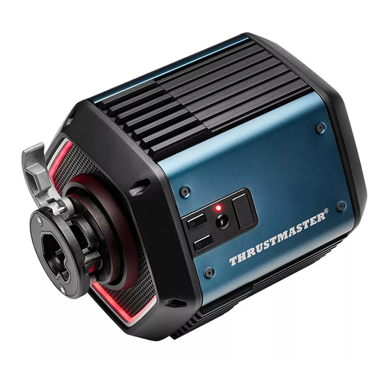
Page 7: Features Of The Base
Features of the base ❶ On/off button ❷ Power port ❸ Connection port to computer ❹ Unused port – Function available soon ❺ Connection port to pedal set ❻ Unused port – Function available soon... - Page 8 ❼ Fast release wheel attachment system ❽ Base’s buttons and LED ❾ Hexagon of RGB LEDs...
-
Page 9: General Information
- Keep the product away from animals and insects. - This product is intended for domestic and interior use only. - Do not use the T818 base and the power supply in the event of visible damage or a malfunction (for example, after a shock). -
Page 10: Information Regarding Use
4. Information regarding use of the base Documentation Before using this product, carefully read this documentation again, and keep it for future reference. - Page 11 Electrical shock - Keep the product in a dry location and do not expose it to dust or sunlight. - Do not twist or pull on the connectors and cables. - Do not spill any liquid on the product or its connectors. - Do not short-circuit the product.
- Page 12 - If you will not be using the base for an extended period of time or if you will be away from the base, power off the base and unplug its power supply cable from the wall outlet. - The wall outlet must have been installed according to proper electrical trade practices by a specialist.
- Page 13 Power supply - Only use the power supply indicated in the user manual. - Only use the power supply with the network voltage and frequency indicated on the power supply’s rating plate. Securing the gaming area - Do not place any object in the gaming area which may disrupt the practice of the user, or which may provoke an inappropriate movement or an interruption by another person (coffee cup, telephone, keys, for...
- Page 14 Information regarding the power supply Published Value Unit information Manufacturer’s GUILLEMOT name or CORPORATION S.A. trademark 414 196 758 Rennes Business Place du Granier number BP 97143 Address 35571 Chantepie Cedex France Model identifier A1801-2407 Input voltage 100 – 240 Input AC 50 –...
- Page 15 Air vents Make sure not to block any of the air vents on the base. For optimal ventilation, make sure to do the following: - Position the base at least 10 cm away from any wall surfaces. - Do not place the base in any tight spaces. - Do not cover the base.
- Page 16 In the event of intensive use, you may notice a slight odor emanating from the base. This specific case mainly occurs with new products: it is normal, and subsides over time.
- Page 17 Injuries due to Force Feedback and repeated movements Using a Force Feedback racing wheel may cause muscle or joint pain. To avoid any problems: - Warm up beforehand, and avoid lengthy periods of practice. - Take a 10 to 15-minute break after each hour of practice.
- Page 18 - Make sure that the base and the wheel are properly attached, as per this manual’s instructions. Risk of unforeseen, powerful and rapid rotations: never place a hand or an arm through the openings in the wheel rim, or in the wheel’s trajectory of rotation.
-
Page 19: Installation On A Support
5. Installation on a support A complete diagram of the base is available at https://support.thrustmaster.com/product/t818. Before each use, verify that the base is still properly attached to the support, as per this manual’s instructions. -
Page 20: Installation Without An Additional
Installation without additional mounting system *Screws not included... - Page 21 It is possible to install the T818 base on different types of supports. Keep in mind that the T818 base features powerful Force Feedback, and therefore must be solidly attached. Attach the base to your support using four appropriate screws (not included), so as not to damage the base.
- Page 22 Dimensions of the base (in mm) diagram base available https://support.thrustmaster.com/product/t818. You can print out the diagram and use it on your support in order to determine and prepare the locations for the screws.
-
Page 23: Installation Using The
Installation using the Desk Mounting Kit* *Sold separately The Desk Mounting Kit is a system for mounting the T818 base on tables and desks, composed of a support plate, two brackets and a set of screws with nuts. - Page 24 Mounting diagram on tables and desks A mounting diagram on tables and desks is available at https://support.thrustmaster.com/product/t818. You can print out the diagram and use it on your support in order to determine and prepare the locations for the screws.
- Page 25 Installation procedure - Position the mounting plate underneath the base, lining up the perforations. - Tighten the four mounting screws clockwise. - Insert the brackets on each side. Make sure that they are properly positioned.
- Page 26 - Tighten the two clamping screws.
- Page 27 2.5 and 4 cm, for the base to be used under the best conditions. T818 must be used on a table or desk made of a solid material (i.e. MDF or wood), without...
- Page 28 Option: mounting in a cockpit The Desk Mounting Kit can also be installed in a cockpit, if the cockpit’s shelf can be tilted. Use these screws included with the Desk Mounting Kit to attach the base to the cockpit’s shelf. Three configurations of screws are possible, depending on your cockpit.
-
Page 30: Installation Using The
Installation using the Cockpit Mounting Kit* *Sold separately The Cockpit Mounting Kit is a system for mounting the T818 base in cockpits, composed of a support plate and a set of screws with nuts. - Page 31 You can print out the diagram and use it in your cockpit in order to verify your cockpit’s compatibility. Most cockpits available on the market are already compatible with Thrustmaster bases (TS-PC Racer Servo Base, TS-XW Servo Base, T-GT II Racing Wheel Servo Base, T300 Racing Wheel Servo Base).
- Page 32 Only use the mounting systems and accessories specified by the manufacturer.
- Page 33 Installation procedure - Assemble the Cockpit Mounting Kit on the T818 base. - Tighten the four mounting screws clockwise.
- Page 34 - Position the T818 base with the Cockpit Mounting Kit on the cockpit’s shelf, lining up the perforations.
- Page 35 - Screw in the four mounting screws clockwise.
- Page 36 Set of screws Use these screws included with the Cockpit Mounting Kit to attach the base to the cockpit’s shelf. Three configurations of screws are possible, depending on your cockpit.
- Page 37 Stability Do not mount the base with the Cockpit Mounting Kit on the front edge or rear edge of the shelf. Everything must fully rest on the shelf, and be screwed into the shelf.
- Page 38 Getting into and out of the cockpit Do not use the wheel’s rim as a lever to help you get into or out of your racing seat: by doing so, you risk damaging your base and/or your wheel.
-
Page 39: Installing A Thrustmaster Wheel Rim
6. Installing a Thrustmaster wheel rim using the Quick Release Adapter* *Included with the T818 base. Also sold separately. The Quick Release Adapter is an adapter that makes the T818 base’s fast release system compatible with the ecosystem of Thrustmaster wheel rims launched prior to... - Page 40 Manipulate the Quick Release Adapter with care. It is equipped with pins which, in the event that they are damaged, will render the wheel unusable.
-
Page 41: Installing The Quick Release Adapter On
Installing the Quick Release Adapter on the T818 base Power off the base using the On/off button ❶ before attaching a wheel rim or changing a wheel rim. *Wheel rim sold separately... - Page 42 Mounting procedure - Insert the adapter in the wheel rim’s connector. Be sure to respect the insertion direction, so as not to damage the connectors. Use the arrows below to help guide you.
- Page 43 - Insert the clamp ring in the adapter. Fully tighten the ring.
- Page 44 If your wheel is not detected in the Control Panel or does not work in games, it is possible that the clamp ring has not been fully tightened.
- Page 45 - Tighten the screw using an appropriate cross-headed (i.e. Phillips head) screwdriver (not included).
- Page 46 - Insert the wheel into the base. Make sure that the locking lever is in the open position.
- Page 47 - Lower the locking lever. Pinch hazard Do not leave your finger in the locking system when lowering the lever. Before each use, verify that the base is still properly attached to the support, as per this manual’s instructions.
- Page 48 Dismounting procedure Carry out the dismounting procedure by reversing the mounting procedure steps, as shown below.
- Page 49 It may be necessary to use a tool (a screwdriver or equivalent — not included) to act as a lever and remove the adapter, if the adapter cannot be removed by hand.
-
Page 50: Changing The Side Plates
Changing the side plates You can customize the look of your T818 base thanks to interchangeable metal plates (sold separately), available in a variety of colors. - Unscrew the four screws on each side of the base using a 2 mm Allen key (not included) in order to remove the plates. -
Page 51: T818 Hardware Control Panel
T818 hardware control panel ❾ / ❿ Action buttons 22 and 23 ⓫ LED ⓬ Multifunctional Mode button ⓭ Button to turn off Force Feedback... -
Page 52: Turning Off The Base's Force Feedback
Turning off the base’s Force Feedback Feedback at any time thanks to the dedicated button ⓭. For any reason, it is possible to turn off the base’s Force - Press the button to turn off Force Feedback ⓭ once. The LED ⓫ and the hexagon of RGB LEDs ❾ on the front face flash red. - Page 53 Should you feel any pain or discomfort, slide your thumbs towards the exterior of the wheel rim while your palms remain against the wheel rim and your other fingers grip the wheel, then quickly release your the button to turn off Force Feedback ⓭ while making fingers and completely let go of the wheel.
-
Page 54: Turning Force Feedback On The Base
Turning Force Feedback on the base back on If you have turned off the Force Feedback on the base and want to experience Force Feedback effects again, using the On/off button ❶. you must power off the base and then power it back on If the Force Feedback effects are still disabled, restart the video game. -
Page 55: Installation On Pc
Force Feedback software for PC. Click Racing Wheels / T818, and then click Drivers. Your wheel’s firmware version appears in the upper right-hand side, in the tabs of the T818’s software... - Page 57 ❶ Install the wheel rim on the base (for more 6. Installing a information, please refer to section Thrustmaster wheel rim using the Quick Release ❷ Connect the pedal set (not included) to the RJ12 Adapter). ❸ Plug the power adapter into an electrical outlet.
- Page 58 - Select Start / Thrustmaster / FFB Racing Wheel / Control Panel to open the Game Controllers window. The Game Controllers window displays the racing wheel name Thrustmaster Advanced Mode Racer, along with OK status. - Click Properties to configure your racing wheel in the T818’s software Control Panel:...
- Page 59 • Gain Settings tab: lets you adjust the power of Force Feedback effects in your PC games, as well as adjust the LEDs. By unlocking the lock, you can: - increase the Master Gain forces up to 100%, - decrease the Damper forces down to 0%, - access Performance mode and Extreme mode.
- Page 60 - Do not set Force Feedback to a level that is too high in relation to your expertise and your physical condition. Use the button to turn off Force Feedback, if necessary. - Do not overestimate your expertise: in real life, even the best race drivers cannot avoid all accidents and, in racing simulation, each video game uses different Force Feedback effects.
-
Page 61: Pedal Set* Mode
10. Pedal set* mode *Sold separately the LED ⓫ indicates the mode — position and type — Each time the base restarts (and after it self-calibrates), in which your pedal set is configured. -
Page 62: Pedal Set Position
Pedal set position The pedal set features two different positions: normal and inverted. The normal position corresponds to the default position (clutch on the left / accelerator on the right). In the inverted position, the accelerator and clutch pedals are inverted (accelerator on the left / clutch on the right): this position is only possible with a 3-pedal pedal set. - Page 63 Switching from normal position to inverted position (and vice versa) - Press and hold down the Mode button ⓬ for four seconds. Steady red LED = normal position Steady green LED = inverted position...
-
Page 64: Pedal Set Type
Pedal set type Two types of pedal sets are detected by the T818 base: T2PM-T3PA-T3PM without Load Cell technology (default type), and T-LCM with Load Cell technology. The default type (T2PM-T3PA-T3P) is saved in the wheel base’s internal memory and always remains active, apart from if you connect a T-LCM pedal set to the RJ12 port, or if you manually make a switch. - Page 65 Switching from T2PM-T3PA-T3PM type to T- LCM type (and vice versa) ⓬ and the left paddle shifter (–) for 5 seconds. - Simultaneously press and hold down the Mode button The LED flashes 1 time = T2PM-T3PA-T3PM type The LED flashes 10 times = T-LCM type...
- Page 66 If you are using a T2PM, T3PA or T3PM pedal set in T-LCM type, this pedal set will not function properly: the pedals’ values will no longer reach 100%. In order for the pedal set to function properly again (and reach the 100% values), you must manually switch the base’s mode to T2PM-T3PA-T3PM type.
-
Page 67: Manually Changing The Angle Of
11. Manually changing the angle of rotation via the wheel The T818 base features an angle of rotation adjustable between 270° and 1080°. In many video games, the wheel’s angle of rotation is automatic and adjusts on its own according to the car being used in the game. - Page 68 Procedure for changing the angle of rotation Manually changing the angle of rotation is only possible when a video game is active. - Simultaneously press the Mode button ⓬ and the right directional button on the wheel to increase the angle of rotation by one level;...
- Page 69 5 possible levels Angle of rotation Flashing of the LED 270° 360° 540° 900° 1080°...
- Page 70 The angle of rotation modified manually via the wheel is not permanently saved. This procedure must be carried out each time the video game or the base restarts.
-
Page 71: Faq And Technical Support
12. FAQ and technical support Do you have questions regarding the T818 base, or are you experiencing technical problems? If so, visit the Thrustmaster technical support website: https://support.thrustmaster.com/product/t818.
Need help?
Do you have a question about the T818 and is the answer not in the manual?
Questions and answers