Advertisement
Quick Links
Advertisement

Subscribe to Our Youtube Channel
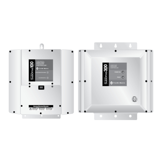
Summary of Contents for Franklin Electric SubDrive NEMA 4
- Page 1 SubDrive Tank Drawdown Installation Instruction Manual 225770901...
- Page 2 400 E. Spring Street Bluffton, IN 46714 Tel: 260-824-2900 • Fax: 260-824-2909 www.franklin-electric.com 225767101 Rev. 2 M1617 10-10...
- Page 3 TANK DRAWDOWN INSTALLATION INSTRUCTION MANUAL...
- Page 4 TANK DRAWDOWN INSTALLATION INSTRUCTION MANUAL...
-
Page 5: Tools And Hardware Required
¼" quick connects that will attach the aux device to the relay interface. For the SubDrive Nema 4 units, excluding the SubDrive300, an Auxiliary Relay Board is required. An Auxiliary Relay Board kit can be purchased with order number 225755901. - Page 6 TANK DRAWDOWN INSTALLATION INSTRUCTION MANUAL SubDrive Nema 4 Installation Procedure (For SubDrive300 see pg 6) 1. If the SubDrive is powered, remove power from the drive and wait at least 10 minutes before accessing the drive to ensure that the bus voltage has been given suffi cient time to dissipate.
- Page 7 TANK DRAWDOWN INSTALLATION INSTRUCTION MANUAL 4. Add a second 25 to 80 psi sensor to the system. The pressure setting on the additional sensor will need to be set below the regulating sensor, but above the tank pre-charge pressure. The pressure can be adjusted once the system is up and running. 5.
- Page 8 TANK DRAWDOWN INSTALLATION INSTRUCTION MANUAL 7. Connect the green wire to the pressure sensor (J11) terminal at the SubDrive. Connect the white wire to the piggyback connector at J11. 8. Connect the Jumper wire to the pressure sensor (J11) terminal and to the Common (COM) terminal of the Auxiliary Relay Board.
- Page 9 The pressure setting on the additional sensor will need to be set below the regulating sensor, but above the tank pre-charge pressure. Relay Pressure Sensor Jumper Figure 1: SubDrive NEMA 4 Wiring White Green Black Low Cut-in Sensor Regulating Sensor...
- Page 10 TANK DRAWDOWN INSTALLATION INSTRUCTION MANUAL SubDrive300 Installation Procedures 1. If the SubDrive is powered, remove power from the drive and wait at least 10 minutes before accessing the drive to ensure that the bus voltage has been given sufficient time to dissipate. 2.
- Page 11 TANK DRAWDOWN INSTALLATION INSTRUCTION MANUAL 6. Connect the green wire to the pressure sensor (J12) terminal at the SubDrive. Connect the white wire to the piggyback connector at J12. 7. Connect the Jumper wire to the pressure sensor (J11) terminal and to the Common (COM) terminal.
- Page 12 TANK DRAWDOWN INSTALLATION INSTRUCTION MANUAL 8. Connect the black wire from the cut-in pressure switch to the Normally Closed (NC) terminal on the Auxiliary Relay Board. Connect the Red wire from the regulating pressure switch to the Normally Open (NO) terminal on the Auxiliary Relay Board.
- Page 13 TANK DRAWDOWN INSTALLATION INSTRUCTION MANUAL 10. Re-attach the access cover. 11. Re-apply power. 12. Adjust the pressure setting on the low pressure cut-in switch for the appropriate off time. The pressure setting on the additional sensor will need to be set below the regulating sensor, but above the tank pre-charge pressure.
- Page 14 TANK DRAWDOWN INSTALLATION INSTRUCTION MANUAL Pressure Relay Shut-O Sensor Jumper Orange Black Green Blue Low Cut-in Sensor Regulating Sensor Overpressure Sensor Figure 2: SubDrive300 Wiring...
- Page 15 TANK DRAWDOWN INSTALLATION INSTRUCTION MANUAL Notes:...
- Page 16 TANK DRAWDOWN INSTALLATION INSTRUCTION MANUAL Notes:...


Need help?
Do you have a question about the SubDrive NEMA 4 and is the answer not in the manual?
Questions and answers