Table of Contents
Advertisement
Quick Links
Before any procedure of installation, handling
or start of the pump, read the instructions
contained in this manual carefully. Follow step
by step the rules for the correct assembly of
the components and observe the provisions
of the country of use concerning the best
practice of the state of the art.
1. GENERAL DATA
1.1 General description
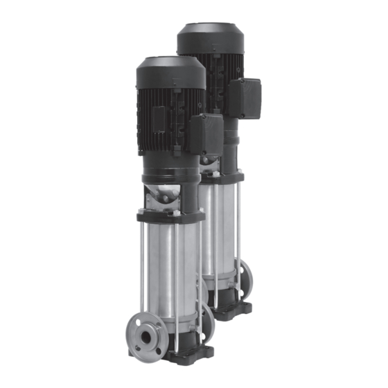
VR pumps are vertical multistage centrifugal pumps.
Models 3VR, 5VR and 9VR operate with clockwise
rotation when observed from above. Models 16VR
operate counter-clockwise when observed from above.
(Exceptions can exist in high pressure assemblies where
one of the two pumps has operation and hydraulics
inverted.) These pumps are not self-priming. Pump
intake and discharge are located on the same axis, at
the bottom of the pump. A standard mechanical seal in
the shaft inlet provides separation of the electric motor
from the pumped product. Mounting dimensions can be
found on the dimensions table, page 5.
1.2 Flanges available:
F- Round flanges on body type PN25: the pump is
supplied with joints, bolts and counterflanges.
T- Oval flanges on body type PN16: the pump is supplied
with oval counterflanges for pipe to be screwed, joints
and bolts (Optional accessories).
VR Series-
Vertical Multistage Pump
OWNER'S MANUAL
V- Connections with rapid fittings type "VICTAULIC":
the pump is supplied with the collars(Optional
accessories).
C- Connections with round fittings type CLAMP -
FlexiClamp: the pump is supplied without collars
(Optional accessories).
1.3 Applications
VR centrifugal multi-stage pumps are suitable for a wide
range of applications. They can be used in agriculture
as well as in the civil and industrial field, as for example:
water tank, watering, irrigation, high pressure washing,
fire fighting protection, air conditioning, etc.
1.4 Pumped liquids
Clean liquids, compatible with the construction materials
of the pump, not containing solid particles or fibres.
If the pump is used to pump liquids with viscosity or a
density higher than water ones, it is necessary to use a
motor with a proportionally greater power.
1.5 Temperature of pumped liquids
The pumped liquids must remain within a given
temperature range: - 20 ºC to + 120 ºC
2 DELIVERY AND STORAGE
2.1 Delivery
The pumps are supplied in their original package
in which they must remain until they are installed.
Pay attention not to subject the pump to flexing after
unpackaged: this may cause the misalignment or the
damaging of the pump itself. Take care not to bump or
bind the components.
2.2 Storage and Handling
Storage temperature:
Pump: - 20 ºC to + 60 ºC
Neither the pump, nor the motor should be exposed
to sunlight. If the pump was not packaged, it has
to be stored in the warehouse vertically, in order to
prevent any possible misalignment. The pump must be
protected against frost and atmospheric agents. During
storage, the pump can be supported as shown in figure
2.1. In case of lack of the motor use a belt wrapped on
the pump head, paying utmost care not to damage the
lateral joint covering protections.
The motors of the pumps supplied with
eyebolts must not be used to handle the
whole assembled electropump (see fig. 2.2).
Advertisement
Table of Contents

Subscribe to Our Youtube Channel
Related Manuals for Franklin Electric VR Series


Summary of Contents for Franklin Electric VR Series
- Page 1 VR Series- Vertical Multistage Pump OWNER'S MANUAL V- Connections with rapid fittings type “VICTAULIC”: the pump is supplied with the collars(Optional accessories). C- Connections with round fittings type CLAMP - FlexiClamp: the pump is supplied without collars (Optional accessories). 1.3 Applications VR centrifugal multi-stage pumps are suitable for a wide range of applications.
-
Page 2: Installation And Preparation
There can be two relevant application cases: 3 INSTALLATION AND PREPARATION - Case shown in fig. 1.A: Pump under pressure, which 3.1 Ambient temperature both from a tank as shown in figure and from civil Maximum: + 40 ºC. waterworks system, shall allow the plant to foresee a protection against water lack (see fig. -
Page 3: Maintenance
Reassemble the joint covering carter and re-tighten you are in a safety position during this operation. Close the screws of the motor at the end of the above the gate valve after the outcome of a constant liquid flow mentioned procedure. from the cap before closing it again in order to avoid the contact with the liquid. -
Page 4: Troubleshooting Table
7 TROUBLESHOOTING TABLE Before any intervention, disconnect the pump from power supply. If the pump is used for hazardous liquids for human beings, inform compulsorily the per- sonnel performing the repairing. In this case, clean the pump, in order to assure the safety of the operator. - Page 6 Fig. 1...
- Page 7 Fig. 2 Fig. 3...
-
Page 8: Limited Warranty
LIMITED WARRANTY Franklin Electric Co., Inc. Franklin Electric Co., Inc. warrants its new products to be free of defects in material and workmanship for a period of 1 year from date of installation or 2 years from date of manufacture, whichever comes fi rst, WHEN installed in clean, potable water applications. Warranty does not cover applications pumping saltwater or other corrosive liquids.
Need help?
Do you have a question about the VR Series and is the answer not in the manual?
Questions and answers