Table of Contents
Advertisement
Quick Links
ControlLogix EtherNet/IP Communication
Module
Catalog Numbers 1756-EN2TR, 1756-EN3TR
Topic
Important User Information
Environment and Enclosure
Prevent Electrostatic Discharge
North American Hazardous Location Approval
About the Module
Before You Begin
Install the Module
Status Indicators
Specifications
Additional Resources
Installation Instructions
Page
2
3
5
4
5
7
11
19
21
25
Advertisement
Table of Contents

Subscribe to Our Youtube Channel
Related Manuals for Rockwell Automation ControlLogix 1756-EN2TR


Summary of Contents for Rockwell Automation ControlLogix 1756-EN2TR
- Page 1 Installation Instructions ControlLogix EtherNet/IP Communication Module Catalog Numbers 1756-EN2TR, 1756-EN3TR Topic Page Important User Information Environment and Enclosure Prevent Electrostatic Discharge North American Hazardous Location Approval About the Module Before You Begin Install the Module Status Indicators Specifications Additional Resources...
-
Page 2: Important User Information
In no event will Rockwell Automation, Inc. be responsible or liable for indirect or consequential damages resulting from the use or application of this equipment. -
Page 3: Environment And Enclosure
Environment and Enclosure This equipment is intended for use in a Pollution Degree 2 industrial ATTENTION environment, in overvoltage Category II applications (as defined in IEC 60664-1), at altitudes up to 2000 m (6562 ft) without derating. This equipment is considered Group 1, Class A industrial equipment according to IEC/CISPR 11. -
Page 4: North American Hazardous Location Approval
North American Hazardous Location Approval The following information applies when Informations sur l’utilisation de cet operating this equipment in hazardous équipement en environnements dangereux. locations. Products marked "CL I, DIV 2, GP A, B, C, D" are suitable for Les produits marqués "CL I, DIV 2, GP A, B, C, D" ne use in Class I Division 2 Groups A, B, C, D, Hazardous conviennent qu'à... -
Page 5: Prevent Electrostatic Discharge
Prevent Electrostatic Discharge This equipment is sensitive to electrostatic discharge, which can ATTENTION cause internal damage and affect normal operation. Follow these guidelines when you handle this equipment: • Touch a grounded object to discharge potential static. • Wear an approved grounding wriststrap. •... -
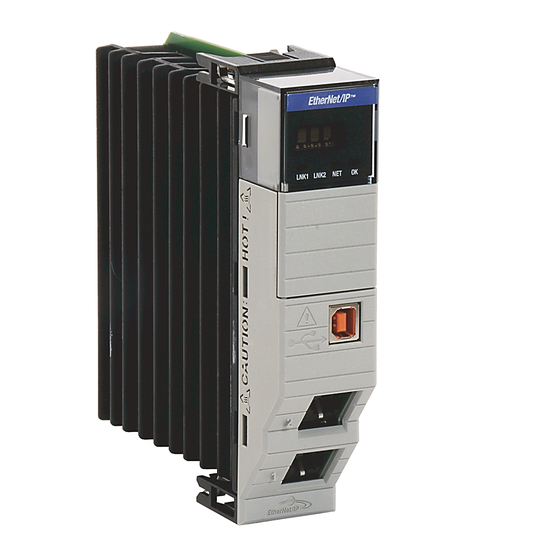
Page 6: Item Description
Use this figure to identify the external features of the module. EtherNet/IP 10/100 BASE T LNK1 LNK2 OK Item Description Item Description Top view Bottom view Rotary switches RJ45 (Ethernet) cable connectors (on underside of module) Side view Front view Backplane connector USB port MAC ID label (on opposite side... -
Page 7: Software Requirements
Software Requirements You must have the following versions of software. Module Software Version 1756-EN2TR RSLinx Classic 2.55 or later RSLogix 5000 17.0x (supports revision 2 of module firmware only) If you are using version 17.01 of RSLogix 5000 software, you need to download the add-on-profile. - Page 8 You can set the network Internet Protocol (IP) address three ways. • Use the rotary switches on the top of the module. • Use a BOOTP server or Dynamic Host Configuration Protocol (DHCP) server. • Use Rockwell Automation RSLinx Classic or RSLogix 5000 software. Publication 1756-IN612B-EN-P - December 2009...
- Page 9 Use the Rotary Switches Item Description Front of module Top of module Rotary switches 31587 The module reads the rotary switches first to determine if they are set to a valid number for the last portion of the IP address. Valid numbers range from 001…254.
- Page 10 If you do not have a large computer that can act as a boot server, download our DHCP/BOOTP software so you can use a personal computer as a DHCP/BOOTP server. To set the network address by using the Rockwell Automation DHCP/BOOTP server, follow these steps. 1. Access the DHCP/BOOTP utility at http://www.ab.com/networks/ethernet/bootp.html.
-
Page 11: Install The Module
Use RSLinx Classic or RSLogix 5000 Software Follow the procedures outlined in the online help that accompanies this software to set the network address. Install the Module To install the module, follow this procedure. When you insert or remove the module while backplane power is on, an WARNING electrical arc can occur. - Page 12 2. Slide the module into the chassis, making sure the module backplane connector properly connects to the chassis backplane and noting that the module is properly installed when it is flush with the power supply or other installed modules. 31589-M Wire the Ethernet Connector Use an RJ45 connector to connect 8 ------ NC...
-
Page 13: Grounding Considerations
Grounding Considerations The grounding and bonding must be of equal potential between all devices in the communication coverage area. Connect the Module to the EtherNet/IP Network Follow this procedure to connect the module to the network. If you connect or disconnect the communication cable with power applied to WARNING this module or any device on the network, an electrical arc can occur. - Page 14 The 1756-EN3TR module requires RSLogix 5000 software version 18. IMPORTANT 1. Locate the module AOP on http://www.rockwellautomation.com/support/controlflash/LogixProfiler.as You need a Rockwell Automation MySupport account to download the AOP. IMPORTANT If you do not have one, follow the steps on the MySupport website to obtain an account.
- Page 15 Use the Module in a Device-level Ring (DLR) Network The module is configured by default to be used in a linear or star topology, or as a ring node in a DLR network. Follow these steps to use the module in a DLR network as a ring supervisor.
- Page 16 Use a USB cable to connect your computer to the USB port. The connection lets you download programs to controllers and configure Ethernet modules directly from your computer. The USB cable is not to exceed 3.0 m (9.84 ft) and must not contain hubs. ATTENTION Apply Chassis Power and Check Status Indicators To complete this procedure, follow these steps.
- Page 17 The display then alternates between OK and port link status for both ports. 10/100 BASE T LNK1 LNK2 OK LNK1 LNK2 Install or Remove the Module Under Power You can install or remove this module while chassis power is applied. When you insert or remove the module while backplane power is on, an WARNING electrical arc can occur.
- Page 18 To remove or replace the module, use this procedure. 1. Push on the upper and lower module tabs to disengage them. 31590-M 2. Slide the module out of chassis. 31591-M If you want to replace an existing module with an identical one, and you IMPORTANT want to resume identical system operation, you must install the new module in the same slot.
-
Page 19: Status Indicators
Status Indicators If the alphanumeric display and status indicators do not sequence through the expected states, refer to the following troubleshooting tables. The three bi-color (red/green) status indicators on the module provide diagnostic information about the module and its connections to the network. Indicator Status Description... - Page 20 Indicator Status Description Module does not have 24V DC power. Verify that there is chassis power and the module is completely inserted into chassis and backplane. Flashing green Module is not configured. Green Module is operating correctly. Flashing red Module detected a recoverable fault. A configuration error may have caused the fault.
-
Page 21: Specifications
Specifications Technical Specifications - 1756-EN2TR and 1756-EN3TR Attribute Value Module location Any slot in the ControlLogix chassis Backplane current (mA) at 5.1V DC Backplane current (mA) 3 mA at 24V DC Isolation voltage 30 V (continuous), Basic Insulation Type, Ethernet to system No isolation between USB and system Type tested at 853V AC for 60 s Power consumption,... - Page 22 Environmental Specifications - 1756-EN2TR and 1756-EN3TR Attribute Value Temperature, operating 0…60 °C (32…140 °F) • IEC 60068-2-1 (Test Ad, Operating Cold) • IEC 60068-2-2 (Test Bd, Operating Dry Heat) • IEC 60068-2-14 (Test Nb, Operating Thermal Shock) Temperature, nonoperating -40…85 °C (-40…185 °F) •...
- Page 23 Environmental Specifications - 1756-EN2TR and 1756-EN3TR Attribute Value Immunity, radiated RF 10V/m with 1 kHz sine-wave 80%AM from • 80…2000 MHz IEC 61000-4-3 10V/m with 200 Hz 50% Pulse 100%AM at 900 MHz 10V/m with 200 Hz 50% Pulse 100%AM at 1890 MHz 3V/m with 1 kHz sine-wave 80%AM from 2000…2700 MHz...
- Page 24 Certifications - 1756-EN2TR and 1756-EN3TR Value Certification When product is marked. See the Product Certification link at http://www.ab.com for Declarations of Conformity, Certificates, and other certification details European Union 2004/108/EC EMC Directive, compliant with: • EN 61326-1; Meas./Control/Lab., Industrial Requirements •...
-
Page 25: Additional Resources
Product Certifications website, Provides declarations of conformity, http://www.ab.com certificates, and other certification details. You can view or download publications at http://www.rockwellautomation.com/literature. To order paper copies of technical documentation, contact your local Rockwell Automation distributor or sales representative. Publication 1756-IN612B-EN-P - December 2009... - Page 26 Notes: Publication 1756-IN612B-EN-P - December 2009...
- Page 27 Notes: Publication 1756-IN612B-EN-P - December 2009...
-
Page 28: Rockwell Automation Support
New Product Satisfaction Return Rockwell Automation tests all of its products to ensure that they are fully operational when shipped from the manufacturing facility. However, if your product is not functioning and needs to be returned, follow these procedures.
Need help?
Do you have a question about the ControlLogix 1756-EN2TR and is the answer not in the manual?
Questions and answers