CAMDEN CX-33 Installation Instructions Manual
Advanced logic relay
Hide thumbs
Also See for CX-33:
- Installation instructions manual (29 pages) ,
- Wiring diagram (2 pages) ,
- Quick start manual (2 pages)
Advertisement
Quick Links
Section 1__________________
General Description
The CX-33 is the latest generation multi-purpose
logic control. It is designed to be versatile yet user
friendly with easy to understand terminology and
adjustments.
The 13 different operating modes
ensure it will be useful in nearly every automatic door
or security application.
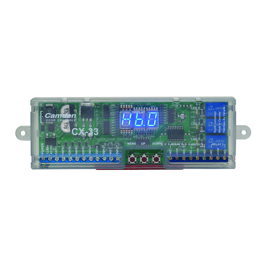
A total of 5 inputs (4 dry, and one wet or powered)
allow for more flexibility in wiring to different types of
activating devices.
The wet or powered input is
useful when connecting 3-terminal radio receivers, to
interfone panels, or for connecting to motors when
used as a Lock-out Relay.
The 3 buttons for mode selection, including separate
UP and DOWN buttons, offer fast and easy
programming. The large 3-segment display is the
easiest to view and understand in the industry.
A total of 3 heavy-duty 3 amp relays allow for varied
sequencing applications. For example, in restroom
use, the third relay is ideal for "Occupied" or "In Use"
signage. (Note: ouputs are dry, not powered.)
Section 2__________________
Installation
IMPORTANT: Do not apply power to the unit until
you have read the instructions fully and made the
required adjustments.
Mounting
The CX-33 should be mounted in a clean dry location
out of direct contact with the elements.
locations include inside a metal enclosure, operator
header, or above a false ceiling.
The Display & LED's are visible through the clear
plastic case, which also has cutouts for the
programming buttons and terminal strips. Once the
unit has been wired and adjusted, it may be tucked
up into the operator header or affixed using the
supplied Velcro or 2 sheet metal screws.
Wiring
Wiring of this unit is dependent on the mode desired,
however the following commonalities apply:
The unit will operate on 12 or 24 volts, AC or DC.
Connect to Terminals 1 & 2, which are non-polarity
sensitive.
NOTE:
regulated power supply when powering equipment in
certain modes such as the barrier-free washroom
application
maintained from a few minutes to many hours. We
offer a low-cost board-only regulated power supply -
CX-PS13, which will supply clean, filtered & regulated
12 or 24VDC power for the strike and CX-33.
General Programming Instructions
To enter the program mode, press the MENU button.
The current operating mode will display. Each time
you press the MENU button, the CX-33 will advance
& cycle through all 8 menu options. These are:
1. Mode (from 1 – 13)
2. Hold 1 = Relay 1 hold time
3. Delay 1 = Time from input ON until Relay 2
4. Hold 2 = Relay 2 hold time.
5. Delay 2 = Depends on mode
6. Hold 3 = Relay 3 hold time
7. Display Option = Sets display to be ON or
8. A = Delay on Activate. If other than zero is
Suitable
The UP and DOWN buttons will change the value of
each MENU item. (Holding down a button down will
increase the speed of scrolling).
If you do not touch any button for 10 seconds, the
CX-33 will return to Operating Mode. If you return to
Program Mode within 10 minutes, you can resume
where you left off. Otherwise the program will start
with the first menu item, which is Mode.
CX-33 Advanced Logic Relay
Installation Instructions
We highly recommend the use of a
where
the
strike
activates
OFF during Operating mode
selected, then the input must be held in for
the time period chosen before the CX-33 will
activate.
Firmware Ver. 2.5
power
may
be
Page 1 of 22
Advertisement

Related Manuals for CAMDEN CX-33


Summary of Contents for CAMDEN CX-33
- Page 1 8. A = Delay on Activate. If other than zero is selected, then the input must be held in for The CX-33 should be mounted in a clean dry location the time period chosen before the CX-33 will out of direct contact with the elements.
-
Page 2: Setup Instructions
(Mode 4) Proceed to section 3D on Page 3 input will have to be held for at least the time Apartment / Condo Applications indicated on the display before the CX-33 will (Mode 5) Proceed to section 3E on Page 3 activate. - Page 3 Timing adjustments may need to be made. The CX-33 is unique in the industry because it also provides the ability to add an adjustable “Walk-away” In addition, you can add a “Delay-on-activate” (or time. If the door input has been activated but the...
- Page 4 Push-to-Lock button (once door is in the closed indicated on the display before the CX-33 will position). The exterior wall switch is removed activate.
- Page 5 Operator (motor) to its control. If the motor is AC, then polarity is not an issue. The CX-33 The CX-33 also provides a relay dedicated for is triggered by the AC voltage going from high to low.
- Page 6 CX-33 Advanced Logic Relay Installation Instructions A unique feature of the CX-33 is the automatic reset Momentary switches connect to DRY 1 and/or WET feature. If a switch has been pressed, but the door terminals. Maintained devices connect to DRY 2 has not opened within 60 seconds (because it is input (optional).
-
Page 7: Technical Data
Camden Door Controls guarantees the CX-33 to be free from manufacturing defects for 3 years from date of sale. If during the first 3 years the CX-33 fails to perform correctly, it may be returned to our factory where it will be repaired or replaced (at our discretion) without charge. - Page 8 2" (51 mm) 7/8" (22 mm) Side View 5502 Timberlea Blvd Camden Door Controls Mississauga, Ontario L4W 2T7 SCALE: NONE DRAWN BY: DGW DATE: 08/13/13 REVISED: CX-33 Diagram A, Electrical and Mechanical End View CX-33 Electrical and DRAWING No: DRG-CX-33-A FILENAME: Mechanical.vsd...
- Page 9 5502 Timberlea Blvd Camden Door Controls Mississauga, Ontario L4W 2T7 Maintained SCALE: NONE DRAWN BY: DGW DATE: 07/05/13 REVISED: Signal on Input 3 holds (Mode 1) Basic Switching Network Wiring Diagram Output # 1 FIRE DRAWING No: DRG-CX-33-01 FILENAME: CX-33 Diagram 1.vsd...
- Page 10 5502 Timberlea Blvd Camden Door Controls N.C. Door 1 Mississauga, Ontario L4W 2T7 SCALE: NONE DRAWN BY: DGW DATE: 08/13/13 REVISED: Magnetic Contact (Mode 2) 2 Door Timed Airlock Wiring Diagram Switch N.C. Door 2 DRAWING No: DRG-CX-33-02 FILENAME: CX-33 Diagram 2.vsd...
- Page 11 5502 Timberlea Blvd Camden Door Controls N.C. Door 1 Mississauga, Ontario L4W 2T7 SCALE: NONE DRAWN BY: DGW DATE: 08/13/13 REVISED: Magnetic Contact (Mode 3) 2 Door Ratchet Airlock Wiring Diagram Switch N.C. Door 2 DRAWING No: DRG-CX-33-03 FILENAME: CX-33 Diagram 3.vsd...
- Page 12 Operator Operator 5502 Timberlea Blvd Camden Door Controls Mississauga, Ontario output L4W 2T7 ie - RF receiver SCALE: NONE DRAWN BY: DGW DATE: 07/05/13 REVISED: (optional) (Mode 4) Simple Bi-Directional Sequencer Wiring Diagram DRAWING No: DRG-CX-33-04a FILENAME: CX-33 Diagram 4a.vsd...
- Page 13 5502 Timberlea Blvd Camden Door Controls Mississauga, Ontario Optional L4W 2T7 Switches SCALE: NONE DRAWN BY: DGW DATE: 08/13/13 REVISED: Switch activates (Mode 4) 3 Relay Bi-directional Door Sequencer Wiring Diagram Relay 3 only DRAWING No: DRG-CX-33-04b FILENAME: CX-33 Diagram 4b.vsd...
- Page 14 5502 Timberlea Blvd Camden Door Controls Mississauga, Ontario L4W 2T7 Apartment Interphone SCALE: NONE DRAWN BY: DGW DATE: 07/05/13 REVISED: Panel (powered signal) (Mode 5) Apartment / Condo Application Wiring Diagram Unlocks door only DRAWING No: DRG-CX-33-05 FILENAME: CX-33 Diagram 5.vsd...
- Page 15 Camden Door Controls Sends a powered Mississauga, Ontario & maintained L4W 2T7 signal to keep door unlocked SCALE: NONE DRAWN BY: DGW DATE: 08/13/13 REVISED: for desired time. (Mode 6) Access Control Application Wiring Diagram DRAWING No: DRG-CX-33-06 FILENAME: CX-33 Diagram 6.vsd...
- Page 16 Camden Door Controls Mississauga, Ontario L4W 2T7 Inside Outside Inside Push to Lock Wall Switch Wall Switch SCALE: NONE DRAWN BY: DGW DATE: 02/08/09 REVISED: 08/27/12 Switch (Mode 7) Normally Unlocked Washroom Wiring Diagram DRAWING No: DRG-CX-33-07 FILENAME: CX-33 Diagram 7.vsd...
- Page 17 L4W 2T7 Inside Keypad, Key switch, Inside Push to Lock Prox Reader or similar Wall Switch SCALE: NONE DRAWN BY: DGW DATE: 02/08/09 REVISED: 08/27/12 Switch (Mode 8) Normally locked Washroom Wiring Diagram DRAWING No: DRG-CX-33-08 FILENAME: CX-33 Diagram 8.vsd...
- Page 18 5502 Timberlea Blvd Camden Door Controls Input #4 Mississauga, Ontario latches Relay 2. L4W 2T7 Second signal releases relay SCALE: NONE DRAWN BY: DGW DATE: 08/14/13 REVISED: (Mode 9) L.O.R plus Switching Network Wiring Diagram DRAWING No: DRG-CX-33-09 FILENAME: CX-33 Diagram 9.vsd...
- Page 19 LED 2 3. Sensor is only active after Switch is pressed, CX-33 and remains active until door closes. LED 3 4. The CX-33 also resets after 60 seconds if the Relay 1 Relay 2 Relay 3 door never opens. (safety feature) 5.
- Page 20 Mississauga, Ontario L4W 2T7 Fire Alarm Input. SCALE: NONE DRAWN BY: DGW DATE: 07/05/13 REVISED: N/O dry contact unlocks door (Mode 11) Deactivation Timer for Mag Lock Wiring Diagram and disables normal operation FIRE DRAWING No: DRG-CX-33-11 FILENAME: CX-33 Diagram 11.vsd...
- Page 21 Mississauga, Ontario L4W 2T7 Fire Alarm Input. SCALE: NONE DRAWN BY: DGW DATE: 07/05/13 REVISED: N/C dry contact unlocks door (Mode 12) Deactivation Timer for Mag Lock Wiring Diagram and disables normal operation FIRE DRAWING No: DRG-CX-33-12 FILENAME: CX-33 Diagram 12.vsd...
- Page 22 Door #1 Operator Push Switch 5502 Timberlea Blvd Camden Door Controls Activates Mississauga, Ontario Relays L4W 2T7 1 & 3 SCALE: NONE DRAWN BY: DGW DATE: 08/15/13 REVISED: (Mode 13) Special Sequencer Wiring Diagram DRAWING No: DRG-CX-33-13 FILENAME: CX-33 Diagram 13.vsd...
Need help?
Do you have a question about the CX-33 and is the answer not in the manual?
Questions and answers