
Subscribe to Our Youtube Channel
Related Manuals for auto maskin LT Series


Summary of Contents for auto maskin LT Series
- Page 1 Publication P/N 1500119 User Manual Marine Watch LT Series LT-ONE Alarm Panel LT-ACE Annunciator Panel...
-
Page 2: Table Of Contents
Table of contents 1 About this Manual 5.3.2 Assigning the Channel in a Template 1.1 Intended Audience 5.4 Login to the Panel 1.2 Responsibilities 5.4.1 Connection and Login 1.3 Revisions 5.5 Flexible I/O Configuration 2 Welcome to Marine Watch LT 5.6 Switch Channel Configuration 2.1 Introduction 5.6.1 Configure an Alarm Channel 18... -
Page 3: About This Manual
1.3 Revisions This User Manual is valid for the following firmware version of the Marine Watch LT Series, LT-ONE Alarm Panel and LT-ACE Annunciator Panel. Edition... -
Page 4: Welcome To Marine Watch Lt
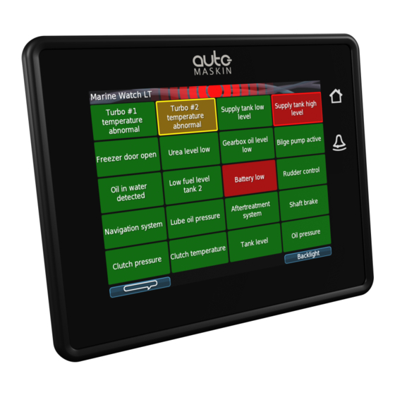
2 Marine Watch LT Series 2.1 Introduction The Marine Watch LT Series is a compact yet powerful alarm system. The front panel is a touch screen, and the main page typically displays a grid of maximum 20 rectangles. Each rectangle represents the status of an alarm (or warning) channel. -
Page 5: Web Server
2.3 Web Server The Marine Watch LT-ONE Alarm Panel configuration is performed with the built-in web server by logging in using the correct IP address. See the Configuration section for more information. Note! Configuration changes for the LT-ONE Alarm Panel automatically applies to all networked and connected LT-ACE Annunciator Panels. -
Page 6: Connector Pin-Reference
2.6 Connector Pin-reference Each of the four Deutsch™ DT-connectors has 12 pins and are referenced in the table below. Example: C1.11 = connector 1, pin 11 C2.7 2.6.1 LT-ONE Alarm Panel C2.8 Common Power Supply C2.9 C1.11 +12/24 VDC supply Magnetic Pickup C1.12 0 V supply... -
Page 7: Ace Annunciator Panel
C2.12 I/O #5 C1.4 Switch input #3 C3.1 I/O #6 / sensor power Common Alarm/Warning Relay C3.2 I/O #7 C2.1 C3.3 I/O #8 C2.2 Common C3.4 I/O #9 C2.3 C3.5 I/O #10 2.6.3 Crimp Tool C3.6 I/O #11 Use the correct crimp tool for the connector’s pin- and wire assembly. -
Page 8: Third-Party Communication Interface
2.7 Third-party Communication Interface Third-party panels can interface to the LT-ONE Alarm Panel using the built-in Modbus TCP interface on Ethernet. The I/O list and more information can be found here: https://goo.gl/MP7EQM Page 8 (24) -
Page 9: User Interface
3 User Interface 3.1 Header Information The header consists of the following information. ■ The Panel name Marine Watch LT. The name can be changed in the configuration. ■ A common warning/alarm banner. The entire centre of the header is flashing for new and unacknowledged events. -
Page 10: Buttons
3.2.1 Buttons There are two physical buttons on the Marine Watch LT panel. Operator Interface Toggle the view between Home Button Alarm Pages and the Menu. Silence buzzer and show the Alarm Button Alarm List. 3.2.2 Touch Screen The touch screen is divided into three large touch navigation areas as follows. If there is one page only, then pressing the Previous and Next page areas will have no effect. -
Page 11: Menu
3.3 Menu All operator settings, such as language selection, screen backlight, etc. is accomplished in the built-in menu structure of the Marine Watch LT. 3.4 Alarm List For the LT-ONE Alarm Panel, the Alarm List will show all alarms available. The LT-ACE Annunciator Panel will show a combined Alarm List for all connected LT-ONE Alarm Panels. -
Page 12: Alarm List Description
Alarm Panel source. In order to acknowledge an alarm, the alarm need to be selected by the operator and then acknowledged. 3.4.1 Alarm List Description The events are colored differently depending on the status as below. Alarm List 1: New active Alarm Bold text, red background 1: Acknowledged active Alarm Red background... -
Page 13: Alarm
3.5 Alarm Pages Depending on the configuration, the Marine Watch LT panel displays one or several (up to 9) pages. 3.5.1 The Alarm Grid Page Each rectangle represents the status of a binary/switch input channel, an analogue channel or a J1939 CAN bus signal. Each Alarm Grid page can display signal status for up to 20 channels. -
Page 14: Alarm Grid Description
Alarm Grid Description The rectangles in the Alarm Grid Page can take the following forms. Normal Active, Active, Inactive, unacknowledged acknowledged unacknowledged Flashing border Flashing border 4 Firmware Upgrade A firmware upgrade can be accomplished using a USB memory stick or using the built-in web server of the unit. -
Page 15: One Alarm Panel Configuration
5 LT-ONE Alarm Panel Configuration The configuration is solely required for the Marine Watch LT-ONE Alarm Panel. Configuration changes are automatically applied to all networked LT-ACE Annunciator Panels. 5.1 Introduction This section covers the basic configuration of the binary/switch and analogue I/O-channels of the Marine Watch LT-ONE Alarm Panel. -
Page 16: Login To The Panel
5.4 Login to the Panel Before any configuration can be done one must log in to the webserver of the panel. 5.4.1 Connection and Login Connect an Ethernet cable between a PC and the panel. In the URL-field of a web browser, type the IP-address of the panel. -
Page 17: Switch Channel Configuration
Note that the physical connector and pin reference (i.e. C1.4) for each I/O is given for each channel. Remember to press Submit to store the configuration. 5.6 Switch Channel Configuration Select the menu item home / lt-one / i/o configuration / switch The left margin lists 21 Switch Input channels. -
Page 18: Configure An Alarm Channel
5.6.1 Configure an Alarm Channel In this example, we are configuring Switch Channel #1 as an alarm channel. When the event trigger, it will indicate in red. In the Configure section from the above image, consider the following: ■ assign custom name: This is where the channel is given a descriptive text. ○... -
Page 19: Configure A Warning Channel
○ The Delay Before Event [sec] is the time delay after the switch changes state until the alarm activates. Typically a few seconds. ■ Finally, click the Submit button. The channel configuration is now stored in the panel. 5.6.2 Configure a Warning Channel In this example, we are configuring Switch Channel #2 as a warning channel. - Page 20 In this example, we are configuring the Voltage Sensor #10 as a warning channel with a high threshold limit of 50 %. When the event threshold is met, a yellow event will be raised. In the Configure section from the above image, consider the following: ■...
-
Page 21: Pages And Templates
○ The Event shall be Warning in this example. ○ Warning Threshold set to High and 50 %. ○ The Delay Before Event [sec] is the time delay after the switch changes state until the warning activates. Typically a few seconds. ■... -
Page 22: Assign Channels In The Template Page
5.8.2 Assign Channels in the Template Page In the template above there are 20 available slots. Each slot can be assigned a configured channel. From the drop-down list for each slot, choose the channel that shall be represented in that slot. -
Page 23: Ace Annunciator Panel Configuration
6 LT-ACE Annunciator Panel Configuration The Marine Watch LT-ACE Annunciator Panel can show alarms from one or two LT-ONE Alarm Panels. The Annunciator Panels are always in sync with the Alarm Panels. 6.1 Connect to LT-ONE Alarm Panel The LT-ACE Remote Panel must be configured to identify which LT-ONE Alarm Panel to connect to. -
Page 24: Web Interface
6.3 Web Interface Connect an Ethernet cable between a PC and the panel. In the URL-field of a web browser, type the IP-address of the panel. Type the username and password as follows ■ Username: lt ■ Default password: 1234 Page 24 (24)
Need help?
Do you have a question about the LT Series and is the answer not in the manual?
Questions and answers