
Related Manuals for Sel 421


Summary of Contents for Sel 421
- Page 1 SEL-421 Relay Protection and Automation System Instruction Manual User’s Guide 20090715 *PM421-01-NB* Courtesy of NationalSwitchgear.com...
- Page 2 © 2001–2009 by Schweitzer Engineering Laboratories, Inc. All rights reserved. All brand or product names appearing in this document are the trademark or registered trademark of their respective holders. No SEL trademarks may be used without written permission. SEL products appearing in this document may be covered by US and Foreign patents.
- Page 3 Preface ................................xxxi User’s Guide Section 1: Introduction and Specifications Features................................ U.1.2 Models and Options............................. U.1.5 SEL-421 Versions and Supported Features ....................U.1.7 Applications..............................U.1.8 Specifications ............................U.1.13 Section 2: Installation Shared Configuration Attributes........................U.2.1 Plug-In Boards............................U.2.12 Jumpers..............................U.2.18 Relay Placement ............................
- Page 4 230 kV Tapped Transmission Line Application Example................A.5.2 Section 6: SEL Communications Processor Applications SEL Communications Processors........................ A.6.1 SEL Communications Processor and Relay Architecture ................A.6.3 SEL Communications Processor Example....................A.6.5 Section 7: Direct Network Communication Direct Network Communication ......................... A.7.1 Serial Networking............................
- Page 5 Control Equation Programming ....................R.3.4 OGIC Control Equation Setting Structure ....................R.3.6 OGIC Multiple Setting Groups ..........................R.3.8 Control Equation Capacity ......................R.3.11 OGIC Control Equation Elements......................R.3.12 OGIC Control Equation Operators......................R.3.25 OGIC Effective Programming..........................R.3.35 SEL-311 and SEL-351 Series Users......................R.3.37 Date Code 20090715 SEL-421 Relay Courtesy of NationalSwitchgear.com...
- Page 6 Serial Communication ..........................R.4.2 Communications Card ..........................R.4.4 Section 5: SEL Communications Protocols Serial Port Hardware Protocol........................R.5.1 Software Protocol Selections........................R.5.2 Protocol Active When Setting PROTO := SEL ....................R.5.3 Virtual File Interface...........................R.5.11 SEL M Communications......................R.5.15 IRRORED SEL Distributed Port Switch Protocol (LMD) ...................R.5.21 SEL-2600A RTD Module Operation......................R.5.23...
- Page 7 Table of Contents Appendix A: Relay Word Bits Alphabetic..............................R.A.1 Row List ..............................R.A.22 Appendix B: Analog Quantities Quantities Listed Alphabetically .........................R.B.1 Quantities Listed by Function ........................R.B.8 Glossary Index SEL-421 Relay Command Summary Date Code 20090715 SEL-421 Relay Courtesy of NationalSwitchgear.com...
- Page 8 This page intentionally left blank Courtesy of NationalSwitchgear.com...
-
Page 9: Table Of Contents
Commissioning Testing...................... U.6.2 Table 6.3 Maintenance Testing ......................U.6.3 Table 6.4 UUT Database Entries for SEL-5401 Relay Test System Software—5 A Relay ....U.6.7 Table 6.5 UUT Database Entries for SEL-5401 Relay Test System Software—1 A Relay ....U.6.8 Table 6.6 Phase Instantaneous Overcurrent Pickup ................. - Page 10 Circuit Breaker Monitor Configuration................A.2.2 Table 2.2 Circuit Breaker Maintenance Information—Example ............A.2.4 Table 2.3 Contact Wear Monitor Settings—Circuit Breaker 1 ............A.2.5 Table 2.4 Circuit Breaker Monitor Initiate SEL Control Equations........... A.2.7 OGIC Table 2.5 Circuit Breaker Monitor Close SEL Control Equations..........A.2.9 OGIC Table 2.6...
- Page 11 SEL Communications Processors Port 1 Settings.............. A.6.5 Table 6.3 SEL Communications Processor Data Collection Automessages........A.6.6 Table 6.4 SEL Communications Processor Port 1 Automatic Messaging Settings ......A.6.6 Table 6.5 SEL Communications Processor Port 1 Region Map ............A.6.7 Table 6.6 SEL Communications Processor METER Region Map ............
- Page 12 Table 1.66 POTT Settings ........................R.1.94 Table 1.67 POTT Relay Word Bits .....................R.1.95 Table 1.68 DCUB Settings........................R.1.101 Table 1.69 DCUB Relay Word Bits ....................R.1.102 Table 1.70 Additional Settings for Single Pole Tripping (SPT) ............R.1.105 SEL-421 Relay Date Code 20090715 Courtesy of NationalSwitchgear.com...
- Page 13 Control Equation Programming Summary ..........R.3.2 OGIC Table 3.3 Definitions for Active Setting Group Indication Relay Word Bits SG1 Through SG6 ..R.3.9 Table 3.4 Definitions for Active Setting Group Switching SEL Control Equation OGIC Settings SS1 Through SS6 ....................R.3.9 Table 3.5 Summary of SEL Control Equation Elements ............R.3.12...
- Page 14 Table 4.17 TIME Command .......................R.4.18 Table 4.18 Communications Card Database Regions .................R.4.19 Table 4.19 SEL-421 Communications Card Database Structure—LOCAL Region ......R.4.19 Table 4.20 SEL-421 Communications Card Database Structure—METER Region ......R.4.20 Table 4.21 SEL-421 Communications Card Database Structure—DEMAND Region ......R.4.21 Table 4.22 SEL-421 Communications Card Database Structure—TARGET Region ......R.4.22...
- Page 15 Table 7.20 Fast Message Command Function Codes for Synchrophasor Fast Write ......R.7.31 Table 7.21 PMU Settings in the SEL-421 for SEL Fast Message Protocol, in Global Settings ..R.7.32 Table 7.22 SEL Fast Message Voltage and Current Selections Based on PHDATAV and PHDATAI ........................R.7.33...
- Page 16 List of Tables Table 8.1 IEC 61850 Document Set....................R.8.2 Table 8.2 Example IEC 61850 Descriptor Components ..............R.8.4 Table 8.3 SEL-421 Logical Devices ....................R.8.4 Table 8.4 Buffered Report Control Block Client Access ..............R.8.6 Table 8.5 Unbuffered Report Control Block Client Access..............R.8.7 Table 8.6 IEC 61850 Settings......................R.8.12...
- Page 17 Table 9.84 MET SYN Command......................R.9.33 Table 9.85 MET T Command ......................R.9.33 Table 9.86 OAC Command .........................R.9.34 Table 9.87 OPEN n Command......................R.9.34 Table 9.88 PAC Command ........................R.9.35 Table 9.89 PAS level new_password Command .................R.9.35 Date Code 20090715 SEL-421 Relay Courtesy of NationalSwitchgear.com...
- Page 18 TEST FM Command ......................R.9.54 Table 9.143 TEST FM DEM Command ....................R.9.55 Table 9.144 TEST FM OFF Command....................R.9.55 Table 9.145 TEST FM PEAK Command .....................R.9.56 Table 9.146 TIME Command .......................R.9.56 Table 9.147 TIME Q Command......................R.9.56 SEL-421 Relay Date Code 20090715 Courtesy of NationalSwitchgear.com...
- Page 19 Table 10.49 Negative-Sequence Instantaneous Overcurrent Pickup...........R.10.23 Table 10.50 Negative-Sequence Definite-Time Overcurrent Time Delay ..........R.10.24 Table 10.51 Negative-Sequence Instantaneous Definite-Time Overcurrent Torque Control....R.10.24 Table 10.52 Selectable Operating Quantity Inverse Time Overcurrent Element 1 ......R.10.24 Date Code 20090715 SEL-421 Relay Courtesy of NationalSwitchgear.com...
- Page 20 Table 10.92 Port Settings Categories ....................R.10.46 Table 10.93 Protocol Selection ......................R.10.46 Table 10.94 Communications Settings....................R.10.46 Table 10.95 SEL Protocol Settings .....................R.10.47 Table 10.96 DNP3 Serial Port Protocol Settings ................R.10.47 Table 10.97 Protocol Settings ..................R.10.48 IRRORED Table 10.98 RTD Protocol Settings.....................R.10.49 Table 10.99...
- Page 21 Relay Word Bits: Automation Latches................R.A.57 Table A.32 Relay Word Bits: Automation Sequencing Timers ............R.A.58 Table A.33 Relay Word Bits: Automation Counters................R.A.60 Table A.34 Relay Word Bits: SEL Control Equation Error and Status........R.A.62 OGIC Table A.35 Relay Word Bits: Relay Alarms ..................R.A.63 Table A.36 Relay Word Bits: Time Synchronization................R.A.63...
- Page 22 This page intentionally left blank Courtesy of NationalSwitchgear.com...
- Page 23 Major Component Locations on the SEL-421 Main Board A (or B)....... U.2.19 Figure 2.20 J18 Header—Password and Breaker Jumpers..............U.2.20 Figure 2.21 Major Component Locations on the SEL-421 INT1 (or INT2) I/O Board ...... U.2.23 Figure 2.22 Major Component Locations on the SEL-421 INT3 I/O Board........U.2.24 Figure 2.23 Major Component Locations on the SEL-421 INT4 I/O Board........
- Page 24 Typical External AC/DC Connections—Single Circuit Breaker ........U.2.51 Figure 2.47 Typical External AC/DC Connections—Dual Circuit Breaker........U.2.52 Figure 2.48 SEL-421 Example Wiring Diagram Using the Auxiliary {TRIP}/{CLOSE} Pushbuttons........................U.2.53 Figure 3.1 SEL Software License Agreement (Sample) ..............U.3.3 Figure 3.2 Windows Run Command Line to Load QuickSet........
- Page 25 Figure 4.61 Setting BK1TYP in QuickSet ..............U.4.70 ERATOR Figure 4.62 Uploading Global and Breaker Monitor Settings to the SEL-421 ........U.4.71 Figure 4.63 TIME BNC Connector, new hardware ................U.4.74 Figure 4.64 TIME BNC Connectors, old hardware................U.4.74 Figure 4.65 Retrofit Sticker .........................
- Page 26 QuickSet ......U.6.22 ERATOR Figure 6.14 Setting SER Points and Aliases: QuickSet ..........U.6.22 ERATOR Figure 6.15 Uploading Group 1 and Report Settings to SEL-421............U.6.23 Figure 6.16 HMI Tree View: QuickSet ..............U.6.24 ERATOR Figure 6.17 SER Report: QuickSet HMI..............U.6.24 ERATOR Figure 6.18...
- Page 27 Figure 6.25 Directional Settings: QuickSet..............U.6.32 ERATOR Figure 6.26 Uploading Group 1 and Breaker Monitor Settings to the SEL-421......... U.6.33 Figure 6.27 RELAY ELEMENTS LCD Screen Containing Elements F32Q and R32Q ....U.6.33 Figure 6.28 Finding Phase-to-Phase Test Quantities ................U.6.36 Figure 6.29...
- Page 28 SEL-421 Intelligent Circuit Breaker Monitor ..............A.2.2 Figure 2.2 Circuit Breaker Maintenance Curve (Manufacturer’s Data) ..........A.2.4 Figure 2.3 Circuit Breaker Contact Wear Curve With SEL-421 Settings ........... A.2.5 Figure 2.4 Trip Bus Sensing With Relay Input IN106 ................ A.2.8 Figure 2.5 Mechanical Operating Time for Circuit Breaker 1 A-Phase ..........
- Page 29 Figure 7.8 Example Telnet Session ....................A.7.12 Reference Manual Figure 1.1 Current and Voltage Source Connections for the SEL-421 Relay ........R.1.2 Figure 1.2 Main and Alternate Line Current Source Assignments ............R.1.3 Figure 1.3 Combined Currents for Line Current Source Assignment ..........R.1.3 Figure 1.4...
- Page 30 Figure 2.18 Voltage Check Element Logic...................R.2.46 Figure 2.19 Partial Breaker-and-a-Half or Partial Ring-Bus Breaker Arrangement......R.2.51 Figure 2.20 Voltage Angle Difference in a Paralleled System .............R.2.52 Figure 2.21 Synchronism-Check Voltages for Two Circuit Breakers...........R.2.52 SEL-421 Relay Date Code 20090715 Courtesy of NationalSwitchgear.com...
- Page 31 Figure 2.22 Synchronism-Check Settings ....................R.2.53 Figure 2.23 Synchronism-Check Relay Word Bits................R.2.54 Figure 2.24 Example Synchronism-Check Voltage Connections to the SEL-421 .......R.2.56 Figure 2.25 Synchronism-Check Voltage Reference................R.2.57 Figure 2.26 Normalized Synchronism-Check Voltage Sources VS1 and VS2........R.2.58 Figure 2.27 Healthy Voltage Window and Indication................R.2.59 Figure 2.28...
- Page 32 This page intentionally left blank Courtesy of NationalSwitchgear.com...
-
Page 33: User's Guide
Preface This manual provides information and instructions for installing and operating the SEL-421 Relay. The three volumes that comprise this manual are for use by power engineers and others experienced in protective relaying applications. Included are detailed technical descriptions of the relay and application examples. - Page 34 SEL control equations. Section 6: SEL Communications Processor Applications. Provides examples of how to use the SEL-421 with the SEL-2032, SEL-2030, and SEL-2020 Communications Processors for total substation automation solutions. SEL-421 Relay Date Code 20090715...
- Page 35 Contains a summary of Relay Word bits. Appendix B: Analog Quantities. Contains a summary of analog quantities. CD-ROM The CD-ROM contains the SEL-421 Relay Manual in an electronic form that you can search easily. Date Code 20090715 SEL-421 Relay Courtesy of NationalSwitchgear.com...
- Page 36 R stands for Reference Manual. control SEL trademarks and registered trademarks contain the appropri- OGIC equations ate symbol on first reference in a section. In the SEL-421 Instruc- tion Manual, certain SEL trademarks appear in small caps. These include SEL control equations, M communi-...
- Page 37 DANGER Indicates an imminently hazardous situation that, if not avoided, will result in death or serious injury. Date Code 20090715 SEL-421 Relay Courtesy of NationalSwitchgear.com...
- Page 38 Input S asserts output Q until input R asserts. SET RESET FLIP FLOP Output Q deasserts or resets when R asserts. FALLING EDGE B asserts at the falling edge of input A. SEL-421 Relay Date Code 20090715 Courtesy of NationalSwitchgear.com...
- Page 39 If your Raccordez-vous correctement à la terre, ainsi que la surface de travail facility is not equipped to work with these components, contact SEL et l’appareil avant d’en retirer un panneau. Si vous n’êtes pas équipés about returning this device and related SEL equipment for service.
- Page 40 Severe power and ground problems can occur on the communications Des problèmes graves d’alimentation et de terre peuvent survenir sur ports of this equipment as a result of using non-SEL cables. Never use les ports de communication de cet appareil si des câbles d’origine standard null-modem cables with this equipment.
- Page 41 WARNING Incorporated components, such as LEDs, transceivers, and laser Les composants internes tels que les leds (diodes emitters, are not user serviceable. Return units to SEL for repair or électroluminescentes), émetteurs-récepteurs ou émetteurs pour replacement. rayon laser ne peuvent pas être entretenus par l’usager. Retourner ces unités à...
- Page 42 This page intentionally left blank Courtesy of NationalSwitchgear.com...
- Page 43 QuickSet. ERATOR Synchrophasor measurements are available when a high-accuracy time source is connected to the relay. The SEL-421 supports the IEEE C37.118, Standard for Synchrophasors for Power Systems. A simple and robust hardware design features efficient digital signal processing. Combined with extensive self-testing, these features provide relay reliability and enhance relay availability.
-
Page 44: Figure 1.1 Sel-421 Functional Overview
Breaker Failure. The SEL-421 incorporates CT subsidence detection to produce element dropout in 5/8 cycle. Apply the SEL-421 to supply three-pole breaker failure for one or two breakers. Included is the necessary logic for single-pole and three-pole breaker failure retrip and initiation of transfer tripping. - Page 45 Introduction and Specifications U.1.3 Features Out-of-Step Blocking and Tripping. Select out-of-step blocking of distance elements or out-of-step tripping during power swings. The SEL-421 includes multizone elements and logic for detection of an out-of-step condition. Switch-Onto-Fault. Relay switch-onto-fault (SOTF) logic permits specific protection elements to quickly trip after the circuit breaker closes, protecting maintenance personnel and substation equipment.
- Page 46 The lowercase xs in the above part numbers represent fields that contain other values that are not important in determining the operator controls of the relay. Refer to the SEL-421 Model Option Table for complete part number details. These tables are available on the SEL website or from the factory.
- Page 47 Introduction and Specifications U.1.5 Models and Options Models and Options Consider the following options when ordering and configuring the SEL-421. ➤ Chassis size ➢ 3U, 4U, and 5U (U is one rack unit—1.75 inches or 44.45 mm) ➤ Main board I/O...
- Page 48 Communications protocols ➢ Complete group of SEL protocols (SEL ASCII, SEL Compressed ASCII, SEL Settings File Transfer, SEL Fast Meter, SEL Fast Operate, SEL Fast SER, RTDs, Enhanced M IRRORED Communications), and Synchrophasors (SEL Fast Message and IEEE C37.118 format).
- Page 49 ➢ ® Plug-in/plug-out PT and shorting CT Connectorized versions Contact the SEL factory or your local Technical Service Center for particular part number and ordering information (see Factory Assistance on page U.6.45). You can also view the latest part number and ordering information on the SEL website at www.selinc.com.
- Page 50 Firmware versions R102–R112 provide synchrophasors using the SEL Fast Message protocol in the SEL-421-0. Firmware versions R123 and older do not provide this feature. Firmware versions R115 and older do not provide support for Main Board B, INT2, INT7, and INT8 interface boards.
-
Page 51: Figure 1.3 Single Circuit Breaker Configuration (Ess := 1)
Introduction and Specifications U.1.9 Applications SEL-421 Relay Analog Input Function CB1 protection, line protection Line protection Synchronism check Figure 1.3 Single Circuit Breaker Configuration (ESS := 1) SEL-421 Relay Analog Input Function CB1 protection, line protection CB1 breaker failure Line protection Synchronism check Figure 1.4 Single Circuit Breaker Configuration With Line Breaker CTs... -
Page 52: Figure 1.6 Double Circuit Breaker Configuration With Bus Protection (Ess := 4)
U.1.10 Introduction and Specifications Applications BUS 1 BUS 2 SEL-421 Relay Analog Input Function IW+IX CB2 protection Line protection CB1 protection Line protection Synchronism check Circuit Breaker 1 Synchronism check Circuit Breaker 2 Figure 1.6 Double Circuit Breaker Configuration With Bus Protection... -
Page 53: Table 1.1 Application Highlights
Introduction and Specifications U.1.11 Applications Application Apply the SEL-421 in power system protection and control situations. Table 1.1 lists applications and key features of the relay. Highlights Table 1.1 Application Highlights (Sheet 1 of 2) Application Key Features Single-pole and... - Page 54 OGIC equations for complete flexibility Synchrophasors The SEL-421 can function as a phasor measurement unit (PMU) at the same time as it provides best-in-class protective relay functions. C37.118 message format allows up to eight current and four voltage synchronized measurements, up to 60 messages per second (on a 60 Hz nominal power system).
- Page 55 0.30 A L/R = 40 ms Carry: 6 A continuous carry 250 Vdc 0.20 A L/R = 40 ms 1 s Rating: 50 A MOV Protection: 250 Vac/330 Vdc/130 J Date Code 20090715 User’s Guide SEL-421 Relay Courtesy of NationalSwitchgear.com...
- Page 56 Dropout <75 Vdc Nominal Voltage: 5 Vdc +10% 220 Vdc: Pickup 176–264 Vdc; Maximum Voltage: 8 Vdc Dropout <132 Vdc Input Impedance: 2500 ohms 250 Vdc: Pickup 200–300 Vdc; Dropout <150 Vdc SEL-421 Relay User’s Guide Date Code 20090715 Courtesy of NationalSwitchgear.com...
- Page 57 IEC 60255-22-2:1996, Levels 1, 2, 3, 4 –40° to +85°C (–40° to +185°F) IEC 61000-4-2:1995, Levels 1, 2, 3, 4 IEEE C37.90.3-2001, SEL-421 with Ethernet card: Levels 2, 4, and 8 kV contact; –40° to +75°C (–40° to +167°F) Levels 4, 8, and 15 kV air Note: LCD contrast impaired for temperatures below –20°...
- Page 58 Zone 1 Transient <5% of setting plus steady-state Overreach: accuracy Storage: 35 quarter-second events or SEL-421-0 and 24 half-second events SEL-421-3 Maximum Maximum Duration: Record events as long as 5 seconds Operating Time: 0.8 cycle at 70% of reach and SIR = 1...
- Page 59 PT 100, NI 100, NI 120, and CU 10 RTD-Types Supported, Field 0.01 A steps Selectable Accuracy (Steady State) Up to 500 m Fiber-Optic Cable to SEL-2600 RTD Module 5 A Model: ±0.05 A plus ±3% of setting Breaker Failure Instantaneous Overcurrent 1 A Model: ±0.01 A plus ±3% of setting...
- Page 60 At 1.0 • I TCLSBK1, TCLSBK2: 1.00–30.00 cycles, 0.25 cycle steps Power factor unity: ±0.4% Zone Time Delay: 0.000–16000 cycles, 0.125 cycle steps Power factor 0.5 lag, 0.5 lead: ±0.4% SEL-421 Relay User’s Guide Date Code 20090715 Courtesy of NationalSwitchgear.com...
- Page 61 ±5 Hz of nominal (50 or 60 Hz) Voltage Range: 30 V–150 V Current Range: (0.1–2) • I = 1 A or 5 A) Phase Angle Range: –179.99° to 180° Date Code 20090715 User’s Guide SEL-421 Relay Courtesy of NationalSwitchgear.com...
- Page 62 This page intentionally left blank Courtesy of NationalSwitchgear.com...
- Page 63 Connection on page U.2.31 ➤ AC/DC Connection Diagrams on page U.2.50 It is also very important to limit access to the SEL-421 settings and control functions by using passwords. For information on relay access levels and passwords, see Changing the Default Passwords: Terminal on page U.4.9.
- Page 64 PT and CT secondaries. Connectorized The Connectorized SEL-421 features receptacles that accept plug-in/plug-out connectors for terminating PT and CT inputs; this requires ordering a wiring harness (SEL-WA0421) with mating plugs and wire leads.
-
Page 65: Figure 2.1 Horizontal Front-Panel Template (A); Vertical Front-Panel Template (B)
Installation U.2.3 Shared Configuration Attributes Operator Control Labels Target Opening Label Opening Target Label Operator Control Labels Opening Figure 2.1 Horizontal Front-Panel Template (a); Vertical Front-Panel Template (b) Date Code 20090715 User’s Guide SEL-421 Relay Courtesy of NationalSwitchgear.com... -
Page 66: Figure 2.2 Rear 3U Template, Fixed Terminal Block Analog Inputs
(In a vertical-mount relay, the right rear side is at the top.) Secondary Circuits The SEL-421 is a very low burden load on the CT secondaries and PT secondaries. For both the CT and PT inputs, the frequency range is 40–65 Hz. -
Page 67: Table 2.1 Recommended Control Input Pickup Settings
Control Inputs Direct Coupled The SEL-421 Main Board A inputs, and the inputs on the optional I/O interface boards (INT1, INT5, or INT6 I /O boards—see Models and Options on page U.1.5), are direct-coupled, high-impedance control inputs. - Page 68 16 times per cycle. See Raw and Filtered Data on page A.3.2. Optoisolated The SEL-421 Main Board B inputs, and the inputs on the optional I/O interface boards (INT2, INT3, INT4, INT7, or INT8 I/O boards—see Models and Options on page U.1.5), are fixed pickup threshold, optoisolated, control...
-
Page 69: Table 2.2 Required Settings For Use With Ac Control Signals
First set Global setting EICIS := Y to gain access to the individual input pickup and dropout timer settings. These are the only setting values that SEL recommends for detecting ac control signals. Other values may result in inconsistent operation. -
Page 70: Figure 2.4 Standard Control Output Connection
Form A Hybrid control output on the main board I/O terminals. OUT01 Figure 2.5 Hybrid Control Output Connection Section 1: Introduction and Specifications, for complete Hybrid control output specifications. SEL-421 Relay User’s Guide Date Code 20090715 Courtesy of NationalSwitchgear.com... -
Page 71: Figure 2.6 Fast Hybrid Control Output Connection, Int5 (Int8)
A third terminal (03 in Figure 2.8) provides an internal path for precharging the Fast Hybrid output circuit capacitance when the circuit is open. Date Code 20090715 User’s Guide SEL-421 Relay Courtesy of NationalSwitchgear.com... -
Page 72: Figure 2.8 Fast Hybrid Control Output Typical Terminals, Int5 (Int8)
Fast Hybrid control output has only two terminal connections. Main Board I/O The SEL-421 base model is a 3U chassis with I/O interface on the main board (the top board). See Figure 2.27 Figure 2.28 for representative rear-panel views of the 3U chassis rear panel. - Page 73 IRIG time mode. There are two IRIG-B inputs on the SEL-421 rear panel, but only one is capable of supporting the HIRIG mode. For input specifications, see...
-
Page 74: Figure 2.10 Int1 I/O Interface Board
WAN, and IEC 61850 applications on an Ethernet network. This card is only available at the time of purchase of a new SEL-421 as a factory-installed option or as a factory-installed conversion to an existing relay. -
Page 75: Figure 2.11 Int2 I/O Interface Board
Figure 2.15 INT6 I/O Interface Board Figure 2.16 INT7 I/O Interface Board Figure 2.17 INT8 I/O Interface Board The I/O interface boards carry jumpers that identify the board location (see Jumpers on page U.2.18). Date Code 20090715 User’s Guide SEL-421 Relay Courtesy of NationalSwitchgear.com... -
Page 76: Table 2.3 I/O Interface Boards Control Inputs
Common Contacts INT1 INT2 INT3 Two sets of 9 NOTE: The SEL-421-0 and the SEL-421-1 do not support Main Board B INT4 Two sets of 9 I/O and INT2, INT3, INT7, and INT8 I/O interface boards. See SEL-421 INT5 Versions and Supported Features on page U.1.7... -
Page 77: Table 2.4 I/O Interface Boards Control Outputs
Main Board B High-Speed/High-Current Interrupting. High-Current Interrupting. Installing Optional I/O Interface Boards Perform the following steps to expand the capability of the SEL-421 with additional I/O interface boards: Step 1. Follow your company standard to remove the relay from service. -
Page 78: Figure 2.18 Chassis Key Positions For I/O Interface Boards
Version Number on page U.6.39. If the firmware version is R111 or lower, you b. Slide the I/O interface board into the SEL-421 by must first upgrade the relay firmware to the newest version and verify that pushing the front edge of the board drawout tray. - Page 79 Tighten the screw terminal connector mounting screws to between 7 in-lb. and 12 in-lb. (0.8 Nm to 1.4 Nm). Step 15. Reinstall the SEL-421 main board, and reconnect the power, the interface board, and the analog input board cables.
-
Page 80: Table 2.5
The jumpers are located on the main board (the top board) and the I/O interface boards (one or two boards located immediately below the main board). Main Board Jumpers The jumpers on the main board of the SEL-421 perform these functions: ➤ Temporary/emergency password disable ➤... -
Page 81: Figure 2.19 Major Component Locations On The Sel-421 Main Board A (Or B)
Installation U.2.19 Jumpers Figure 2.19 Major Component Locations on the SEL-421 Main Board A (or B) Date Code 20090715 User’s Guide SEL-421 Relay Courtesy of NationalSwitchgear.com... - Page 82 The SEL-421 ships with circuit breaker jumper J18C OFF. For commissioning and testing of the SEL-421 contact outputs, it may be convenient to set J18C ON, so that the PULSE OUTnnn commands can be used to check output wiring.
-
Page 83: Table 2.6 Main Board Jumpers-Jmp1, Jmp2, And Jmp3
JMP1, JMP2, and JMP3 positions. Refer to Figure 2.19 for the locations of these jumpers. The SEL-421 ships with JMP1, JMP2, and JMP3 OFF (no +5 Vdc on Pin 1). Table 2.6 Main Board Jumpers—JMP1, JMP2, and JMP3... - Page 84 Step 12. Install or remove the jumper as needed (see Table 2.6 jumper position descriptions). Step 13. Reinstall the SEL-421 main board, and reconnect the power, the interface board, and the analog input board cables. Step 14. Reconnect the cable removed in...
-
Page 85: Figure 2.21 Major Component Locations On The Sel-421 Int1 (Or Int2) I/O Board
Installation U.2.23 Jumpers JMP1B JMP1A JMP2B JMP2A Figure 2.21 Major Component Locations on the SEL-421 INT1 (or INT2) I/O Board Date Code 20090715 User’s Guide SEL-421 Relay Courtesy of NationalSwitchgear.com... -
Page 86: Figure 2.22 Major Component Locations On The Sel-421 Int3 I/O Board
U.2.24 Installation Jumpers JMP6 JMP3 JMP8 JMP4 JMP5 JMP7 Figure 2.22 Major Component Locations on the SEL-421 INT3 I/O Board SEL-421 Relay User’s Guide Date Code 20090715 Courtesy of NationalSwitchgear.com... -
Page 87: Figure 2.23 Major Component Locations On The Sel-421 Int4 I/O Board
Installation U.2.25 Jumpers Figure 2.23 Major Component Locations on the SEL-421 INT4 I/O Board Date Code 20090715 User’s Guide SEL-421 Relay Courtesy of NationalSwitchgear.com... -
Page 88: Figure 2.24 Major Component Locations On The Sel-421 Int5 (Or Int8) I/O Board
U.2.26 Installation Jumpers JMP1B JMP1A JMP2B JMP2A Figure 2.24 Major Component Locations on the SEL-421 INT5 (or INT8) I/O Board SEL-421 Relay User’s Guide Date Code 20090715 Courtesy of NationalSwitchgear.com... -
Page 89: Figure 2.25 Major Component Locations On The Sel-421 Int6 (Or Int7) I/O Board
Jumpers JMP1B JMP1A JMP2B JMP2A Figure 2.25 Major Component Locations on the SEL-421 INT6 (or INT7) I/O Board To confirm the positions of your I/O board jumpers, remove the front panel and visually inspect the jumper placements. Table 2.7 lists the four jumper positions for I/O interface boards. -
Page 90: Table 2.7 I/O Board Jumpers
Change the I/O interface board jumpers only when you move the slot position of an I/O board. You must remove the I/O interface boards to access the jumpers. Perform the following steps to change jumpers on an SEL-421 I/O interface board: Step 1. -
Page 91: Table 2.8 Jumper Positions For Breaker Open/Close Indication
Table 2.10 Front-Panel LED Option JMP11, JMP12 LED Color BRIDGE Pins 1 and 3 Pins 2 and 4 BRIDGE Green Pins 3 and 5 Pins 4 and 6 JMP11 Open; JMP12 Closed. Date Code 20090715 User’s Guide SEL-421 Relay Courtesy of NationalSwitchgear.com... - Page 92 U.2.30 Installation Relay Placement Relay Placement Proper placement of the SEL-421 helps make certain that you receive years of trouble-free power system protection. Use the following guidelines for proper physical installation of the SEL-421. Physical Location You can mount the SEL-421 in a sheltered indoor environment (a building or an enclosed cabinet) that does not exceed the temperature and humidity ratings for the relay.
-
Page 93: Figure 2.26 Sel-421 Chassis Dimensions
U.2.31 Connection Figure 2.26 SEL-421 Chassis Dimensions Panel Mounting Place the panel-mount versions of the SEL-421 in a switchboard panel. See the drawings in Figure 2.26 for panel cut and drill dimensions (these dimensions apply to both the horizontal and vertical panel-mount relay versions). -
Page 94: Figure 2.27 3U Rear Panel, Main Board A
Figure 2.28 shows the Connectorized 3U horizontal interface boards. See SEL-421 configuration of the SEL-421. For clarity, the figures do not show a Versions and Supported Features on communications card installed in PORT 5. page U.1.7 for details. -
Page 95: Figure 2.29 4U Rear Panel, Main Board A, Without Optional I/O
Figure 2.29 4U Rear Panel, Main Board A, Without Optional I/O i3362d Figure 2.30 4U Rear Panel, Main Board A, INT5 I/O Interface Board i3928a Figure 2.31 4U Rear Panel, Main Board B, INT8 I/O Interface Board Date Code 20090715 User’s Guide SEL-421 Relay Courtesy of NationalSwitchgear.com... -
Page 96: Figure 2.32 5U Rear Panel, Main Board B, Int3 And Int1 I/O Interface Board
(The INT3 board is the 200-addresses slot; the INT1 board is the 300-addresses slot.) i3812b Figure 2.33 5U Rear Panel, Main Board A, INT4 and INT1 I/O Interface Board (The INT4 board is the 200-addresses slot; the INT1 board is the 300-addresses slot.) SEL-421 Relay User’s Guide Date Code 20090715 Courtesy of NationalSwitchgear.com... -
Page 97: Figure 2.34 5U Rear Panel, Main Board A, Int6 And Int4 I/O Interface Board
Figure 2.35 5U Rear Panel, Main Board B, INT2 and INT7 I/O Interface Board Rear-Panel Symbols There are important safety symbols on the rear of the SEL-421 (see Figure 2.36). Observe proper safety precautions when you connect the relay at terminals marked by these symbols. -
Page 98: Figure 2.36 Rear-Panel Symbols
9 in-lb. to 18 in-lb. (1.0 Nm to 2.0 Nm). You can remove the screw terminal connectors from the rear of the SEL-421 by unscrewing the screws at each end of the connector block. Perform the following steps to remove a screw terminal connector: Step 1. -
Page 99: Figure 2.37 Screw Terminal Connector Keying
Use 12–10 AWG (4 mm –6 mm ) wire less than 6.6 feet (2 m) in length for this connection. This terminal connects directly to the internal chassis ground of the SEL-421. Date Code 20090715 User’s Guide SEL-421 Relay Courtesy of NationalSwitchgear.com... -
Page 100: Figure 2.38 Rear-Panel Receptacle Keying, Sel-421
Power Connections The terminals labeled POWER on the rear panel (#Z29 and #Z30) must connect to a power source that matches the power supply characteristics that your SEL-421 specifies on the rear-panel serial number label. (See Power Supply SEL-421 Relay User’s Guide... -
Page 101: Table 2.11 Fuse Requirements For The Sel-421 Power Supply
Place an external disconnect device, switch/fuse combination, or circuit breaker in the POWER leads for the SEL-421; this device must interrupt both the hot (H/+) and neutral (N/–) power leads. The current rating for the power disconnect circuit breaker or fuse must be 20 A maximum. - Page 102 Connection Power Supply Fuse Replacement You can replace a bad fuse in an SEL-421 power supply, or you can return the SEL-421 to SEL for fuse replacement. If you decide to replace the fuse, perform the following steps to replace the power supply fuse: Step 1.
-
Page 103: Figure 2.39 Ps30 Power Supply Fuse Location
600 V lead to Terminal #Z28. (rms or dc). Secondary Circuit The SEL-421 has two sets of three-phase current inputs and two sets of three- phase voltage inputs. Shared Configuration Attributes on page U.2.1 describes Connections these inputs in detail. - Page 104 Odd numbered terminals are the polarity terminals. You can install these connectors in only one orientation. Control Circuit You can configure the SEL-421 with many combinations of control inputs and control outputs. See Main Board I/O on page U.2.10 I/O Interface Boards Connections on page U.2.12...
- Page 105 Alarm Output The SEL-421 monitors internal processes and hardware in continual self-tests. If the relay senses an out-of-tolerance condition, the relay declares a Status Warning or a Status Failure. The relay signals a Status Warning by pulsing the HALARM Relay Word bit (hardware alarm) to a logical 1 for five seconds.
-
Page 106: Figure 2.40 Control Output Out108
The SEL-421 also pulses the BADPASS Relay Word bit after three unsuccessful password entry attempts. You can add the software alarm SALARM to the alarm output by entering the... - Page 107 Conventional fiber-optic and telephone modems do not support IRIG-B signal transmission. Use the SEL-2810 transceiver to provide long distance delivery of the IRIG-B signal to the SEL-421. The SEL-2810 includes a channel for the IRIG-B time code. These transceivers enable you to synchronize time precisely from IRIG-B time code generators (such as the SEL-2032 Communications Processor) over a fiber-optic communications link.
- Page 108 Connection Obsolete TIME Input Connection Previous SEL-421 relays had a TIME 1k PPS input BNC connector. When relay firmware version R112 was released, the rear-panel TIME inputs were reconfigured. If you have upgraded the firmware in a previous SEL-421, see Using New SEL-421 Firmware in an Existing Relay on page U.4.73...
-
Page 109: Figure 2.41 Sel-421 To Computer-D-Subminiature 9-Pin Connector
Making an EIA-232 Serial Port Connection on page U.4.5). Figure 2.41 shows the configuration of SEL Cable C234A that you can use for basic ASCII and binary communication with the relay. A properly configured ASCII terminal, terminal emulation program, or QuickSet... -
Page 110: Figure 2.42 Example Ethernet Panel With Fiber-Optic Ports
Network Connections The optional Ethernet card for the SEL-421 can use either the connection on Port A or Port B to operate on a network. These ports work together to provide a primary and backup interface, as described in... -
Page 111: Figure 2.43 Two 10/100Base-T Port Configuration
Shielded Twisted Pair (STP) cables are often used in industrial adequate immunity to interference in applications. The SEL-421 Ethernet card is compatible with standard UTP electrically noisy environments unless additional shielding measures are cables for Ethernet networks as well as STP cables for Ethernet networks. - Page 112 Ethernet card. AC/DC Connection Diagrams You can apply the SEL-421 in many power system protection schemes. Figure 2.46 shows one particular application scheme with connections that represent typical interfaces to the relay for a single circuit breaker connection.
-
Page 113: Figure 2.46 Typical External Ac/Dc Connections-Single Circuit Breaker
Lock Out Breaker (—) Failure OUT103 86B1 Trip Circuit Alarm to OUT108 Annunciator, RTU, Circuit or SEL-2020/2030 Breaker SEL-421 Relay Synch Check (—) IN101 Breaker Status 1 52A1 (—) Breaker IN102 Failure Lock Out BF LO I POL (—) Power Power (—) -
Page 114: Figure 2.47 Typical External Ac/Dc Connections-Dual Circuit Breaker
(—) Breaker 2 Trip Coil 52A2 Trip Circuit OUT201 (—) Breaker 2 Close Coil 52B2 Close Circuit OUT202 Forward Direction LINE SEL-421 Relay (—) Bus2 Breaker Failure Lock Out 86B2 OUT203 Trip Circuit LINE PTs (—) IN101 Breaker Status 1... -
Page 115: Figure 2.48 Sel-421 Example Wiring Diagram Using The Auxiliary {Trip}/{Close} Pushbuttons
Manual Close Pushbutton Open Closed Pushbutton Local Remote Close/ Auto-Reclose Remote Trips/ Protection Trips To Close Circuit — — Figure 2.48 SEL-421 Example Wiring Diagram Using the Auxiliary {TRIP}/{CLOSE} Pushbuttons Date Code 20090715 User’s Guide SEL-421 Relay Courtesy of NationalSwitchgear.com... - Page 116 This page intentionally left blank Courtesy of NationalSwitchgear.com...
- Page 117 QuickSet for easier, more efficient ERATOR configuration of relay settings, metering, and control. ERATOR OGIC ® QuickSet gives you the advantages of rules-based settings checks, SEL control equation Expression Builder, operator control and metering HMI, and event analysis. Date Code 20090715 User’s Guide SEL-421 Relay Courtesy of NationalSwitchgear.com...
- Page 118 However, you do not have to use QuickSet to configure the ERATOR SEL-421; you can continue to use an ASCII terminal or a computer running terminal emulation software to access all relay settings and metering. Installing the Computer Software Load QuickSet on an IBM-compatible PC.
-
Page 119: Figure 3.1 Sel Software License Agreement (Sample)
CD-ROM drive in your PC (the CD-ROM drive in the Figure 3.2 example is drive D:\). Step 3. The SEL Software License Agreement appears (Figure 3.1). Figure 3.2 Windows Run Command Line to Load... - Page 120 PC Software Communications Setup Communications Setup QuickSet uses the relay communications ports to ERATOR communicate with the SEL-421. Configure the QuickSet ERATOR Communication Parameters menu settings to communicate effectively with the relay. You can also use a basic terminal emulation window any time you run QuickSet.
-
Page 121: Figure 3.4 Ac Sel Erator Quickset Network Parameters Dialog Box: Ftp
Many third-party terminal emulation programs are available with file transfer encoding schemes. Click Communication > Terminal to start the terminal emulation window. Another convenient method to start the terminal is to type <Ctrl+T>. Date Code 20090715 User’s Guide SEL-421 Relay Courtesy of NationalSwitchgear.com... - Page 122 Relay Database The default relay database file already configured in QuickSet ERATOR is Relay.rdb. This database may contain example settings files for the SEL products with which you can use QuickSet. ERATOR Perform the following steps to access and/or modify the database: Step 1.
-
Page 123: Figure 3.7 Database Manager Copy/Move In Ac Sel Erator Quickset
Move removes the relay from one database and places the relay in another database. Step 5. Reverse this process to copy or move relays from Database B to Database A. Figure 3.7 Database Manager Copy/Move in QuickSet ERATOR Date Code 20090715 User’s Guide SEL-421 Relay Courtesy of NationalSwitchgear.com... - Page 124 The first portion of the Z-number is the ERATOR QuickSet settings driver version number (see Figure 3.8). Relay Settings Version Number FID = SEL-421-R101-V0-Z001001-D20020104 HMI Version Number Figure 3.8 QuickSet Driver Information in the FID String ERATOR SEL-421 Relay User’s Guide Date Code 20090715 Courtesy of NationalSwitchgear.com...
-
Page 125: Figure 3.9 Hmi Driver Version Number In The Hmi Window
Figure 3.9 HMI Driver Version Number in the HMI Window As SEL develops new drivers, you can update your existing ERATOR QuickSet software with specific relay drivers for each SEL product that uses QuickSet. Contact your local Technical Service Center or the ERATOR SEL factory for the latest QuickSet drivers. - Page 126 Settings Editor Selection dialog box (see Figure 3.11). QuickSet uses the Z-number in the relay FID string to create a ERATOR particular version of relay settings (see Drivers on page U.3.8). SEL-421 Relay User’s Guide Date Code 20090715 Courtesy of NationalSwitchgear.com...
- Page 127 Figure 3.13 appears. QuickSet uses serial protocols at a serial port or FTP from an ERATOR Ethernet port to read settings from SEL devices. Figure 3.13 Reading Relay Settings in QuickSet ERATOR Relay Editor Use the Relay Editor to enter relay settings.
- Page 128 QuickSet to control a particular relay, you should confirm that ERATOR QuickSet part number matches the relay part number so ERATOR that you can access all of the settings you need for your relay. SEL-421 Relay User’s Guide Date Code 20090715 Courtesy of NationalSwitchgear.com...
-
Page 129: Figure 3.15 Retrieving The Relay Part Number
The Relay Part Number dialog box appears, as shown in Figure 3.16. Step 4. Use the arrows inside the text boxes to match corresponding portions of the Relay Part Number dialog box to your relay. Date Code 20090715 User’s Guide SEL-421 Relay Courtesy of NationalSwitchgear.com... - Page 130 (Relay Word bits) and analog quantities in the relay. QuickSet simplifies this process with the Expression Builder, ERATOR a rules-based editor for programming SEL control equations. The OGIC Expression Builder organizes relay elements, analog quantities, and...
-
Page 131: Figure 3.17 Location Of The Expression Builder Option Buttons
QuickSet Expression Builder ERATOR Using the Expression For Protection Free-Form SEL and Automation Free Form SEL OGIC OGIC select the type of result (LVALUE) for the SEL control equation to use OGIC Builder the Expression Builder. QuickSet shows these possibilities in ERATOR the file box directly underneath the left side of the equation. -
Page 132: Figure 3.19 Retrieving Relay Event History
SEL-421 stores to evaluate the performance of a protection system. Event Waveforms The SEL-421 records power system events for all trip situations and for other operating conditions that you program with SEL control equations (see... - Page 133 (see Figure 3.20 NOTE: If your PC is loaded with Figure 3.21). SEL-5601 Analytic Assistant software (purchased separately), ERATOR QuickSet ® SEL-5030 Software You can see high-accuracy time-stamp information on the event automatically uses SEL-5601 to oscillogram.
-
Page 134: Figure 3.21 Sample Event Oscillogram
A phasor display similar to Figure 3.23 appears. Figure 3.22 Retrieving Event Report Waveforms Figure 3.23 Sample Phasors Event Waveform Screen SEL-421 Relay User’s Guide Date Code 20090715 Courtesy of NationalSwitchgear.com... -
Page 135: Figure 3.24 Sample Harmonic Analysis Event Waveform Screen
Step 4. Click Summary Data on the Event Waveform View menu to see event summary information and to confirm that you are viewing the correct event. Figure 3.25 shows a sample QuickSet Event ERATOR Report Summary screen. Date Code 20090715 User’s Guide SEL-421 Relay Courtesy of NationalSwitchgear.com... -
Page 136: Figure 3.25 Sample Event Report Summary Screen
Step 2. At the Event Waveform dialog box, you can select the Phasors display, the Harmonic Analysis display, the Summary Data display, and the Settings display from the Event Waveform window (see Read History on page U.3.16). SEL-421 Relay User’s Guide Date Code 20090715 Courtesy of NationalSwitchgear.com... - Page 137 Step 2. Click the button marked Disable Update to suspend HMI use of the communications channel. Figure 3.27 QuickSet HMI Features ERATOR Date Code 20090715 User’s Guide SEL-421 Relay Courtesy of NationalSwitchgear.com...
- Page 138 A table showing the latest circuit breaker monitor data. Control Window Metering and records reset buttons, trip and close control, out- put pulsing, target reset, time and date set, group switch, and remote bit control. SEL-421 Relay User’s Guide Date Code 20090715 Courtesy of NationalSwitchgear.com...
- Page 139 Understanding basic relay operation principles and methods will help you use the relay effectively. This section presents the fundamental knowledge you need to operate the SEL-421, organized by task. These tasks help you become familiar with the relay and include the following: ➤...
-
Page 140: Figure 4.1 Sel-421 Serial Number Label
Figure 4.1 SEL-421 Serial Number Label Figure 4.1 shows a serial number label for an SEL-421 with additional I/O in a 5U horizontal chassis. This example serial number label is for a 5 A-per-phase secondary current transformer input relay. For information on CT and PT... -
Page 141: Table 4.1 Power Supply Voltage Inputs
Terminal Z31 Figure 4.2 Power Connection Area of the Rear Panel You can order the SEL-421 with one of three power supplies with nominal operating voltages: 24/48 Vdc, 48/125 Vdc, and 125/250 Vdc. The two higher voltage supplies, 48/125 Vdc and 125/250 Vdc, use ac input and dc input. The relay serial number label on the back of the relay lists voltage ranges that encompass the nominal voltages. -
Page 142: Figure 4.3 Port F, Lcd Display, And Navigation Pushbuttons
Fast and efficient communication with the relay is available through communications ports such as PORT F, also shown in Figure 4.3. A design philosophy for all SEL relays is that an ASCII or open terminal is all that you SEL-421 Relay User’s Guide Date Code 20090715... - Page 143 The following steps use any popular computer terminal emulation software and SEL serial cables to connect to the SEL-421. Serial Port Use an SEL Cable C234A to connect a 9-pin computer serial port to the Connection SEL-421. Use an SEL Cable C227A to connect a 25-pin computer serial port to the relay.
-
Page 144: Table 4.2 General Serial Port Settings
Access Levels Access levels control whether you can perform different operations within the SEL-421. These security levels are labeled 0, 1, B, P, A, O, 2, and C. Figure 4.5 presents an overview of the general access level structure in the relay. -
Page 145: Table 4.3 Sel-421 Access Levels
(Access Level C is reserved for SEL factory operations. Only go to Access Level C to change the Level C password or under the direction of an SEL employee.) For example, from Access Level 1, you can view settings but you cannot change settings. - Page 146 See Section 9: ASCII Command Reference in the If you enter the password correctly, the SEL-421 moves to Access Level 1 and Reference Manual for more information.
- Page 147 If you are presently at Access Level 1, B, P, A, or O, typing 2AC <Enter> causes the SEL-421 to prompt you to type the Access Level 2 password. If the present level is Access Level 0, the SEL-421 responds with Invalid Access .
- Page 148 J18B. Checking Relay Status With continual self-testing, the SEL-421 monitors the internal operation of all circuits to verify optimal performance of relay functions. If an internal circuit, protection algorithm, or automation algorithm enters an out-of-tolerance operating range, the relay reports a status warning.
- Page 149 ERATOR NOTE: b. On the top toolbar, click Communication > The DTR parameter has no effect on communications with the Communication Parameters. SEL-421 relay. You will see the Communication Parameters dialog box similar to Figure 4.7. Figure 4.7 QuickSet Port Parameters and Password Entry ERATOR c.
- Page 150 Figure 4.6. Figure 4.8 Retrieving Relay Status: QuickSet ERATOR Checking Relay Use the front-panel display and navigation pushbuttons to check SEL-421 status. See Section 5: Front-Panel Operations for information on using the Status: Front Panel relay front panel. Step 1. Apply power to the relay, and note that the LCD shows a...
-
Page 151: Figure 4.6 Relay Status
U.5.32. STATUS Making Simple Settings Changes The SEL-421 settings structure makes setting the relay easy and efficient. Settings are grouped logically, and you do not see relay elements that are not used in your selected protection scheme. For example, if you select only three levels of a particular type of overcurrent protection, the corresponding Level 4 overcurrent element settings do not appear on the communications terminal screen. -
Page 152: Figure 4.10 Relay Settings Structure Overview
U.4.14 Basic Relay Operations Making Simple Settings Changes Settings Structure The SEL-421 settings structure assigns each relay setting to a specific location based on the setting type. A top-down organization allocates relay settings into these layers: ➤ Class ➤ Instance ➤... -
Page 153: Table 4.5 Settings Classes And Instances
SER is the Sequential Events Recorder; see SER (Sequential Events Recorder) on page A.3.34. The SEL-421-1 and SEL-421-2 have only one block of automation SEL control equations. OGIC Note that some settings classes have only one instance and you do not specify the instance designator when accessing these classes. -
Page 154: Table 4.6 Actions At Settings Prompts
. If you answer Y <Enter>, the relay writes the new Save settings (Y,N) ? settings to nonvolatile storage. If you answer N <Enter>, the relay discards any settings changes you have made. SEL-421 Relay User’s Guide Date Code 20090715 Courtesy of NationalSwitchgear.com... -
Page 155: Figure 4.12 Initial Global Settings
Making Simple Settings Changes Making Settings Changes: Initial Global Settings You must configure the SEL-421 for specific conditions found in the power system where you are connecting the relay. In particular, you must set the nominal frequency and phase rotation. - Page 156 SET command. Text-Edit Mode Line Editing Some SEL-421 settings present multiple input lines to your terminal; you use basic line text editing commands to construct the setting. For display, the relay references each line of the setting by line number, not by the setting name. See Making Text-Edit Mode Settings Changes on page U.4.19...
-
Page 157: Table 4.7 Actions At Text-Edit Mode Prompts
Circuit Breaker 1, Circuit Breaker 2, and the operational state (on or off) of the transformer cooling fans near the circuit breaker bay where you have installed the SEL-421. See Display Points on page U.5.10 information on programming display points. - Page 158 At the end of the readback information, just before the Save prompt, you can verify the new display settings (Y,N) ? point information. Step 8. Answer Y <Enter> to save the new settings. SEL-421 Relay User’s Guide Date Code 20090715 Courtesy of NationalSwitchgear.com...
-
Page 159: Figure 4.13 Using Text-Edit Mode Line Editing To Set Display Points
Use the appropriate interface hardware to connect the fan-running sensor to IN105. Choose any relay input that conforms to your requirements. See Control Inputs on page U.2.5 for more information on SEL-421 control inputs. Deleting a Display Point This example shows how you can delete a previously used display point. In the SET F command, at the Display Points and Aliases prompt, use the text- edit mode line editing commands to set and delete the display points. -
Page 160: Figure 4.14 Using Text-Edit Mode Line Editing To Delete A Display Point
Figure 4.14 Using Text-Edit Mode Line Editing to Delete a Display Point Step 3. List the present display points. a. Type LIST <Enter> at the Control Points and Aliases prompt. SEL-421 Relay User’s Guide Date Code 20090715 Courtesy of NationalSwitchgear.com... -
Page 161: Figure 4.15 Default Alias Settings
Rename, or assign up to 200 alias names to any Relay Word bit or analog OGIC ® quantity in the relay. This is very useful when programming using SEL control equations or analyzing SER and event report data. Assigning alias names is also a text-edit type entry, with the same syntax as the display point entries. -
Page 162: Figure 4.16 Using Text-Edit Mode Line Editing To Set Aliases
?Y <Enter> Saving Settings, Please Wait... Settings Saved =>> Figure 4.16 Using Text-Edit Mode Line Editing to Set Aliases Use the alias names, instead of the Relay Word bits, in SEL control OGIC equation programming. Figure 4.17 shows an example of an alias used in protection logic programming. -
Page 163: Figure 4.17 Using Text-Edit Mode Line Editing To Set Protection Logic
?Y <Enter> Saving Settings, Please Wait... Settings Saved =>> Figure 4.17 Using Text-Edit Mode Line Editing to Set Protection Logic Settings: You can use QuickSet to develop settings for the SEL-421 ERATOR ERATOR offline. QuickSet automatically checks interrelated settings ERATOR QuickSet and alerts you to out-of-range settings. - Page 164 Level Two Password text box. c. Click OK to accept changes and close the dialog box. Step 3. On the Settings menu, click Read to read the present configuration in the SEL-421. The relay sends all configuration and settings data to QuickSet.
-
Page 165: Figure 4.19 Ac Sel Erator Quickset Global Settings Window
On the Relay Editor File menu, click Save. b. Specify a Relay Name. c. Click OK. Step 7. Upload the new settings to the SEL-421. a. On the File menu, click Send. QuickSet prompts you for the settings ERATOR... -
Page 166: Figure 4.20 Uploading Global Settings To The Sel-421
You can use the relay front panel to enter some of the relay settings. The SEL-421 presents the settings in order from class to instance (if applicable) to category to the particular setting, in a manner similar to setting the relay using a terminal. -
Page 167: Figure 4.21 Date And Time Settings: Front-Panel Lcd
Use the {Up Arrow} and {Down Arrow} navigation pushbuttons to increase and decrease the date position numbers. Step to the next or previous position by using the {Left Arrow} and {Right Arrow} pushbuttons. Date Code 20090715 User’s Guide SEL-421 Relay Courtesy of NationalSwitchgear.com... - Page 168 Communications Settings screen. Step 5. Change settings. a. Highlight the setting. SPEED b. Press {ENT}. (The relay possibly requires a password here; see Passwords on page U.4.9 Section 5: Front-Panel Operations.) SEL-421 Relay User’s Guide Date Code 20090715 Courtesy of NationalSwitchgear.com...
- Page 169 Highlight The relay validates the setting and returns to the PORT screen (the third screen of Figure 4.22). Step 7. Press {ESC} repeatedly to return to the MAIN MENU Date Code 20090715 User’s Guide SEL-421 Relay Courtesy of NationalSwitchgear.com...
-
Page 170: Figure 4.22 Settings Menus
GROUP ACTIVE GROUP = 1 DATE/TIME SELECT A CLASS Port SELECT AN INSTANCE Port F Protocol Selection Communications Setti SEL Protocol Setting Save Settings SELECT A CATEGORY Communications Setti SPEED :=9600 DATABIT :=8 PARITY :=N STOPBIT :=1 RTSCTS :=N SELECT A SETTING... -
Page 171: Figure 4.23 Setting Ess: Terminal
Basic Relay Operations U.4.33 Examining Metering Quantities Examining Metering Quantities The SEL-421 features high-accuracy power system metering. You can view fundamental and rms quantities by using a communications terminal, QuickSet, or the front panel. For more information on ERATOR SEL-421 metering, see Metering on page A.2.26. -
Page 172: Figure 4.24 Setting Ctrw And Ptry: Terminal
Figure 4.26. b. Apply 67 V per phase (line-to-neutral) in ABC phase rotation. c. Apply 2.0 A per phase, in phase with the applied phase voltages. SEL-421 Relay User’s Guide Date Code 20090715 Courtesy of NationalSwitchgear.com... - Page 173 Basic Relay Operations U.4.35 Examining Metering Quantities Three-Phase Voltage and Current Test Sources Relay Rear-Panel Analog Voltage and Current Inputs Figure 4.25 Test Connections Using Three Voltage Sources/Three Current Sources Date Code 20090715 User’s Guide SEL-421 Relay Courtesy of NationalSwitchgear.com...
-
Page 174: Figure 4.26 Test Connections Using Two Current Sources For Three-Phase Faults And Meter Test
Type your password and press <Enter>. c. Type MET <Enter>. The relay displays the fundamental frequency (50 Hz or 60 Hz) metering information in a manner similar to that Figure 4.27. SEL-421 Relay User’s Guide Date Code 20090715 Courtesy of NationalSwitchgear.com... -
Page 175: Figure 4.27 Terminal Screen Met Metering Quantities
(harmonics-included) quantities by issuing the MET RMS command. See Metering on page A.2.26 METER on page R.9.28 for more information on the MET command. View Metering: Use the procedures in the following steps to examine the SEL-421 metering with the QuickSet HMI. ERATOR QuickSet ERATOR... -
Page 176: Figure 4.28 Global Alternate Source Selection Settings In Ac Sel Erator Quickset
+ mark next to Group 1 to expand this branch (see Figure 4.29). b. Click the plus (+) mark next to Set 1. c. Click Line Configuration. You will see the Line Configuration window similar to Figure 4.29. SEL-421 Relay User’s Guide Date Code 20090715 Courtesy of NationalSwitchgear.com... - Page 177 QuickSet displays fundamental line metering ERATOR quantities with a display similar to Figure 4.31. (The test setup is adjusted for an approximately 30-degree lagging current.) Figure 4.30 HMI Tree View: QuickSet ERATOR Date Code 20090715 User’s Guide SEL-421 Relay Courtesy of NationalSwitchgear.com...
- Page 178 MET PM, MET D, MET M, and MET E, respectively. View Metering: Front You can use the front-panel display and navigation pushbuttons to view the metering quantities of the SEL-421 (see Meter on page U.5.15 for more Panel information on viewing metering on the relay front panel).
-
Page 179: Figure 4.32 Front-Panel Screens For Meter
VDC2 = xxx.x V FUND LINE METER VOLTAGE (kV) VAB = xxxx.x +xxx˚ VBC = xxxx.x +xxx˚ VCA = xxxx.x +xxx˚ • • • Figure 4.32 Front-Panel Screens for METER Date Code 20090715 User’s Guide SEL-421 Relay Courtesy of NationalSwitchgear.com... - Page 180 Reading Oscillograms, Event Reports, and SER Reading Oscillograms, Event Reports, and SER The SEL-421 has great capabilities for storing and reporting power system events. These include high-resolution oscillography with sampling as high as 8 kHz, event reports that encompass important variables in the power system, and the SER that reports changing power system conditions and relay operating states.
- Page 181 Step 5. Click the Control Window button of the HMI tree view (see Figure 4.33). QuickSet displays the Control Window ERATOR similar to that in Figure 4.34. Figure 4.33 QuickSet HMI Tree View ERATOR Date Code 20090715 User’s Guide SEL-421 Relay Courtesy of NationalSwitchgear.com...
- Page 182 Figure 4.35 Event Trigger Prompt: QuickSet ERATOR Reading the Event The SEL-421 has two convenient methods for checking whether you successfully captured power system data. You can view the event history data History with QuickSet, or you can examine internal relay file folders ERATOR for the recorded data.
-
Page 183: Figure 4.36 Relay Event History Dialog Box
Figure 4.36 Relay Event History Dialog Box Reading the Event History: Terminal The procedure in the following steps shows how to use the SEL-421 file structure to confirm that you captured power system data with an event trigger. This example assumes that you have successfully established communication... -
Page 184: Figure 4.37 Sample His Command Output: Terminal
COMTRADE data from the relay. The SEL-5601 Analytic Assistant is a program you can use to view COMTRADE data. Many third-party software suppliers can provide you with programs to display and manipulate COMTRADE files. -
Page 185: Figure 4.38 Events Folder Files
When these files have transferred successfully, you have the entire COMTRADE file for the high-resolution raw data capture. Step 5. Use the SEL-5601 Analytic Assistant, ERATOR QuickSet, or other COMTRADE-capable programs to play back high-resolution raw data oscillograms of the high- resolution raw data capture files you just transferred. - Page 186 View Event History to view the Event History. You will see the Event History dialog box similar to that shown in Figure 4.39. Figure 4.39 Relay Event History Dialog Box in QuickSet ERATOR SEL-421 Relay User’s Guide Date Code 20090715 Courtesy of NationalSwitchgear.com...
-
Page 187: Figure 4.41 Sample Event Oscillogram
Section 3: Analyzing Data in the Applications Handbook for more information. Viewing Event Report Examine relay event reports to inspect the operating quantities the SEL-421 used at each triggered event. Unlike the raw data samples/second high- Data resolution oscillography files, these reports contain the filtered samples/cycle data the relay uses to make protection decisions. - Page 188 SER records, thus capturing significant system events such as an input/output change of state, element pickup/dropout, recloser state changes, etc. The SEL-421 stores the latest 1000 entries to a nonvolatile record. Use the relay communications ports or QuickSet to view the SER ERATOR records.
- Page 189 Level Two Password text box. c. Click OK to accept changes and close the dialog box. Step 3. Download the present configuration in the SEL-421 by clicking Settings > Read. The relay sends all configuration and settings data to QuickSet.
-
Page 190: Figure 4.42 Selecting Ser Points And Aliases Settings: Ac Sel Erator Quickset
Type Target Reset PB in the Reporting Name field. e. Type TEST in the Set State Name field. f. Type OFF in the Clear State Name field. g. Click OK. SEL-421 Relay User’s Guide Date Code 20090715 Courtesy of NationalSwitchgear.com... -
Page 191: Figure 4.44 Uploading Report Settings To The Sel-421
Reading Oscillograms, Event Reports, and SER Step 6. Click File > Save to save the new settings in ERATOR QuickSet. Step 7. Upload the new settings to the SEL-421. a. Click File > Send. QuickSet prompts you for the settings ERATOR... -
Page 192: Figure 4.46 Ser Records In The Ac Sel Erator Quickset Hmi
Setting the SER and Examining the SER Record: Terminal The procedure in the following steps shows how to use a terminal connected to an SEL-421 communications port to set an element in the SER. Use text edit mode line editing to enter the SER settings (see... -
Page 193: Figure 4.47 Setting An Ser Element: Terminal
Step 3. Prepare the relay to download the SER report. a. Type FILE READ REPORTS SER.TXT <Enter>. b. If you want the Compressed ASCII file, type the following: FILE READ REPORTS CSER.TXT <Enter> Date Code 20090715 User’s Guide SEL-421 Relay Courtesy of NationalSwitchgear.com... -
Page 194: Figure 4.48 Reports File Structure
A.3.35. Operating the Relay Inputs and Outputs The SEL-421 gives you great ability to perform control actions at bay and substation locations via the relay control outputs. The control outputs close and open circuit breakers, switch disconnects, and operate auxiliary station equipment such as fans and lights. -
Page 195: Figure 4.49 Terminal Display For Pulse Command
PULSE command, that number specifies the duration in seconds for the pulse. For example, if you enter PULSE OUT104 3 <Enter>, the relay pulses OUT104 for 3 seconds. Date Code 20090715 User’s Guide SEL-421 Relay Courtesy of NationalSwitchgear.com... -
Page 196: Figure 4.50 Front-Panel Menus For Pulsing Out104
Pulsing a Control Output: Front Panel The procedure in the following steps shows you how to use the front-panel display and navigation pushbuttons to check for proper operation of the SEL-421 control outputs. See Section 5: Front-Panel Operations information on using the relay front panel. -
Page 197: Figure 4.51 Password Entry Screen
Arrow} or {Down Arrow} pushbuttons to highlight ACCEPT and press {ENT}. The relay pulses the output, and you will see the indicating device turn on for a second and then turn off. Date Code 20090715 User’s Guide SEL-421 Relay Courtesy of NationalSwitchgear.com... - Page 198 In this example, you set Local Bit 3 to start the transformer cooling fans near the breaker bay where you have installed the SEL-421. Thus, you can use the LCD screen and navigation pushbuttons to toggle relay Local Bit 3 to control the state of the cooling fans.
-
Page 199: Figure 4.53 Setting Control Output Out105: Terminal
Use the appropriate interface hardware to connect the fan control start circuit to OUT105. b. At the relay front-panel , select MAIN MENU LOCAL and press the {ENT} pushbutton (see CONTROL Figure 4.54). Date Code 20090715 User’s Guide SEL-421 Relay Courtesy of NationalSwitchgear.com... - Page 200 Section 5: Front-Panel Operations. Close Output Signals The SEL-421 features an automatic recloser for single circuit breaker and two circuit breaker applications. The relay provides as many as two single-pole and four three-pole reclose shots. See Section 2: Auto-Reclosing and Synchronism Check in the Reference Manual for more information.
- Page 201 The relay sends all configuration and settings data to QuickSet. ERATOR Step 4. Access the Main Board output settings. a. Expand the Outputs branch of the Settings tree view. b. Click Main Board (see Figure 4.55). Date Code 20090715 User’s Guide SEL-421 Relay Courtesy of NationalSwitchgear.com...
-
Page 202: Figure 4.55 Assigning An Additional Close Output: Ac Sel Erator Quickset
Step 6. Click File > Save to save the new settings in ERATOR QuickSet. Step 7. Upload the new settings to the SEL-421. a. Click File > Send. QuickSet prompts you for the settings ERATOR class or instance you want to send to the relay. -
Page 203: Table 4.8 Control Inputs In The Sel-421
Automation 2 through Automation 10 setting instances. Figure 4.56 Uploading Output Settings to the SEL-421 Control Input The SEL-421 relay has control inputs on the main board (IN101–IN107), and on one or two optional I/O interface boards (IN201–IN2xx, IN301–IN3xx), if Assignment so equipped. See Control Inputs on page U.2.5... - Page 204 52A contacts to detect the closed/open status of the circuit breaker. Perform the following steps to connect three-pole circuit breaker auxiliary contacts to the SEL-421. This example is for a 125 Vdc system; the open state of the auxiliary contacts is 0 Vdc (circuit breaker open), and the closed state of the auxiliary contacts is approximately 125 Vdc (circuit breaker closed).
-
Page 205: Figure 4.57 Setting 52Aa1: Terminal
Setting a Control Input for Circuit Breaker Auxiliary Contacts (52A): QuickSet ERATOR The procedure in the following steps shows how to program the SEL-421 control input IN101 to read the state of circuit breaker auxiliary contacts. This example uses a single three-pole tripping breaker. Modify the procedure listed here for your application. -
Page 206: Figure 4.58 Accessing Global Enable Setting Eicis In Ac Sel Erator Quickset
Click Mainboard Pickup Levels. You will see the input window similar to that in Figure 4.59. c. Click Mainboard Pickup and Dropout Delays. You will see the input window similar to that in Figure 4.60. SEL-421 Relay User’s Guide Date Code 20090715 Courtesy of NationalSwitchgear.com... - Page 207 Basic Relay Operations U.4.69 Operating the Relay Inputs and Outputs Figure 4.59 Control Input Pickup Level Settings in Quickset SEL-5030 Software ERATOR Step 7. Set the control input IN101 pickup threshold. For this example, a 125 Vdc station battery is providing the control voltage.
-
Page 208: Figure 4.61 Setting Bk1Typ In Ac Sel Erator Quickset
ERATOR Step 10. Click File > Save to save the new settings in ERATOR QuickSet. Step 11. Upload the new settings to the SEL-421. a. Click File > Send. QuickSet prompts you for the settings ERATOR class or instance you want to send to the relay b. -
Page 209: Table 4.9 Sel-421 Timekeeping Modes
Automation 2 through Automation 10 setting instances. Figure 4.62 Uploading Global and Breaker Monitor Settings to the SEL-421 Configuring High-Accuracy Timekeeping The SEL-421 features high-accuracy timekeeping when supplied with an IRIG-B signal. When the supplied clock signal is sufficiently accurate, the... - Page 210 Time Error estimate for the clock. connected to the BNC connector degrades in quality, the SEL-421 will Only one IRIG-B time source can be used by the SEL-421, and the signal switch-over to the IRIG-B pins of serial port 1. The SEL-421 will only...
- Page 211 SEL-421 firmware. Using New SEL-421 Firmware in an Existing Relay In new SEL-421 relays, the IRIG-B BNC connector is in the same location as the 1k PPS BNC connector on previous relays. If you upgrade a previously...
-
Page 212: Figure 4.63 Time Bnc Connector, New Hardware
Figure 4.65 Retrofit Sticker Step 4. Confirm/Enable automatic detection of high-accuracy timekeeping. a. Wait at least 20 seconds for the SEL-421 to acquire the clock signal, and then, at a communications terminal, type TAR TIRIG <Enter> The relay will return one row from the Relay Word, as... -
Page 213: Figure 4.67 Results Of The Time Q Command
The TIME Q command provides details about relay timekeeping (see Figure 4.67). The SEL-421 internal clock is initially calibrated at the SEL factory. An external IRIG source is required to eliminate clock drift. For high- accuracy timekeeping functions such as synchrophasor measurement, the connected clock must support IEEE C37.118—Annex F, IRIG-B Control Bit... -
Page 214: Table 4.10 Date/Time Last Update Sources
Variable) to monitor time keeping status. OGIC PSV01 asserts when the relay is synchronized to the HIRIG source. A departure from this condition asserts the relay alarm output (OUT108 for this application example). SEL-421 Relay User’s Guide Date Code 20090715 Courtesy of NationalSwitchgear.com... - Page 215 Level Two Password text box. c. Click OK to accept changes and close the dialog box. Step 3. Read the present configuration in the SEL-421. Click Settings > Read. The relay sends all configuration and settings data to QuickSet.
- Page 216 ERATOR Step 7. Click File > Save to save the new settings in ERATOR QuickSet. Step 8. Upload the new settings to the SEL-421. a. Click File > Send. QuickSet prompts you for the settings ERATOR class or instance you want to send to the relay.
- Page 217 IRIG-B input. The relay alarm will activate. Readying the Relay for Field Application Before applying the SEL-421 in your power system, set the relay for your particular field application. Be sure to modify the relay factory default settings for your power system conditions to enable relay features to help you protect and control your system.
-
Page 218: Table 4.11 Communications Port Commands That Clear Relay Buffers
Guide Section 2: Installation). Step 19. Use the MET command or the QuickSet HMI ERATOR to view relay metering to confirm secondary connections (see Examining Metering Quantities on page U.4.33). SEL-421 Relay User’s Guide Date Code 20090715 Courtesy of NationalSwitchgear.com... - Page 219 Section 5 U.User’s Guide Front-Panel Operations The SEL-421 Relay front panel makes power system data collection and system control quick and efficient. Using the front panel, you can analyze power system operating information, view and change relay settings, and perform relay control functions. The relay features a straightforward menu- driven control structure presented on the front-panel liquid crystal display (LCD).
-
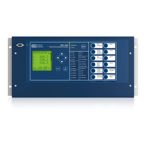
Page 220: Figure 5.1 Sel-421 Front Panel (8 Pushbutton Model)
U.5.2 Front-Panel Operations Front-Panel Layout Front-Panel Layout The front panel for the horizontal 3U (3 rack unit) SEL-421 configuration is shown in Figure 5.1 (other configurations are similar). Liquid Crystal Direct-Action Operation Display (LCD) Pushbuttons EIA-232 and Trip and Navigation... -
Page 221: Figure 5.3 Lcd Display And Navigation Pushbuttons
LED labels with the slide-in labels adjacent to the pushbuttons. The asserted and deasserted colors for the LEDs are programmable. The SEL-421 front panel includes an EIA-232 serial port (labeled PORT F) for ® connecting a communications terminal or using the... -
Page 222: Table 5.1 Front-Panel Inactivity Time-Out Setting
Front-panel display time-out OFF, 1–60 minutes 15 minutes Navigating the Menus The SEL-421 front panel presents a menu system for accessing metering, settings, and control functions. Use the LCD and the six pushbuttons adjacent to the display (see Figure 5.3) to navigate these front-panel menus. -
Page 223: Table 5.2 Metering Screens Enable Settings
Front-Panel Operations U.5.5 Front-Panel Layout Screen Scrolling The SEL-421 has two screen scrolling modes: autoscrolling mode and manual-scrolling mode. After front-panel time out, the LCD presents each of the display screens in this sequence: ➤ Any active (filled) alarm points screens ➤... -
Page 224: Figure 5.5 Sample Rotating Display
Alarm Points on page U.5.7). Each alarm points screen shows as DISPLAY many as 11 alarm conditions. The SEL-421 can present a maximum of 6 alarm points screens. The active display points are the second set of screens in the... -
Page 225: Figure 5.6 Sample Alarm Points Screen
To return to autoscrolling mode, press {ESC} or wait for a front-panel time out. Alarm Points You can display messages on the SEL-421 front-panel LCD that indicate alarm conditions in the power system. The relay uses alarm points to place these messages on the LCD. -
Page 226: Table 5.3 Ser Point Settings
While in the scrolling mode, the assertion of IN101 will cause Figure 5.6 to automatically display. Upon the deassertion of IN101, the asterisk will disappear, as in Figure 5.7. SEL-421 Relay User’s Guide Date Code 20090715 Courtesy of NationalSwitchgear.com... -
Page 227: Figure 5.7 Deasserted Alarm Point
Subsequent alarm point assertions will be displayed above the data loss message. ALARM POINTS ##SER DATA LOSS## Press to acknldge Figure 5.10 Alarm Points Data Loss Screen Date Code 20090715 User’s Guide SEL-421 Relay Courtesy of NationalSwitchgear.com... -
Page 228: Figure 5.11 Sample Display Points Screen
U.5.10 Front-Panel Operations Front-Panel Layout Display Points You can display messages on the SEL-421 front-panel LCD that indicate conditions in the power system. The relay uses display points to place these messages on the LCD. Figure 5.11 shows a sample display points screen. Display points can show the status of Relay Word bits or display the value of analog quantities. -
Page 229: Table 5.4 Display Point Settings-Boolean
A Phase Out=1234 MWHAOUT,“A Phase Out={3, 1000}” A Phase Out=$$$ kWh MWHAOUT,“A Phase Out={3, 1000} kWh” Fixed Text 1,“Fixed Text” Fixed Text 0,“Fixed Text” Empty Line Empty Line Display Point is hidden Date Code 20090715 User’s Guide SEL-421 Relay Courtesy of NationalSwitchgear.com... - Page 230 11 display points; this example demonstrates a method to set the display point messages that are shown in Figure 5.11. The SEL-421 in this example has an additional I/O interface board. This example is based on a three-pole circuit breaker, with breaker...
-
Page 231: Figure 5.12 Fast Meter Display Points Sample Screen
Figure 5.12 Fast Meter Display Points Sample Screen Front-Panel Menus and Screens Operate the SEL-421 front panel through a sequence of menus that you view on the front-panel display. The is the introductory menu for other MAIN MENU... -
Page 232: Figure 5.13 Contrast Adjustment
Passwords on page U.4.6 for more information on access levels and setting WARNING passwords. The SEL-421 front panel is at Access Level 1 upon initial power- This device is shipped with default up and after front-panel time out. passwords. Default passwords should be changed to private passwords at installation. -
Page 233: Figure 5.15 Invalid Password Screen
SET/SHOW RELAY STATUS VIEW CONFIGURATION DISPLAY TEST RESET ACCESS LEVEL Figure 5.16 MAIN MENU Meter The SEL-421 displays metering screens on the LCD. Highlight on the METER screen to select these screens. The , shown in MAIN MENU METER MENU Figure 5.17, allows you to choose the following metering screens... -
Page 234: Figure 5.18 Meter Submenu
METER SUBMENU breaker data that you want to display. For example, if you have two sources feeding a transmission line through two circuit breakers and you set ESS := 3, NUMBK := 2, then the SEL-421 measures currents, currents, and combined (Circuit... - Page 235 IC = x xxx.x IC = x xxx.xx +xxx˚ n = 1 or 2, representing Circuit Breaker 1 or Circuit Breaker 2, respectively. Figure 5.19 RMS, FUND, and DEMAND Metering Screens Date Code 20090715 User’s Guide SEL-421 Relay Courtesy of NationalSwitchgear.com...
- Page 236 Figure 5.20 ENERGY, MAX/MIN, and SYNCH CHECK Metering Screens Events The SEL-421 front panel features summary event reporting, which simplifies post-fault analysis. These summary event reports include all trip events, event and data capture triggering (via the ER SEL...
-
Page 237: Figure 5.22 Ser Events Screen
SER Events 001-003 Local Disabled 02/16/06 11:11:01.993 Local Enabled 02/16/06 10:11:19.090 IN101 Asserted 02/16/06 03:22:01.988 Figure 5.22 SER Events Screen If no SER events are available, Figure 5.23 is displayed. Date Code 20090715 User’s Guide SEL-421 Relay Courtesy of NationalSwitchgear.com... -
Page 238: Table 5.7 Front-Panel Pushbutton Functions While Viewing Ser Events
{Up Arrow} one more time and the report will wrap around to display the screen containing the last SER event. Breaker Monitor The SEL-421 features an advanced circuit breaker monitor. Select BREAKER screens from the to view circuit breaker monitor alarm... -
Page 239: Figure 5.25 Relay Elements Screen
Figure 5.24 BREAKER MONITOR Report Screens Relay Elements You can view the screen to check the state of the Relay Word RELAY ELEMENTS bits in the SEL-421. The relay has two unique manual-scrolling features for (Relay Word Bits) viewing these elements: ➤ Accelerated navigation ➤... -
Page 240: Figure 5.26 Element Search Screen
If the relay finds a match, ELEMENT SEARCH the screen displays the element row containing the matching element. Local Control The SEL-421 provides great flexibility in power system control through the menus. You can use the front-panel menus to LOCAL CONTROL... -
Page 241: Figure 5.27 Local Control Initial Menu
OPEN When you highlight the close option and press {ENT}, the relay displays the confirmation message and closes Circuit Breaker 1. CLOSE COMMAND ISSUED changes to BREAKER 1 STATUS CLOSED Date Code 20090715 User’s Guide SEL-421 Relay Courtesy of NationalSwitchgear.com... - Page 242 OGIC supervision. These local bits replace substation control handles to perform switching functions such as bus transfer switching. The SEL-421 saves the states of the local bits in nonvolatile memory and restores the local bit states at relay power-up.
-
Page 243: Figure 5.29 Local Control Example Menus
Figure 5.29 gives an example of a custom-labeled function, Bus Tie Interlock. The LCD shows a graphic representation of a substation control handle. The LB_DPnn SEL control equation determines the state of the OGIC switch position on the LCD. If the LB_DPnn Relay Word bit is deasserted, the graphic control handle points to 0;... -
Page 244: Table 5.8 Local Bit Control Settings
If an alias is too long, the relay displays Too many characters OGIC a Table 5.9 Local Bit SEL Description Range Default Local Bit Supervision n... -
Page 245: Figure 5.30 Local Bit Supervision Logic
Use the appropriate interface hardware to connect the circuit breaker interlock to OUT201. OUTPUT TESTING NOTE: The circuit breaker control You can check for proper operation of the SEL-421 control outputs by using enable jumper J18C must be installed submenu of the menu. A menu screen OUTPUT TESTING... -
Page 246: Table 5.10 Settings Available From The Front Panel
Figure 5.31 OUTPUT TESTING Screen Set/Show You can use the menus to examine or modify SEL-421 port settings, SET/SHOW global settings, active group settings, and date/time. From the front panel you can change only the settings classes and settings listed in Table 5.10. - Page 247 A B C D E F G H I J K L M N O P Q R S T U V W X ACCEPT BACKSPACE Figure 5.32 SET/SHOW Screens Date Code 20090715 User’s Guide SEL-421 Relay Courtesy of NationalSwitchgear.com...
- Page 248 The relay performs a password validation test at this point to confirm that you have Breaker Access Level authorization or above. Step 2. If access is allowed, and all the results of SEL control OGIC equations SS1–SS6 are not logical 1 (asserted), then the relay...
-
Page 249: Figure 5.34 Changing The Active Group
5.32) is the SET/SHOW DATE/ screen shown in Figure 5.35. The SEL-421 generates date and time TIME information internally, or you can use external high-accuracy time modes with time sources such as a GPS receiver. Figure 5.35 is the relay date/time screen when a high accuracy source is in use. - Page 250 Figure 5.36 Edit DATE and Edit TIME Screens To enable a high-accuracy external time source, connect an IRIG-B clock to the relay. For a discussion of the IRIG timing modes in the SEL-421 see Configuring High-Accuracy Timekeeping on page U.4.71. See TIME Input Connections on page U.2.45...
- Page 251 D20010307 BFID=SLBT-2701- R100-V0-Z000000- D20010307 CONFIGURATION INFO IF THE CONFIGURATION IS NOT WHAT YOU EXPECTED, CONTACT SEL FOR ASSISTANCE. Figure 5.38 VIEW CONFIGURATION Sample Screens Display Test You can use the option of the to confirm operation DISPLAY TEST MAIN MENU of all of the LCD pixels.
-
Page 252: Figure 5.40 Reset Access Level Screen
Figure 5.39 DISPLAY TEST Screens Reset Access Level The SEL-421 uses various passwords to control access to front-panel functions. As you progress through these menus, the relay detects the existing password level and prompts you for valid passwords before allowing you access to levels greater than Access Level 1 (see Password on page U.5.14... -
Page 253: Figure 5.41 Sample Status Warning, Alarm Point Assertion, And Trip Event Summary
Figure 5.41 Sample Status Warning, Alarm Point Assertion, and Trip EVENT SUMMARY Screens If you are on site using the SEL-421 front panel in menus and screens other than the and a status warning occurs, alarm point asserts, or an... -
Page 254: Figure 5.43 Factory Default Front-Panel Target Areas (16 Or 24 Leds)
The SEL-421 gives you at-a-glance confirmation of relay conditions via operation and target LEDs. These LEDs are located in the middle of the relay front panel. The SEL-421 provides either 16 or 24 LEDs depending on ordering option. You can reprogram all of these indicators except the ENABLED and TRIP LEDs to reflect other operating conditions than the factory default programming described in this subsection. -
Page 255: Table 5.11 Front-Panel Target Leds
LEDs (see Display Test on page U.5.33). Other Target Reset Options You can reset the target LEDs with the ASCII command TAR R; see TARGET on page R.9.50 for more information. Date Code 20090715 User’s Guide SEL-421 Relay Courtesy of NationalSwitchgear.com... -
Page 256: Table 5.12 Time Target Led Trigger Elements-Factory Defaults
EDRSTC := Y. Trip Type The SEL-421 indicates essential information about the most recent relay trip event with the LEDs of the Trip Type area. These trip types are INST, TIME, COMM, and SOTF. For information on setting the corresponding trip logic, see Trip Logic on page R.1.105. - Page 257 Zone 1, Zone 2, and Zone 3 did not operate. Phase(s) or Ground The phase(s) or ground targets illuminate according to the SEL-421 special targeting logic. This logic accurately classifies which phase, phases, and/or ground were involved in a trip event.
-
Page 258: Figure 5.44 Operator Control Pushbuttons And Leds (8 Or 12 Pushbuttons)
LEDs for local control. Figure 5.44 shows this region of the relay front panel with factory default configurable front-panel label text. The SEL-421 provides either 8 or 12 pushbuttons depending on ordering option. Annunciator LED Operator Control Pushbutton Figure 5.44 Operator Control Pushbuttons and LEDs (8 or 12 Pushbuttons) -
Page 259: Table 5.13 Operator Control Pushbuttons And Leds-Factory Defaults
LEDs with custom names to reflect any programming changes that you make. The labels are keyed; you can insert each Operator Control Label in only one position on the front of the relay. Included on the SEL-421 Relay Product Literature CD are word processor templates for printing slide-in labels. See the instructions included in the Configurable Label kit for more information on changing the slide-in labels. - Page 260 Front-Panel Operations Front-Panel Operator Control Pushbuttons The SEL-421 has two types of outputs for each of the front-panel pushbuttons. Relay Word bits represent the pushbutton presses. One set of Relay Word bits follows the pushbutton and another set pulses for one processing interval when the button is pressed.
-
Page 261: Figure 5.45 Factory Default Operator Control Pushbuttons
Press this operator control pushbutton to trip Circuit Breaker 1. The corresponding BREAKER PBn_LED BREAKER OPEN LED illuminates, indicating that Circuit Breaker 1 is open. OPEN = NOT 52ACL1 and 52BCL1 and 52CCL1 #BREAKER OPEN Figure 5.45 Factory Default Operator Control Pushbuttons Date Code 20090715 User’s Guide SEL-421 Relay Courtesy of NationalSwitchgear.com... - Page 262 This page intentionally left blank Courtesy of NationalSwitchgear.com...
-
Page 263: Table 6.1 Acceptance Testing
Each testing category includes particular details as to when to perform the test, the testing goals at that time, and the relay functions that you need to test. This information is a guide to testing the SEL-421; be sure to follow the practices of your company for relay testing. -
Page 264: Table 6.2 Commissioning Testing
Test all protection elements and logic functions critical to your intended application. Commissioning SEL performs a complete functional check and calibration of each SEL-421 before shipment so that your relay operates correctly and accurately. You Testing should perform commissioning tests to verify proper connection of the relay to the power system and all auxiliary equipment. -
Page 265: Table 6.3 Maintenance Testing
Test all relay features/power system components that did not operate during an actual fault within the past maintenance interval. You can use the SEL-421 reporting features as maintenance tools. Periodically compare the relay METER command output to other meter readings on a line to verify that the relay measures currents and voltages correctly and accurately. - Page 266 16 times per cycle, and the raw binary data (prior to debounce timer from 1 kHz to 8 kHz. You can use the SEL-5601 Analytic Assistant or other conditioning) is available in high- COMTRADE viewing program to export and view these raw data in a binary resolution oscillography—see...
- Page 267 MAP on page R.9.27). You must be familiar with the relay database structure to use the TEST DB command effectively; see Communications Card Database on page R.4.18 for more information. Date Code 20090715 User’s Guide SEL-421 Relay Courtesy of NationalSwitchgear.com...
- Page 268 You cannot directly test Fast Meter values that the relay derives from the reported values (power, sequence components, and so on). For more information on Fast Meter and the SEL-421, see Communications Protocols on page R.5.1.
-
Page 269: Table 6.4 Uut Database Entries For Sel-5401 Relay Test System Software-5 A Relay
Figure 6.1 Low-Level Test Interface Main Board Processing Module Tests Use signals from the SEL-4000 Low-Level Relay Test System to test the relay processing module. Apply appropriate signals to the low-level test interface J20 from the SEL-4000 Relay Test System (see Figure 6.1). -
Page 270: Table 6.5 Uut Database Entries For Sel-5401 Relay Test System Software-1 A Relay
Relay Test Connections NOTE: The procedures specified in The SEL-421 is a flexible tool that you can use to implement many protection this subsection are for initial relay and control schemes. Although you can connect the relay to the power system testing only. -
Page 271: Figure 6.2 Test Connections Using Three Voltage And Three Current Sources
You can use the connections shown Figure 6.3 to simulate phase-to-phase, phase-to-ground, and two-phase-to- ground faults. Use the connections shown in Figure 6.4 to simulate three- phase faults. Date Code 20090715 User’s Guide SEL-421 Relay Courtesy of NationalSwitchgear.com... -
Page 272: Figure 6.3 Test Connections Using Two Current Sources For Phase-To-Phase, Phase-To-Ground, And Two-Phase-To-Ground Faults
Relay Test Connections Three-Phase Voltage and Current Test Sources Relay Rear-Panel Secondary Voltage and Current Inputs Figure 6.3 Test Connections Using Two Current Sources for Phase-to-Phase, Phase-to-Ground, and Two-Phase-to-Ground Faults SEL-421 Relay User’s Guide Date Code 20090715 Courtesy of NationalSwitchgear.com... -
Page 273: Figure 6.4 Test Connections Using Two Current Sources For Three-Phase Faults
You can use the connections shown in Figure 6.5 to simulate phase-to-ground faults. Use the connections shown in Figure 6.6 to simulate phase-to-phase faults. Date Code 20090715 User’s Guide SEL-421 Relay Courtesy of NationalSwitchgear.com... -
Page 274: Figure 6.5 Test Connections Using A Single Current Source For A Phase-To-Ground Fault
Testing and Troubleshooting Relay Test Connections Three-Phase Voltage and Current Test Sources Relay Rear-Panel Secondary Voltage and Current Inputs Figure 6.5 Test Connections Using a Single Current Source for a Phase-to-Ground Fault SEL-421 Relay User’s Guide Date Code 20090715 Courtesy of NationalSwitchgear.com... -
Page 275: Figure 6.6 Test Connections Using A Single Current Source For A Phase-To-Phase Fault
Viewing a change in relay element (Relay Word bit) status is a good way to verify the pickup settings you have entered for protection elements. Date Code 20090715 User’s Guide SEL-421 Relay Courtesy of NationalSwitchgear.com... -
Page 276: Table 6.6 Phase Instantaneous Overcurrent Pickup
You will see the 50P1 element status change to 1 when the input current exceeds the 50P1P setting threshold. c. Type <Ctrl+X> to stop the relay from presenting the target display before completion of the 1000 target repeats. SEL-421 Relay User’s Guide Date Code 20090715 Courtesy of NationalSwitchgear.com... - Page 277 (see the first screen of Figure 6.8). RELAY ELEMENTS Step 3. Press the {ENT} pushbutton. You will see a screen (the second screen of RELAY ELEMENTS Figure 6.8). Date Code 20090715 User’s Guide SEL-421 Relay Courtesy of NationalSwitchgear.com...
-
Page 278: Figure 6.8 Viewing Relay Word Bits From The Front-Panel Lcd
Set the current output of a test source to zero output level. b. Connect a single-phase current output of the test source to the IAW analog input (see Figure 6.5 Secondary Circuits on page U.2.4). SEL-421 Relay User’s Guide Date Code 20090715 Courtesy of NationalSwitchgear.com... - Page 279 Elements on page R.1.64. In this example, use QuickSet to configure the relay. You must ERATOR have a computer that is communicating with the SEL-421 and running the QuickSet (see Making Settings Changes: Initial Global ERATOR Settings on page U.4.17). In addition, you need a variable current source suitable for relay testing.
-
Page 280: Figure 6.10 Uploading Front-Panel Settings To The Sel-421
For this test, you must have a computer with QuickSet for the ERATOR SEL-421, a variable current source for relay testing, and a control output closure indicating device such as a test set or a VOM (volt ohmmeter). SEL-421 Relay User’s Guide... - Page 281 Testing and Troubleshooting U.6.19 Test Methods In this example, use QuickSet to configure the relay. You must ERATOR have a computer that is communicating with the SEL-421 and running QuickSet (see Making Settings Changes: Initial Global ERATOR Settings on page U.4.17).
-
Page 282: Figure 6.12 Uploading Output Settings To The Sel-421
You can set the relay to generate a report from the SER to test relay elements; include the element that you want to test in the SER Points and Aliases list. Set aliases for the element name, set state, and clear state in the SEL-421 SER to simplify reading the SER report. See SER (Sequential Events Recorder) on page A.3.34... -
Page 283: Table 6.7 Selectable Operating Quantity Time-Overcurrent Element (51S1) Default Settings
Elements on page R.1.70. In this example, use QuickSet to configure the relay. You must ERATOR have a computer that is communicating with the SEL-421 and running the QuickSet (see Making Settings Changes: Initial Global ERATOR Settings on page U.4.17). You also need a variable current source for relay testing. - Page 284 Click the button beside the Relay Word bit entry field. c. Select Overcurrent Element Bits. d. Double-click on 51S1T to copy the name into the Relay Word Bit field. SEL-421 Relay User’s Guide Date Code 20090715 Courtesy of NationalSwitchgear.com...
-
Page 285: Figure 6.15 Uploading Group 1 And Report Settings To Sel-421
Automation 2 through Automation 10 setting instances. Figure 6.15 Uploading Group 1 and Report Settings to SEL-421 Step 7. Connect a test source to the relay. a. Set the current output of a test source to zero output level. - Page 286 ERATOR Checking Relay Operation The SEL-421 comes to you with all functions fully checked and calibrated so that the relay operates correctly and accurately. You can perform tests on the relay to verify proper relay operation, but you do not need to test every relay element, timer, and function in this evaluation.
- Page 287 Phase Overcurrent Elements The SEL-421 phase overcurrent elements compare the phase current applied to the secondary current inputs with the phase overcurrent element pickup setting. The relay asserts the phase overcurrent elements when any of the three phase currents exceeds the corresponding element pickup setting.
- Page 288 Testing and Troubleshooting Checking Relay Operation Ground Overcurrent Elements The SEL-421 ground overcurrent elements compare a residual ground calculation of the three-phase inputs with the residual overcurrent setting. The relay makes this residual current calculation: = A-phase + B-phase + C-phase...
-
Page 289: Figure 6.18 Negative-Sequence Instantaneous Overcurrent Element Settings
Figure 6.18 Negative-Sequence Instantaneous Overcurrent Element Settings: QuickSet ERATOR Step 2. Upload the new setting to the SEL-421. a. Click File > Send. QuickSet prompts you for the settings ERATOR class you want to send to the relay, as shown in the... -
Page 290: Figure 6.20 Element Search Screen
You will see that the 50Q1 element state changes on the LCD screen from 50Q1 = 0 to 50Q1 = 1. Negative-Sequence The SEL-421 features a phase directional element (represented by Relay Word bits F32P/R32P) to supervise the phase distance elements and to control phase Directional Element directional elements. - Page 291 For more information on the directional elements, see Ground Directional Element on page R.1.27 Quadrilateral Ground Distance Elements on page R.1.54. For settings and application information, see Section 1: Protection Application Examples in the Applications Handbook. Date Code 20090715 User’s Guide SEL-421 Relay Courtesy of NationalSwitchgear.com...
- Page 292 ERATOR Step 1. Configure the relay. a. Open QuickSet and read the present ERATOR configuration in the SEL-421. b. Click Settings > Read. The relay sends all settings and configuration data to QuickSet. ERATOR c. Expand the Group 1 settings and click the Relay...
-
Page 293: Figure 6.23 Breaker 1 Breaker Monitor Settings: Ac Sel Erator Quickset
E32 is set to AUTO. f. If you need to change these settings, set E32 to Y. Table 6.8 shows the calculations. Ground Directional Element on page R.1.27 details on these relay calculations. Date Code 20090715 User’s Guide SEL-421 Relay Courtesy of NationalSwitchgear.com... -
Page 294: Table 6.8 Negative-Sequence Directional Element Settings Auto Calculations
QuickSet ERATOR Table 6.8 Negative-Sequence Directional Element Settings AUTO Calculations Setting Calculation 50FP 0.12 • I 50RP 0.08 • I 0.5 • Z1MAG Z2F + 1 / (2 • I SEL-421 Relay User’s Guide Date Code 20090715 Courtesy of NationalSwitchgear.com... - Page 295 Automation 2 through Automation 10 setting instances. Figure 6.26 Uploading Group 1 and Breaker Monitor Settings to the SEL-421 Step 4. Display the F32Q and R32Q Relay Word bits on the front- panel LCD screen.
- Page 296 Be sure to satisfy all the element supervisory conditions before testing a relay element. For supervisory conditions for a particular element, see Mho Ground Distance Elements on page R.1.49. SEL-421 Relay User’s Guide Date Code 20090715 Courtesy of NationalSwitchgear.com...
- Page 297 The relay has phase distance elements to detect phase-to-phase faults, phase-to-phase-to-ground faults, and three-phase faults. The SEL-421 has five independent zones of mho phase distance protection; each zone consists of phase-to-phase elements that the relay combines to produce a particular zone output.
- Page 298 The relay measures phase distance element maximum reach when the faulted phase-to-phase current lags the faulted phase-to-phase voltage by the distance element maximum torque angle. In the SEL-421, the phase distance element maximum torque angle is setting Z1ANG. Current I should lag voltage V by Z1ANG.
- Page 299 9.36. Figure 6.29 Phase Distance Elements Settings: QuickSet ERATOR Step 4. Upload the new settings to the SEL-421. a. Click File > Send. QuickSet prompts you for the settings ERATOR class you want to send to the relay, as shown in the...
- Page 300 Z2P reach setting. Relay Self-Tests The SEL-421 continuously runs many self-tests to detect out-of-tolerance conditions. These tests run at the same time as relay protection and automation logic, but do not degrade SEL-421 performance.
- Page 301 The relay signals a status warning by pulsing the HALARM Relay Word bit (hardware alarm) to logical 1 for five seconds. For a Status Failure, the relay latches the HALARM Relay Word bit at logical 1. SEL-421 relays will restart on certain diagnostic failures. When this occurs, the relay will log a...
- Page 302 Active High Accuracy Time Synchronization Source: IRIG-B IRIG-B Source PRESENT SELogic Relay Programming Environment Errors No Errors Relay Enabled =>> Figure 6.32 Relay Status From a STATUS A Command on a Terminal SEL-421 Relay User’s Guide Date Code 20090715 Courtesy of NationalSwitchgear.com...
- Page 303 (description) is text that the relay supplies ➤ (Ok or W or F) is normal, warning, or failure, respectively Figure 6.34 is a sample Compressed ASCII status message. =>CST <Enter> "RID","SID","FID","03e2" "Relay 1","Station A","SEL-421-R101-V0-Z001001-D20010315","0e06" "MONTH","DAY","YEAR","HOUR","MIN","SEC","MSEC","0ACA" 3,15,2001,13,2,26,938,"0437" "CPU_RAM","CPU_Prog","SELBOOT","CPU_Settings","DSP_RAM","DSP","DSP_Chksum","DSP_ TIMEOUT","CPU_CARD_RAM","CPU_DSP_RAM","FRONT_PANEL","CAL_BOARD","Comm_Card","Com m_Card_Code","QUART","Analog_Conv","IO_1","IO_2","3B86" "Ok","Ok","Ok","Ok","Ok","Ok","Ok","Ok","Ok","Ok","Ok","Ok",,,"Ok","Ok","Ok","Ok ","12F8"...
-
Page 304: Table 6.9 Troubleshooting Procedures
Table 6.9. The table lists each symptom, possible causes, and corresponding diagnoses/ Procedures solutions. Related SEL-421 commands are listed in bold capitals. See Section 9: ASCII Command Reference in the Reference Manual for details on SEL-421 commands and Section 10: Settings in the Reference Manual details on relay settings. - Page 305 Possible Cause Diagnosis/Solution Other self-test failure. LCD displays STATUS FAILURE screen. Contact the SEL factory or your Technical Service Center. System Does Not Respond to Commands No communication. Confirm cable connections and types. If correct, type <Ctrl+X> <Enter>. This resets the terminal program.
- Page 306 Reseat both ends of the analog input cable. ule board and the main board. A/D converter drift. Log the Status Warning. If repeated warn- ings occur, contact the SEL factory or your Technical Service Center. Master offset drift. LCD displays STATUS FAILURE screen.
- Page 307 Testing and Troubleshooting U.6.45 Factory Assistance Factory Assistance We appreciate your interest in SEL products and services. If you have any questions or comments, please contact us at: Schweitzer Engineering Laboratories, Inc. 2350 NE Hopkins Court Pullman, WA 99163-5603 USA Phone: +1.509.332.1890...
- Page 308 This page intentionally left blank Courtesy of NationalSwitchgear.com...
-
Page 309: Table A.1 Firmware Revision History
STATUS command. The status report displays the Firm- Firmware Version in ware Identification (FID) label: Your Relay FID=SEL-421-Rxxx-Vx-Zxxxxxx-Dxxxxxxxx, or FID=SEL-421-x-Rxxx-Vx-Zxxxxxx-Dxxxxxxxx You can also view the FID label from the front panel. From the ROTATING front-panel screen, press the {ENT} pushbutton to advance to the... - Page 310 SEL-421-1-R201-V0-Z007007-D20070220 ➤ SEL-421-2-R123-V0-Z010010-D20070223 Ethernet card firmware (see Table A.2) and manual update only 20070914 (see Table A.5). SEL-421-3-R123-V0-Z010010-D20070223 ➤ SEL-421-2-R123-V0-Z010010-D20070223 Manual update only (see Table A.5). 20070717 SEL-421-3-R123-V0-Z010010-D20070223 SEL-421-R201-V0-Z007007-D20070220 SEL-421-1-R201-V0-Z007007-D20070220 SEL-421 Relay User’s Guide Date Code 20090715 Courtesy of NationalSwitchgear.com...
- Page 311 Added new DNP setting MAPSEL and implemented extended binary input map. ➤ Implemented DNP single-event mode. ➤ Increased number of SEL conditional timers from 16 to 32. OGIC ➤ Decreased LOP latching delay from 60 cycles to 15 cycles. ➤...
- Page 312 Table A.1 Firmware Revision History (Sheet 4 of 9) Manual Firmware Identification (FID) Number Summary of Revisions Date Code SEL-421-2-R118-V0-Z008008-D20060630 Note: Firmware version R118 and newer are not applicable to the SEL- 20060703 421 and SEL-421-1. SEL-421-3-R118-V0-Z008008-D20060630 ➤ Corrected IG magnitude and angle calculations in the CEV summary report.
- Page 313 The STATUS A command will now include information on how many Telnet sessions are active. ➤ Added second file transfer session to allow access to SEL-2701 settings files (SET_DNPn.TXT) via FTP. ➤ Fixed the Trip Unlatch logic to ignore 52AA2 logic when NUMBK =1.
- Page 314 SEL-421-1-R112-V0-Z004005-D20041217 ➤ Added support for IEEE C37.118, Standard for Synchrophasors for Power Systems. ➤ Added Synchrophasor support to the SEL-421-1. ➤ Added PMU (Phasor Measurement Unit) to the serial port settings protocol (PROTO) options for dedicated synchrophasor communications. ➤...
- Page 315 Corrected issue where incorrect scaling of stored values could cause an erroneous drift in the metered slip frequency for synchronism check. ➤ Added Security Enhancements when used with the SEL-2701 Ethernet Processor. ➤ SEL-421-R111-V0-Z003004-D20040602 Corrected issue where turning off power may cause a low-set...
- Page 316 ➤ Corrected file command error message. ➤ Fixed condition where the SEL-421 does not send the fast message power-up bit in the status byte of the first message. ➤ Fixed condition in R109 where a file read of events or compressed history using the no modem option may cause the relay to become non-responsive.
-
Page 317: Table A.2 Ethernet Card Firmware Revision History
This condition occurs when a communications processor SEL-421-1-R103-V0-Z002002-D20020417 is automatically retrieving data from the relay simultaneously with a serial port terminal session. ➤ SEL-421-R102-V0-Z002001-D20020403 Added new analog quantities for use in the following SEL 20020403 OGIC control equations: SEL-421-1-R102-V0-Z002001-D20020403 Terminal W and X current magnitudes... -
Page 318: Table A.3 Compatible Sel-421 And Ethernet Card Firmware Versions
Look for the Ethernet card Firmware Identification (FID) label in the response under Communications Card: FID=SEL-270x-Rxxx-Vx-Zxxxxxx-Dxxxxxxxx In the FID label, the 4 digits after “SEL” indicate which Ethernet card is installed. The firmware revision number follows the R and the release date fol- lows the D. - Page 319 If you perform an Ethernet card firmware upgrade that spans different file ver- sion compatibilities, the relay may not be able to process the stored CID file. See the Ethernet Port Firmware Upgrade Instructions in the SEL-400 Series Firmware Upgrade Instructions for CID file conversion procedures.
- Page 320 Updated Changing the Default Passwords to add Access Level C information. ➤ Updated Figure 4.5: Access Level Structure. ➤ Updated Table 4.3: SEL-421 Access Levels and Table 4.4: SEL-421 Access Level Commands and Passwords. ➤ Updated Communications Ports Access Levels to reflect new Access Level C port settings. ➤...
- Page 321 Added Relay Word bits: Local Bit Supervision and Status table for rows 284–291 to Table A.53. 20070223 User’s Guide Appendix A ➤ Updated for firmware version R123 (SEL-421-2, -3) and R201 (SEL-421-0, -1). Applications Handbook Section 6 ➤ Added LED and pushbutton statuses from expanded HMI to Table 6.7.
- Page 322 Added Alias Settings and Auxiliary Pushbuttons to Features. ➤ Added INT3 to Models and Options. ➤ Added INT3 to SEL-421 Versions and Supported Features. ➤ Added INT3 and Auxiliary {TRIP}/{CLOSE} Pushbuttons to Specifications. Section 2 ➤ Added INT3 to Control Inputs.
- Page 323 Updated Figure 6.2 for new setting MAPSEL. ➤ Updated Table 6.18 for new settings EVELOCK, MINDIST, and MAXDIST. Section 9 ➤ Added SET T and SHO T commands. ➤ Updated TAR command to include aliases. Date Code 20090715 User’s Guide SEL-421 Relay Courtesy of NationalSwitchgear.com...
- Page 324 In Status Warning and Status Failure added information about the relay restarting on certain diagnostic failures. Appendix A ➤ Updated for firmware version R121 (SEL-421-2, -3) and R200 (SEL-421-0, -1). Applications Handbook Section 3 ➤ Added diagnostic restart to the list of conditions captured by the SER.
- Page 325 Moved cautions, warnings, and dangers in English and French from reverse of front cover to the Preface. User’s Guide Section 1 ➤ Added a table distinguishing the versions of the SEL-421. ➤ Added information about Main Board A and Main Board B and interface boards INT2, INT7, and INT8. Date Code 20090715 User’s Guide...
- Page 326 Modified Figure 6.9 to update for new front-panel settings categories. ➤ Modified Figure 6.14 to reflect new SER setting parameter HMI Alarm. Command Summary ➤ Added footnote explaining that the SEL-421-1 and SEL-421-2 have only one instance of automation logic settings. Applications Handbook Section 1 ➤...
- Page 327 Added a row (15 option to the range of MRATE in the Global setting class) to Table 7.11. ➤ Corrected typographical errors. ➤ Corrected footnote to Table 7.16. Section 9 ➤ Corrected typographical errors. ➤ Corrected Table 9.113. Date Code 20090715 User’s Guide SEL-421 Relay Courtesy of NationalSwitchgear.com...
- Page 328 Modified Figure 2 13 title (added “E79 := Y”). ➤ Modified Figure 2 15 title (added “E79 := Y”). ➤ Updated E79 entries in Table 2 19 and Table 2 20. SEL-421 Relay User’s Guide Date Code 20090715 Courtesy of NationalSwitchgear.com...
- Page 329 Updated rear-panel figures and related text to show new TIME input configuration. ➤ Removed Front-Panel Labels—the configurable label instructions are now in a separate package included with the relay. Section 3 ➤ Updated SEL-5030 screen captures and related text. ERATOR Section 4 ➤ Updated SEL-5030 screen captures and related text. ERATOR ➤...
- Page 330 Updated Table 4.1 and Figure 4.2. Section 5 ➤ Updated Table 5.2. ➤ Added Automatic Messages and Timeout subsections to describe these features already in the SEL-421. ➤ Removed Fast Message Synchrophasor information—now covered in Section 7. Section 6 ➤...
- Page 331 Changed quantity of free-form protection SEL OGIC ➤ Updated Table 3.6, Table 3.7, and Table 3.8. Section 5 ➤ Added new section on using the SEL-2600A RTD module. Section 9 ➤ Added OFF to the XC setting range. Appendix A ➤...
- Page 332 Table A.5 Instruction Manual Revision History (Sheet 14 of 16) Revision Date Summary of Revisions Reference Manual Section 1 ➤ Added NAND gates (SPOA, SPOB, and SPOC) at the DTA, DTB, and DTC SEL Settings inputs in OGIC Figure 1.60, Trip During Pole Open to TPA. Section 3 ➤...
- Page 333 Added VAZ, VBZ, VCZ settings options to SYNCP. ➤ Added VAY, VBY, VCY settings options to SYNCS1, SYNCS2 and ASYNCS2. ➤ Added ACOS, ASIN, CEIL, FLOOR and LOG math functions to SEL control equations. OGIC ➤ Added new analog quantities for use in SEL...
- Page 334 Added Notes to flag the differences in the SEL-421-1 Relay. Appendix A ➤ Added Notes to flag the differences in the SEL-421-1 Relay. Index ➤ Added index entries for configurable front-panel labels, SEL-421-1 Relay, and series-compensated line. 20010703 Initial version. SEL-421 Relay User’s Guide Date Code 20090715...
- Page 335 The designation of the vertical height of a device in rack units. One rack unit, U, is approximately 1.75 inches or 44.45 mm. Abbreviation for amps or amperes; unit of electrical current flow. ® ABS Operator An operator in math SEL control equations that provides absolute OGIC value. AC Ripple The peak-to-peak ac component of a signal or waveform.
- Page 336 Defines a set of objects, a set of services to manipulate and access those objects, and a base set of data types for describing objects. Active Settings Group The settings group that the SEL-421 is presently using from among six settings groups available in the relay. Admittance The reciprocal of impedance;...
- Page 337 To activate. To fulfill the logic or electrical requirements needed to operate a device. To set a logic condition to the true state (logical 1) of that condition. To apply a closed contact to an SEL-421 input. To close a normally open output contact. To open a normally closed output contact.
- Page 338 Bandpass Filter A filter that passes frequencies within a certain range and blocks all frequencies outside this range. Best Choice Ground An SEL logic that determines the directional element that the relay uses for Directional Supervision™ ground faults. logic Bit Label The identifier for a particular bit.
- Page 339 IEC 61850 Configured IED Description file. XML file that contains the configuration for a specific IED. Circuit Breaker This logic within the SEL-421 detects and warns of failure or incomplete Failure Logic operation of a circuit breaker in clearing a fault or in performing a trip or close sequence.
- Page 340 Relay outputs that affect the state of other equipment. Connect control outputs to circuit breaker trip and close coils, breaker failure auxiliary relays, communications-assisted tripping circuits, and SCADA systems. COS Operator Operator in math SEL control equations that provides the cosine OGIC function.
- Page 341 To clear a logic condition to its false state (logical 0). To open the circuit or open the contacts across an SEL-421 input. To open a normally open output contact. To close a normally closed output contact.
- Page 342 Electrical standard for multidrop serial data communications interfaces, based on the standard EIA/TIA-485. Formerly known as RS-485. Electrical Operating Time Time between trip or close initiation and an open phase status change. SEL-421 Relay Date Code 20090715 Courtesy of NationalSwitchgear.com...
- Page 343 Unlike the hybrid control output, this output is not polarity sensitive; reversed polarity causes no misoperations. Fast Meter SEL binary serial port command used to collect metering data with SEL relays. Fast Operate SEL binary serial port command used to perform control with SEL relays.
- Page 344 GL.10 Glossary Fast Message—GOOSE Fast Message SEL binary serial port protocol used for Fast SER, Fast Message Synchrophasors, and RTD communications. Fault Type Logic the relay uses to identify balanced and unbalanced faults (FIDS). Identification Selection Relay firmware identification string. Lists the relay model, firmware version and date code, and other information that uniquely identifies the firmware installed in a particular relay.
- Page 345 IA, IB, IC Measured A-phase, B-phase, and C-phase currents. ICD File IEC 61850 IED Capability Description file. XML file that describes IED capabilities, including information on logical node and GOOSE support. Date Code 20090715 SEL-421 Relay Courtesy of NationalSwitchgear.com...
- Page 346 (Group 1–Group 6), while the Global settings class has one instance. Instantaneous Meter Type of meter data presented by the SEL-421 that includes the present values measured at the relay ac inputs. The word “Instantaneous” is used to differentiate these values from the measurements presented by the demand, thermal, energy, and other meter types.
- Page 347 Maximum/Minimum Type of meter data presented by the SEL-421 that includes a record of the Meter maximum and minimum of each value, along with the date and time that each maximum and minimum occurred.
- Page 348 Nonhomogeneous System A power system with a large angle difference (>5° difference) for the impedance angles of the local source, the protected line, and the remote source. SEL-421 Relay Date Code 20090715 Courtesy of NationalSwitchgear.com...
- Page 349 Peak Demand Metering Maximum demand and a time stamp for phase currents, negative-sequence and zero-sequence currents, and powers. The SEL-421 stores peak demand values and the date and time these occurred to nonvolatile storage once per day, overwriting the previously stored value if the new value is larger. Should the relay lose control power, the relay restores the peak demand information saved at 23:50 hours on the previous day.
- Page 350 The cosine of the angle by which phase current lags or leads phase voltage in an ac electrical circuit. Power factor equals 1.0 for power flowing to a pure resistive load. Pulse per second from a GPS receiver. Previous SEL-421 relays had a TIME 1k PPS input. Protection and Segregation of protection and automation processing and settings.
- Page 351 1 or logical 0. Logical 1 represents a true logic condition, picked up element, or asserted control input or control output. Logical 0 represents a false logic condition, dropped out element, or deasserted control input or control output. Use Relay Word bits in SEL control equations. OGIC...
- Page 352 GOMSFE models and data within the IED. Self-Test A function that verifies the correct operation of a critical device subsystem and indicates detection of an out-of-tolerance condition. The SEL-421 has self-tests that validate the relay power supply, microprocessor, memory, and other critical systems.
- Page 353 Shunt Current The current that a parallel-connected high-resistance or high-impedance device diverts away from devices or apparatus. SIN Operator Operator in math SEL control equations that provides the sine function. OGIC Single-Pole Trip A circuit breaker trip operation that occurs when one pole of the three poles of a circuit breaker opens independently of the other poles.
- Page 354 All faults that do not include all three phases of a system. Unbuffered Report IEC 61850 IEDs can issue immediate unbuffered reports of internal events (caused by trigger options data-change, quality-change, and data-update) on a SEL-421 Relay Date Code 20090715 Courtesy of NationalSwitchgear.com...
- Page 355 (3I Zero-Sequence A factor based on the zero-sequence and positive-sequence impedance of a Compensation Factor line that modifies a ground distance element to have the same reach as a phase distance element. Date Code 20090715 SEL-421 Relay Courtesy of NationalSwitchgear.com...
- Page 356 QuickSet software relay driver version and HMI driver version when creating or editing relay settings files. Zone Time Delay Time delay associated with the forward or reverse step distance and zone protection. SEL-421 Relay Date Code 20090715 Courtesy of NationalSwitchgear.com...
- Page 357 Telnet U.3.5 Restoration R.9.4 terminal U.3.5 Automessages U.6.39 A.6.6 R.5.8 BREAKER CONTROL COMTRADE U.3.16 – U.3.20 See also SEL Binary Protocols – front panel U.5.23 U.5.24 control window U.3.22 Auto-Reclose R.2.1 – R.2.41 U.3.6 – U.3.8 Breaker Failure Protection database manager –...
- Page 358 R.9.40 – R.9.44 – R.1.87 R.1.104 A.1.152 – A.1.158 SHOW R.9.44 See also DCB; DCUB; POTT – Scheme 2 R.1.117 R.1.119 – – STATUS U.6.39 U.6.40 R.9.48 R.1.88 – R.1.91 R.9.49 SEL-421 Relay Date Code 20090715 Courtesy of NationalSwitchgear.com...
- Page 359 U.2.8 terminal blocks U.2.2 logic diagram R.1.41 diagram U.2.8 Contact Card ratings U.2.8 See SEL Contact Card I/O, Main Board A and Main Board Data Contact Inputs U.2.10 U.2.15 filtered data A.3.2 See Control Inputs INT1, INT2, INT4, INT5, INT6, high-resolution raw data A.3.2...
- Page 360 A.3.25 – R.4.16 Directional Overcurrent Elements A.3.28 MEMORY R.4.17 See Overcurrent Elements currents and voltages A.3.15 PING R.4.17 Display QUIT R.4.12 R.4.17 See LCD, Front Panel STATUS R.4.18 summary R.4.10 SEL-421 Relay Date Code 20090715 Courtesy of NationalSwitchgear.com...
- Page 361 – History Report Factory Assistance U.6.45 U.5.22 circuit breaker A.2.2 Fast Message RELAY STATUS U.5.32 See also Circuit Breaker‚ history See SEL Binary Protocols RESET ACCESS LEVEL U.5.34 report Fast Meter – U.5.19 U.5.20 event A.3.31 See SEL Binary Protocols –...
- Page 362 A.1.92 password jumper U.2.18 – U.2.20 See Trip Logic high-speed elements R.1.58 – serial port U.2.21 U.2.22 – Maximum/Minimum Metering A.2.31 – logic diagrams R.1.59 R.1.61 A.2.33 See also Meter accuracy A.2.32 SEL-421 Relay Date Code 20090715 Courtesy of NationalSwitchgear.com...
- Page 363 A.1.130 Passwords R.4.11 trip-on-way-out A.1.130 Protection and Automation Separation PC Software R.3.3 tripping, OOST U.1.3 R.1.43 QuickSet ERATOR See also SEL Control Software OGIC application example A.1.127 – Equations A.1.134 Permissive Overreaching Transfer Trip Pulsar Modem Output SEL Control Equations...
- Page 364 – A.4.4 access levels R.4.11 zero-sequence compensation R.1.54 variables R.3.13 passwords R.4.11 QUIT Command R.9.37 Sequential Events Recorder SEL Binary Protocols R.4.2 R.5.2 See SER (Sequential Events Fast Message Synchrophasor R.7.31 Recorder) Fast Meter A.6.6 R.5.8 R.9.2 – Rack Mount U.2.30...
- Page 365 U.5.31 R.9.17 timing diagram A.5.3 System Integration A.6.1 from front panel U.4.28 – U.4.32 – Substation Automation R.3.2 U.5.28 U.5.32 See also SEL Control – application example U.4.28 OGIC TARGET Command U.6.5 R.9.50 – – Equations U.4.30 U.4.30 U.4.32 R.9.51 –...
- Page 366 R.1.106 Time Inputs U.2.11 U.2.45 trip Relay Word bits R.1.108 See also IRIG-B trip timers A.1.13 – A.1.14 A.1.40 connecting U.4.73 A.1.78 A.1.110 R.1.107 IRIG-B U.2.11 TDUR1D and TDUR3D R.1.107 TOPD R.1.107 SEL-421 Relay Date Code 20090715 Courtesy of NationalSwitchgear.com...
- Page 367 SEL-421 Relay Command Summary Command Description 2ACCESS Go to Access Level 2 (complete relay monitoring and control) AACCESS Go to Access Level A (automation control) ACCESS Go to Access Level 1 (monitor relay) BACCESS Go to Access Level B (monitor relay and control circuit breakers)
- Page 368 Communications port settings Report Event report and SER settings Alias Alias names for analog quantities and Relay Word bits The SEL-421-1 and the SEL-421-2 have only one instance of automation logic settings. SEL-421 Relay Date Code 20090715 Courtesy of NationalSwitchgear.com...
- Page 369 SEL-421 Relay Command Summary Command Description 2ACCESS Go to Access Level 2 (complete relay monitoring and control) AACCESS Go to Access Level A (automation control) ACCESS Go to Access Level 1 (monitor relay) BACCESS Go to Access Level B (monitor relay and control circuit breakers)
- Page 370 Communications port settings Report Event report and SER settings Alias Alias names for analog quantities and Relay Word bits The SEL-421-1 and the SEL-421-2 have only one instance of automation logic settings. SEL-421 Relay Date Code 20090715 Courtesy of NationalSwitchgear.com...
Need help?
Do you have a question about the 421 and is the answer not in the manual?
Questions and answers