Table of Contents
Advertisement
Available languages
Available languages
Quick Links
Download this manual
See also:
User Manual
Advertisement
Table of Contents

Related Manuals for Lumel N43


Summary of Contents for Lumel N43
- Page 1 MIERNIK PARAMETRÓW SIECI NA SZYNĘ RAIL MOUNTED POWER NETWORK METER INSTRUKCJA OBSŁUGI SZYBKI START USER’S MANUAL QUICK START Zeskanuj mnie Zeskanuj kod Scan the code Pełna wersja instrukcji dostępna na Full version of user’s manual available at www.lumel.com.pl...
- Page 2 1. WYMAGANIA PODSTAWOWE, BEZPIECZEÑSTWO U¯YTKOWANIA W zakresie bezpieczeństwa użytkowania odpowiada wymaganiom normy PN-EN 61010-1. Uwagi dotyczące bezpieczeństwa: • Instalacji i podłączeń miernika powinien dokonywać wykwalifi kowany personel. Należy wziąć pod uwagę wszystkie dostępne wymogi ochrony. • Przed włączeniem miernika należy sprawdzić poprawność połączeń. •...
- Page 3 (np. kolejnymi miernikami N43). Należy zachować minimalny odstęp pomiędzy urządzeniami min 5 mm w celu umożli- wienia odpromieniowania ciepła od obudów urządzeń do otoczenia. W przeciwnym razie temperatura otoczenia pracującego w bezpośred- nim kontakcie z innymi urządzeniami miernika może przekroczyć tem- peraturę...
-
Page 4: Schematy Podłączeń
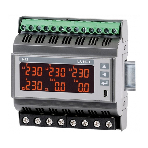
3. OPIS PRZYRZ¥DU 3.1 Wejścia prądowe Wszystkie wejścia prądowe są izolowane galwanicznie (wewnętrzne przekładniki prądowe). Miernik przystosowany jest do podłączeń bezpośrednich /do 63 A/ lub do współpracy z zewnętrznymi przekład- nikami prądowymi /w wykonaniu na 1 A/5 A /. Wyświetlane wartości prądów i wielkości pochodnych automatycznie przeliczane są... - Page 5 4. PROGRAMOWANIE N43 4.1 Panel przedni Rys 3. Panel przedni.
-
Page 6: Opis Panelu Przedniego
Opis panelu przedniego: przycisk zwiększania wartości przesunięcia eksport energii czynnej w prawo przycisk zmniejszania wartości przesunięcia import energii czynnej w lewo symbol energii / mocy przycisk akceptacji ENTER biernej indukcyjnej symbol energii / mocy gniazdo USB biernej pojemnościowej 6 pól wyświetlaczy 3-cyfro- symbol wyjścia impulso- wych do odczytów i usta- f1...f6... - Page 7 Rys 4. Komunikat po uruchomienia miernika. Po włączeniu zasilania miernik wykonuje test wyświetlacza i wyświetla nazwę miernika N43, wykonanie oraz aktualną wersję programu i bootloadera. gdzie: n43 – typ miernika, 5A 230V – rodzaj wykonania rEu rewizja 0.10 nr wersji programu b0.00 nr wersji bootloadera...
-
Page 8: Tryby Pracy
T ryb P O M IA R o zn a cza lu b Podane tablice znajdują się > w pełnej instrukcji obsługi - se k je d n o cze sn e n a ciśn ię cie p rzyciskó w dostępnej na www.lumel.com.pl... - Page 9 4.4 Tryb POMIAR W trybie Pomiar wyświetlane są wartości wielkości wg stron zaprogramowanych fabrycznie lub skonfi gurowanych przez użytkowni- ka w trybie Programowanie stron PAG. Zmiana strony dokonuje się przez naciśnięcie przycisku . Kolejność wyświetlanych stron wg tablicy utworzonej w trybie PAG.
- Page 10 Rys 6. Formaty wyświetlanych wartości Przekroczenie górnego lub dolnego zakresu wskazań sygnalizowane jest na wyświetlaczu górnymi poziomymi kreskami. W przypadku pomiaru wielkości uśrednionych (P Demand,S Demand, I Demand) pojedyncze pomiary wykonywane są z kwantem 1 sekundowym, jednak wizualizowane co 15 sekund. Czas uśredniania do wyboru: 15, 30 lub 60 minut.
- Page 11 Wybór wielkości monitorowanej: Tablica 1 Brak wielkości -wyświet- √ √ f1,f2,f3,f4,f5,f6 lacz wygaszony 01 Napięcie fazy L1 (k)V √ Prąd w przewodzie fazo- (k)A √ √ wym L1 03 Moc czynna fazy L1 (M,k)W √ 04 Moc bierna fazy L1 (M,k)VAr √...
- Page 12 12 Moc czynna fazy L2 (M,k)W √ (M,k)VAr √ 13 Moc bierna fazy L2 √ 14 Moc pozorna fazy L2 (M,k)VA Współczynnik mocy √ czynnej fazy L2 (PF2=P2/S2) Współczynnik tgϕ fazy √ L2 (tg2=Q2/P2) 17 THD napięcia fazy L2 √...
- Page 13 Współczynnik tgϕ √ √ ΣL f1,f2,f3,f4 3-fazowy średni (tg=Q/P) √ √ 34 Częstotliwość ΣL Napięcie międzyfazowe (k)V L1 L2 √ √ L1-L2 Napięcie międzyfazowe (k)V L2 L3 √ √ L2-L3 Napięcie międzyfazowe √ √ (k)V L3 L1 ...
-
Page 14: Ustawienia Parametrów
W przypadku wprowadzenia błędnego kodu dostępu możliwy jest tylko podgląd parametrów bez możliwości ich zmian. Wyświetlany jest komu- nikat Err cod, a następnie rE Ad Par. Do konfi guracji mierników N43 można również wykorzystać bezpłatne oprogramowanie eCon dostępne na stronie www.lumel.com.pl. - Page 15 Rys 8. Matryca programowania...
- Page 16 4.5.1 Ustawienia parametrów miernika Po wejściu w procedurę SEt należy wybrać przyciskiem tryb Par i nacisnąć Przyciskami nastawia się żądane wartości. Aktywna pozy- cja sygnalizowana jest kursorem. Ustaloną wartość należy zaakcepto- . Wyjście z procedury SEt następuje poprzez wać przyciskiem jednoczesne naciśnięcie przycisków lub odczekaniu ok.
- Page 17 Przekładnia przekład- 0,1…4000,0 nika napięciowego Czas uśredniania mocy czynnej P Czas uśredniania Demand, /Demand integration t_15, t_30, mocy pozornej S t_15 time/ t_60 Demand, prądu I Demand t_15, t_30, t_60 Synchronizacja uśredniania z zega- on/oFF rem rzeczywistym no –...
-
Page 18: Dane Techniczne
Automatyczne kasowanie energii wykonywane jest przy zmianie prze- kładni napięciowej lub prądowej. Podczas akceptacji sprawdzane jest czy wartość mieści się w zakresie. W przypadku ustawienia wartości poza zakresem, miernik pozostaje w trybie edycji parametru, natomiast wartość zostaje ustawiona na war- tość... - Page 19 Częstotliwość 47,0 .. 63,0 Hz 0,5 % Moc czynna 1 % /pobierana lub 0,00 .. 999 W, kW lub MW oddawana/ Moc bierna 1 % 0,00 .. 999 /pojemnościowa lub VAr, kVAr lub MVAr indukcyjna/ Moc pozorna 0,00 ..
- Page 20 Pobór mocy: - w obwodzie zasilania ≤ 4 VA - w obwodzie napięciowym ≤ 0,05 VA - w obwodzie prądowym ≤ 2,00 VA Pole odczytowe: dedykowany wyświetlacz LCD 3.5”, Wyjścia przekaźnikowe: 3 x przekaźnik, styki beznapięciowe zwierne; obciążalność 0,5 A 250 V AC; 1 A 30V DC; Interfejs szeregowy RS485: adres 1..247;...
- Page 21 Śruby zaciskowe M3,5 Moment dokręcenia 1,2 ... 2,0 Nm 1,0 Nm Stopień ochrony zapewniany przez obudowę od strony czołowej: IP 50 zacisków: IP 00 Masa: 0,3 kg Wymiary: 105 x 110 x 60 mm Warunki odniesienia i znamionowe warunki użytkowania - napięcie zasilania: 85..253 V a.c.
- Page 22 - przeciążalność krótkotrwała wejścia napięciowe 5 sek. 2 Un wejścia prądowe 1 sek. 50 A /dla wykonań In 1A/5A / 1 sek. 630 A /dla wykonań In 63A / - pozycja pracy: dowolna - czas nagrzewania: 5 min Bateria zegara czasu rzeczywistego: CR2032 Błędy dodatkowe w % błędu podstawowego: - od zmian temperatury otoczenia <...
- Page 23 - dla wejścia pomiarowego 300 V – kat III (600 V – kat II) - dla obwodów RS-485, USB, wyjścia impulsowego: 50 V • wysokość npm < 2000 m. 6. KOD WYKONAÑ Kod wykonań miernika parametrów sieci na szynę N43. Tablica 4 N43 - X X XX X Prąd wejściowy In: 1 A/5 A (X/1;...
-
Page 24: Basic Requirements, Operational Safety
1. BASIC REQUIREMENTS, OPERATIONAL SAFETY terms operational safety meets requirements of the EN 61010-1 standard. Comments concerning safety: • The meter should be installed and connected only by a qualifi ed person- nel. All relevant safety measures should be observed during installation. •... - Page 25 /direct measurement/. The meters should not be installed on the rail in direct conta- ct with other devices that emit heat (e.g. other N43 meters). There must be a minimum 5 mm spacing between devices in order to enable heat transfer from a housing to the environment. Otherwise, the ambient temperature of a meter working in direct contact with other de- vices can exceed the operating temperature specifi...
-
Page 26: Meter Description
3. METER DESCRIPTION 3.1 Current inputs current inputs galvanically isolated (internal current transformers). meter adapted direct connections /up to 63 A/ or to work with external measuring current transformers /version 1 A/5 A /. Displayed current values and derivative quantities are automatically converted in relation to the introduced external current transformer ratio. - Page 27 4. N43 PROGRAMMING 4.1 Front panel Fig. 3. Front panel...
- Page 28 Front panel description: increase value button active energy export and right displacement decrease value button active energy import and left displacement symbol of energy / confi rm button (ENTER) reactive inductive power symbol of energy / USB socket reactive capacity power 6 fi...
- Page 29 Fig. 4. Message after starting the meter After switching the supply on, the meter performs a display test and displays the N43 meter name, build and current software as well as bootloader version. where: n43 – meter type, 5A 230V – version rEu revision 0.10 program version number...
-
Page 30: Operating Modes
Change of quantity of Change of quantity of on a page a selected parameter a selected parameter a selected parameter The given tables can be means: found in the full user manual - >15 sec. simultaneous pressure of the buttons available at www.lumel.com.pl... -
Page 31: Measure Mode
4.4 MEASURE Mode In Measure mode the values are displayed according to the pages that are preset at the factory or confi gured by the user in Pages Programming PAG. Changing the page is done by pressing the The sequence of displayed pages is according to a table created in PAG mode. - Page 32 Voltage [V] Current [A] Active power [W] Reactive power [VAr] Apparent power [VA] Floating point Active energy [Wh] Reactive energy [VArh] Apparent energy [VAh] Fig 6. Formats of displayed values. Exceeding of the upper or lower indication range is signaled on the display by upper horizontal lines.
- Page 33 Current value in the neutral wire I calculated from phase current vectors is available in the registry 7544 of the serial interface. The alarm switching on is signaled by the lighting of the Aln inscription (n= 1..3). The end of alarm duration at the alarm signalization latch swit- ched on, is indicated by the pulsation of the Aln inscription (n= 1..3).
- Page 34 06 L1 phase active power √ factor (PF1=P1/S1) tgϕ factor of L1 phase √ (tg1=Q1/P1) 08 L1 phase voltage THD √ 09 L1 phase current THD √ 10 L2 phase voltage (k)V √ 11 L2 phase wire current (k)A √...
- Page 35 tgϕ factor of L3 phase √ (tg3=Q3/P3) 26 L3 phase voltage THD √ 27 L3 phase current THD √ 28 3-phase mean current* (k)A ΣL √ √ f1,f2,f3,f4,f5 √ √ f1,f2,f3,f4,f6 29 3-phase active power (M,k)W ΣL ...
-
Page 36: Parameter Settings
Active 3-phase output ΣL (M,k)Wh √ √ f5-f6 energy Reactive 3-phase ΣL √ √ f5-f6 (M,k)VArh inductive energy Reactive 3-phase ΣL √ √ f5-f6 (M,k)VArh capacity energy 3-phase apparent √ √ (M,k)VAh ΣL f5-f6 energy Time – hours, minutes, √... - Page 37 If the wrong access code is entered, only monitoring of the parameters is possible without possibility of changing them. Err cod is displayed and then rE Ad Par. Free eCon software can also be used for confi guration of the N43 me- ters, it is available on the website www.lumel.com.pl.
- Page 38 Fig. 8. Programming matrix...
-
Page 39: Setting Of Meter Parameters
4.5.1 Setting of Meter Parameters After entering the SEt procedure select with the button mode Par and press Buttons set the requested values. The active posi- tion is signaled by the cursor. The set value can be accepted by the button . - Page 40 Current transformer 1 .. 10000 ratio Voltage transformer 0,1…4000,0 ratio Averaging time of Averaging time active power /Demand integration t_15, t_30, P Demand, apparent t_15 time/ t_60 power S Demand, current I Demand t_15, t_30, t_60 Averaging synchro- nization with the on/oFF ...
-
Page 41: Technical Data
The automatic erasing of the energy is done with a change of voltage or current ratio. During the acceptation the value insertion possibility in the range is checked. If the set value falls outside the allowable range, the meter remains in parameter setting mode and the value is set to the highest possible value (when entered value is too high) or lowest possible value (when it is too low). -
Page 42: Power Consumption
Active power 0.00 .. 999 1 % /consumed or exported/ W, kW or MW Reactive power 0.00 .. 999 1 % /capacity or inductive/ VAr, kVAr lub MVAr Apparent power 0.00 .. 999 ... - Page 43 Relay outputs: 3 x relays, volt-free NO contacts; load capacity 0,5 A 250 V AC; 1 A 30 V DC; Serial interface RS485: address 1..247; mode: 8N2, 8E1, 8O1,8N1; baud rate: 4.8, 9.6, 19.2, 38.4 kbit/s transmission protocol: Modbus RTU; maximum time to start the response: 600 ms;...
- Page 44 Protection grade of the housing from the front IP 50 from terminals side IP 00 Weight: 0.3 kg Dimensions: 105 x 110 x 60 mm Reference and rated operating conditions: - supply voltage: 85..253 V a.c. (40...400) Hz or 90..300 V d.c. 20..40 V a.c.
-
Page 45: Electromagnetic Compatibility
- warm-up time: 5 min. Real time clock battery:CR2032 Additional errors in % of the basic error: - from ambient temperature changes < 50 % / 10 - for THD > 8% < 100 % Test voltages: - supply and alarm outputs: 2.1 kV d.c. - voltage and current inputs 3.2 kV d.c. -
Page 46: Ordering Code
6. ORDERING CODE N43 network parameters meter ordering code. Table 4 N43 - X X XX X Current input In: 1 A/5 A (X/1; X/5) 63 A Voltage input (phase/ phase-to-phase) Un: 3 x 57.7/100 V 3 x 230/400 V... -
Page 47: Connection Diagrams
SCHEMATY POD£¥CZEÑ CONNECTION DIAGRAMS a) Schematy podłączeń miernika w sieci trójfazowej 4 – przewodowej a) Meter connection diagrams in the 3-phase 4-wire network Pomiar bezpośredni w sieci 4 - przewodowej Direct measurement in 4-wire network... - Page 50 b) Schematy podłączeń miernika w sieci trójfazowej 3 – przewodowej b) Meter connection diagrams in the 3-phase 3-wire network...
- Page 52 LUMEL S.A. ul. Sulechowska 1, 65-022 Zielona Góra, Poland tel.: +48 68 45 75 100, fax +48 68 45 75 508 www.lumel.com.pl Informacja techniczna: Pracownia systemów automatyki: tel.: (68) 45 75 106, 45 75 180, 45 75 260 tel.: (68) 45 75 228, 45 75 117 e-mail: sprzedaz@lumel.com.pl...
Need help?
Do you have a question about the N43 and is the answer not in the manual?
Questions and answers