Table of Contents
Advertisement
Quick Links
Advertisement
Table of Contents

Related Manuals for Lumel ND10


Summary of Contents for Lumel ND10
- Page 1 METER OF NETWORK PARAMETERS ND10 USER’S MANUAL...
-
Page 3: Table Of Contents
5. meter deScription ............8 5.1 current inputs .............. 8 5.2 Voltage inputs ............. 8 5.3 connection diagrams ............. 9 6. nd10 meter proGrAmminG ..........12 6.1 front panel ..............12 6.2 power-on messages ............. 13 6.3 parameter display ............14 6.4 operating modes ............ -
Page 5: Application
1. APPLICATION The ND10 meter is a digital programmable panel meter destined for the measurement of the 3-phase, 4-wire power network parameters in balanced and unbalanced systems. It is also capable of displaying measured quantities and their simultaneous digital transmission. The meter is also capable of controlling and optimization of the power electronic devices, systems, and industrial installations. -
Page 6: Meter Set
2. MeTeR SeT Complete set of the meter includes: - ND10 Meter 1 pcs. - user’s manual 1 pcs. - seal 1 pcs. - panel mounting bracket 4 pcs. 3. BASIC RequIReMeNTS AND OPeRATIONAL SAfeTy In the safety service scope, the transducer meets to requirements of the eN 61010-1 standard. -
Page 7: Installation
4. INSTALLATION ND10 Meter is adapted to be mounted to the panel with mounting brackets (see fig. 1). Meter housing is made of plastic. Housing dimensions: 96 x 96 x 77 mm. On the outer side of the meter there are screw and tab terminal strips that can be used for connecting external wires with diameter up to 2.5 mm... -
Page 8: Meter Description
76,7 Fig. 2. Meter dimensions. 5. MeTeR DeSCRIPTION 5.1. Current inputs All current inputs are galvanically isolated (internal current trans- formers). The meter is suited to operate together with external measuring current transformers. Displayed values of currents as well as their derivative values are automatically calculated using set ratio value of the external transformer. -
Page 9: Connection Diagrams
5.3 Connection diagrams Direct measurement in a 4-wire network... - Page 10 Semi-indirect measurement in a 4-wire network OUTimp...
- Page 11 3 current transformers and 3 voltage transformers in 4-wire network Caution: It is recommended to connect ND10 meters (RS-485) to a computer with a shielded wire. A shield should be connected to ground in a single point. Shielded wire must be used in case there are many interferences in the environment.
-
Page 12: Nd10 Meter Programming
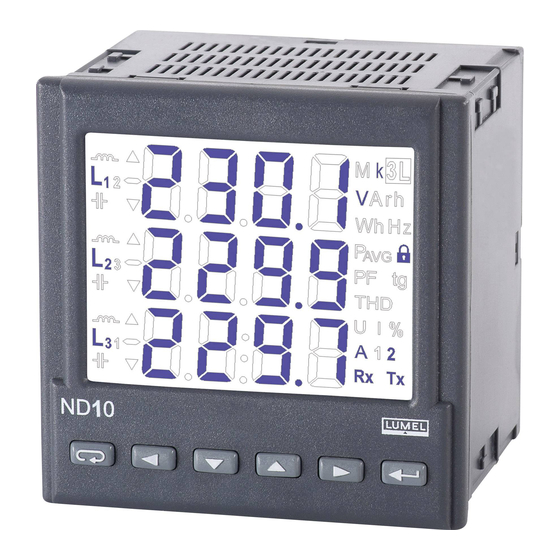
6. ND10 MeTeR PROgRAMMINg 6.1 Front panel Fig. 4. Front panel. front panel description: 8 – connection / alarm symbols 1 – cancel button (eSC) 9 – unit at displaying THD and power 2 – move left button guard 3 – decrease value button 10 –... -
Page 13: Power-On Messages
6.2 Power-on messages After connection of voltage inputs the meter performs a display test and displays the ND10 meter name, build and current software version. where: r n.nn is a number of the current software version or special build number. -
Page 14: Parameter Display
6.3 Parameter display In the measurement mode, values are displayed according to set tables. Pressing button allows user to switch between displayed base values (Table 1). Pressing button displays minimal value and pressing button displays maximal value. When these values are displayed, pressing the button resets all minimal or maximal values. - Page 15 Table 1 , Var , VA , Pf , tg Displayed symbols row 1 Imported active row 2 energy row 3 Display fixed optional fixed optional ,THD u , THD I Displayed -, kWh kVarh kVarh symbols row 1 THD u1 % THD I1 % reactive inductive reactive capacitive...
- Page 16 Table 2 Displayed 3L, V 3L, V 3L, A 3L, W 3L, Var 3L, VA 3L, Pf 3L, tg symbols u LNav. u LLav. I av. 3-phase 3-phase 3-phase When upper limit of the indication range is exceeded, it is in- dicated by two horizontal lines in upper part of the display.
-
Page 17: Operating Modes
6.4 Operating modes Fig. 6. ND10 meter operating modes. -
Page 18: Parameter Settings
6.5 Parameter setting ND10 meters are configured with the use of LPCon software available for free on the www.lumel.com.pl web site. Fig 7. Setup menu. Programming mode is enabled by pressing and holding button for about 3 seconds. To enable the programming user bust enter a correct access code. -
Page 19: Setting Of Meter Parameters
6.5.1 Setting of Meter Parameters In options menu choose PAr (using buttons) and confirm selection with the button. Table 3 Access off, 0 – no code code entry 1 … 60000 Current transformer tr_I 1 … 10000 ratio Voltage transformer tr_u 0.1 … 4000.0 ratio Mean active power synchro- nization: 15 - 15-minute moving... - Page 20 Method of cAP – inductive and capacity reactive energy en_q cAP, sIgn energy sIgn – positive and negative calculation energy Display off, on, 1..60 – illumination oFF,1…60, panel illumi- diSP time (in seconds) from pres- nation sing the button no – no activity, Energy no, EnP, Enq, EnP –...
-
Page 21: Setting Of Output Parameters
6.5.2 Setting of Output Parameters In Options choose the out mode and confirm your choice by pressing the button. Table 4 Number of Io_n 5000 … Number of impulses 5000 impulses 20000 per kWh MODBuS Ne- 1 … 247 twork Address Transmission tryb 8n2,... -
Page 22: Setting Of Alarm Parameters
6.5.3 Setting alarm parameters In Options choose ALr1 or ALr2 mode and confirm your selection by pressing the button. Table 5 Value on alarm A1_n, table 6 output (code as A2_n in Tab. 6) Alarm type A1_t, fig. 8. n-on n-on, n-off, A2_t on,off, H-on, H-off Lower value of A1of,... - Page 23 Alarm signaliza- A1_S, off, When alarm signaliza- tion latch A2_S, tion latch is enabled and the alarm state ends, alarm symbol is not turned off but begins to flash. Alarm symbol flashes until it is turned off by pressing both buttons (for 3 seconds). This function refers only to the alarm signalization, so the relay connectors will...
- Page 24 L1 phase wire current In [A] * L1 phase active power un x In x cos(0°) [W] * L1 phase reactive un x In x sin(90°) [var] * power L1 phase apparent un x In [VA] * power L1 phase active power factor tgj factor of L1 phase L2 phase voltage...
- Page 25 mean 3-phase voltage un [V] * mean 3-phase current In [A] * 3-phase active power 3 x un x In x cos(0°) (P1+P2+P3) [W] * 3-phase reactive power 3 x un x In x sin(90°) (q1+q2+q3) [var] * 3-phase apparent 3x un x In [VA]* power (S1+S2+S3) Pf_A...
- Page 26 a) n-on b) n-oFF c) On d) OFF Fig. 8. Alarm types (x – alarm no.): a),b) normal c) off d) on.
- Page 27 Peak max power consumption 1,5 MW. Calculations: ND10 meter active rated 3-phase power: P = 3 x k = 3 x 1 x 230 V x 500 x 5A = 1,725 MW g100 %. Ordered-to-rated power ratio = 1 MW / 1.725 ≈ MW 57,97 %...
- Page 28 Alarm operation hysteresis: alarm should be activated at 90 % ordered power (A1on), and deactivated for e.g.: at 1 % lower 89 % (A1of). Optimization of power limit function (delay at alarm activation): 1 MW∗900 s =10 %∗ =60 s alarm activation delay (A1dt).
-
Page 29: Setting Date And Time
Set alarm as following: monitored quantity: A1_n = P_ord; alarm type: A1_t = n-on; A1on = 90,0, AL1of = 89,9; delay time A1dt = 0 or 60 s; A1_s = 0; A1_b = 0. Parameters should be set as following: tr_I = 500; Syn = 15 or c_15, and Pord = 57.9. 6.5.4 Setting Date and Time In Options choose dAtE mode and confirm the selection with button. -
Page 30: Software Upgrades
PC with software eCon was implementation in meter ND10 (with digital output). Free software eCon and update files are accessible on the site www.lumel.com.pl. The connected to the computer converter RS485 is required on uSB to the updat- ing, e.g.: the converter PD10. - Page 31 After starting eCon’s software COM port, baudrate, transmission mode and adress should be set. It can be done in Options. Then, ND10 meter should be selected from Device. Push icon Load to read and save current settings. Open window Lumel Updater (LU) – figure 10b from Updating->Updating of devices...
-
Page 32: Rs-485 Interface
Manufacturer’s settings: address 1, speed 9.6 kbit/s, mode RTu 8N2. ND10 meter register map ND10 meter has data contained in 16-bit and 32-bit registers. Process variables and meter parameters are placed in the address area of registers in a way depended on the variable value type. - Page 33 Table 8 Range of Type of Description addresses value Value set in the 16-bit register. 4000 Integer Register description presented – 4057 (16 bits) in Table 9. Read and write registers. Value is set in the two following 16-bit registers. These registers contain the 6000 float same data as 32-bit registers from...
- Page 34 Table 9 Regi- Ope- ster Range Description fault tions dress 4000 0 … 60000 Protection - password 4001 Reserved Mean ordered power *10 4002 0...1200 [ 1000 nominal signals 4003 1 … 10000 Current transformer ratio 4004 1 … 40000 Voltage transformer ratio *10 Mean active power synchronization: 0 - 15-minute moving window...
- Page 35 quantity on the relay output of 4015 0.1...35 alarm 1 (code as in Table 6) Output type 1: 0 – n-on, 1– n-off, 4016 0..5 2 – on, 3 – off, 4 – H-on, 5 – H-off -1440...0...1440 Lower value of the alarm 1 switch 4017 of the rated input range -1440...0...1440...
- Page 36 Transmission speed: 0->4800, 4032 0...3 1->9600, 2->19200, 3->38400 upgrade change of transmission 4033 parameters 4034 0 … 2359 Hour *100 + minutes 4035 101 … 1231 Month * 100 + day 4036 2009 … 2100 year 2009 Standard parameters save (complete with reseting energy 4037 as well as min, max and mean...
- Page 37 4054 0..65535 Serial number two younger bytes 4055 0..65535 Software version (*100) 4056 0..65535 quantity parameters displayed 0xffff 4057 Reserved Brackets [ ] contain, respectively: resolution or unit. energy is made available in hundreds of watt-hours (var-hours) in double 16-bit register, and for this reason, one must divide them by 10 when calculating values of particular energy from registers, e.g.: Imported active energy = (reg.
- Page 38 Status Register (address 4050, R): Bit 15 – „1” – damage of non-volatile memory Bit 14 – „1” – lack of calibration or invalid calibration Bit 13 – „1” – error of parameter values Bit 12 – „1” – error of energy values Bit 11 –...
- Page 39 Status Register – reactive power characteristics (address 4051, R): Bit 15...12 - reserved Bit 11 – „1” – capacity 3L max, Bit 10 – „1” – capacity 3L min. Bit 9 – „1” – capacity 3L Bit 8 – „1” – capacity L3 max. Bit 7 –...
- Page 40 Table 10 dress Address of 32 of 16 bit Description registers regi- sters 6000/7000 7500 L1 phase voltage 6002/7002 7501 L1 phase current 6004/7004 7502 L1 phase active power 6006/7006 7503 L1 phase reactive power 6008/7008 7504 L1 phase apparent power 6010/7010 7505 L1 phase power factor (Pf)
- Page 41 6050/7050 7525 3-phase apparent power (S1+S2+S3) 6052/7052 7526 Mean power factor (Pf) 6054/7054 7527 Mean reactive to active power ratio 6056/7056 7528 frequency 6058/7058 7529 Phase-to-phase voltage L1-L2 6060/7060 7530 Phase-to-phase voltage L2-L3 6062/7062 7531 Phase-to-phase voltage L3-L1 6064/7064 7532 Mean phase-to-phase voltage Active power, 3-phase, 15, 30, 60 minutes 6066/7066...
- Page 42 Reactive 3-phase inductive energy (no. of 6104/7104 7552 register 7553 overflows, resets to 0 after Mvarh reaching 99999999,9 kVarh). Reactive 3-phase inductive energy (counter 6106/7106 7553 kvarh counting up to 99999.9 kVarh) Reactive 3-phase capacity energy (no. of 6108/7108 7554 register 7555 overflows, resets to 0 after Mvarh reaching 99999999,9 kVarh) Reactive 3-phase capacity energy (counter 6110/7110 7555 kvarh...
- Page 43 6156/7156 7578 Active power L2 min 6158/7158 7579 Active power L2 max 6160/7160 7580 Active power L3 min 6162/7162 7581 Active power L3 max 6164/7164 7582 Reactive power L1 min 6166/7166 7583 Reactive power L1 max 6168/7168 7584 Reactive power L2 min 6170/7170 7585 Reactive power L2 max...
- Page 44 6222/7222 7611 Phase-to-phase voltage L3-1 max 6224/7224 7612 Mean 3-phase voltage (min) 6226/7226 7613 Mean 3-phase voltage (max) 6228/7228 7614 Mean 3-phase current (min) 6230/7230 7615 Mean 3-phase current (max) 6232/7232 7616 3-phase active power (min) 6234/7234 7617 3-phase active power (max) 6236/7236 7618 3-phase reactive power (min)
- Page 45 6288/7288 7644 Cos of u1 and I1 angle (min.) 6290/7290 7645 Cos of u1 and I1 angle (max.) 6292/7292 7646 Cos of u2 and I2 angle (min.) 6294/7294 7647 Cos of u2 and I2 angle (max.) 6296/7296 7648 Cos of u3 and I3 angle (min.) 6298/7298 7649 Cos of u3 and I3 angle (max.)
-
Page 46: Error Codes
9. eRROR CODeS During the meter operation, error messages may be displayed. following list shows causes of particular errors. - Err1 – too low voltage or current during measurement: - Pf , tgj , cos, THD less than 10% un, - Pf , tgj , cos... - Page 47 - Err L3 L2 – phase sequence error. Switch phase 2 and phase 3 connections. Message may be disabled by pressing the button. Then the message will be inactive until the meter is turned off and on again; – lower limit exceeded. Measured value is lower that - - - - the lower measuring limit for a given quantity.
-
Page 48: Technical Data
10. TeCHNICAL DATA Measuring Ranges and Admissible Basic Errors Table 11 Measured Indication Measuring Basic value range* range error Current In 0,00 ... 1.5 kA 0,005 ... 1,200 A~ ±0.2% rng 0,00 ... 60 kA 0,025 ... 6.000 A~ Voltage L-N 57.7 V 0,0 ... - Page 49 Power consumption: - in L1 and L2 voltage circuit 0.05 VA - in L3 voltage circuit 3 VA - in current circuits 0.05 VA Display dedicated 3.5” LCD display, Relay outputs 2 relays, volt-free NO contacts current capacity 250 V~/ 0,5 A~ (a.c.) Serial interface /optional/ RS485: address 1..247 mode: 8N2, 8e1, 8O1,8N1...
- Page 50 Reference and rated operating conditions - supply voltage /in L3 phase measurement circuit/: 50 .. 64 V a.c. or 195 .. 253 V a.c. or 246 .. 300 V a.c. 47 ...63 Hz - input signal: 0...0.005...1,2I n for current; 0.85..1,1u n for voltage;...
- Page 51 ND10 meter complies with following standards: Electromagnetic compatibility: - interference immunity acc. to eN 61000-6-2 - interference emission acc. to eN 61000-6-4 Safety requirements: acc. to eN 61010-1 • circuit-to-circuit insulation: basic, • installation category III, • pollution level •...
-
Page 52: Ordering Codes
* after agreeing with the manufacturer Example of Order: The code: ND10 - 2 2 1 00 E 0 means: ND10 – meter of network parameters of ND10 type 2 – current input In: 5 A (X/5), 2 –... -
Page 53: Maintenance And Guarantee
12. MAINTeNANCe AND guARANTee The P43 transducer does not require any periodical maintenance. In case of some incorrect operations: After the dispatch date and in the period stated in the guarantee card: One should return the instrument to the Manufacturer’s quality Inspection Dept. - Page 56 LUMEL S.A. ul. Sulechowska 1, 65-022 Zielona Góra, POLAND tel.: +48 68 45 75 100, fax +48 68 45 75 508 www.lumel.com.pl Export department: tel.: (+48 68) 45 75 139, 45 75 233, 45 75 321, 45 75 386 fax.: (+48 68) 32 54 091...
Need help?
Do you have a question about the ND10 and is the answer not in the manual?
Questions and answers