Table of Contents
Advertisement
Quick Links
Advertisement
Table of Contents

Related Manuals for FIBARO FIBEFGWCEU-201-B


Summary of Contents for FIBARO FIBEFGWCEU-201-B
- Page 1 O P E R A T I N G M A N U A L FIBARO WALLI CONTROLLER FGWCEU-201 v1.1...
-
Page 3: Table Of Contents
Table of contents 1: Important safety information 2: Description and features 2.1: Description 2.2: Main features 3: Specifications 4: First installation 4.1: Installing on a smooth surface with battery supply 4.2: Installing on a mounting box with battery supply 4.3: Installing on a mounting box with an external power supply 8 5: Adding to Z-Wave network 5.1: Adding manually 5.2: Adding using SmartStart... -
Page 4: 1: Important Safety Information
1: Important safety information Read this manual before attempting to install the device! Failure to observe recommendations included in this manual may be dangerous or cause a violation of the law. The manu- facturer, Fibar Group S.A. will not be held responsible for any loss or damage resulting from not following the instructions of operating manual. -
Page 5: 2: Description And Features
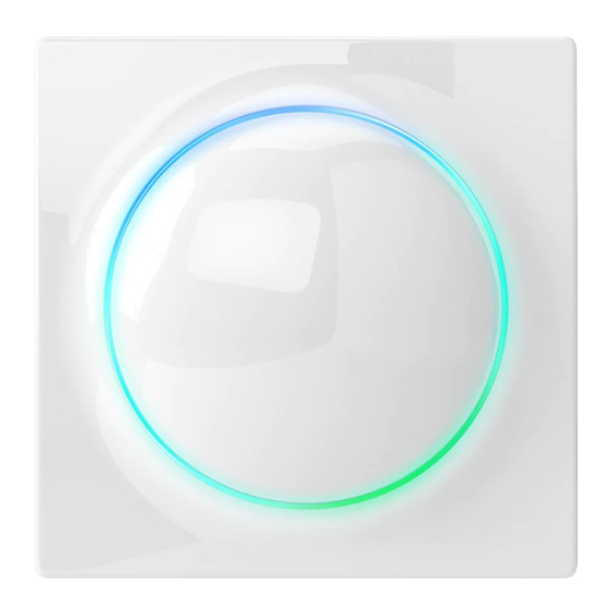
2: Description and features 2.1: Description FIBARO Walli Controller is a smart wall-mounted Z-Wave™ remote controller that can activate scenes or control other Z-Wave devices via associations. 2.2: Main features • Can be used for controlling multiple types of devices, e.g. switch- es, dimmers, roller shutters. -
Page 6: 3: Specifications
3: Specifications Power supply Battery and/or power supply unit Battery type ER14250 ½AA 3.6V (included) Supply unit type 5–24V DC SELV power supply, LPS or NEC class 2 (not included) Battery life est. 2 years (with default settings and max. 10 pushes per day) Operating temperature 0–40°C Ambient humidity... -
Page 7: 4: First Installation
4: First installation You can install the device on any smooth surface using included ad- hesive tape or on a mounting box using screws. The device will select the powering mode during adding to the Z-Wave network, prioritizing external power supply if connected. -
Page 8: Installing On A Mounting Box With An External Power Supply
* To ensure no contact with electrical wires in the box, mount the frame so that the power port is obscured by it. 4.3: Installing on a mounting box with an external power supply Prepare the power supply 1. Switch off the mains voltage (disable the fuse). 2. -
Page 9: 5: Adding To Z-Wave Network
5: Adding to Z-Wave network Adding (Inclusion) – Z-Wave device learning mode, allowing to add the device to existing Z-Wave network. The device will select the powering mode during adding to the Z-Wave network, prioritizing external power supply if connected. To change the mode after adding, you must re- move it, change the installation accordingly, then add the device again. -
Page 10: Adding Using Smartstart
5.2: Adding using SmartStart SmartStart enabled products can be added into a Z-Wave network by scanning the Z-Wave QR Code present on the product with a con- troller providing SmartStart inclusion. SmartStart product will be added automatically within 10 minutes of being switched on in the network range. -
Page 11: 6: Removing From Z-Wave Network
6: Removing from Z-Wave network Removing (Exclusion) – Z-Wave device learning mode, allowing to remove the device from existing Z-Wave network. Removing also re- sults in resetting the device to factory defaults. To remove the device from the Z-Wave network: 1. Set the main controller into remove mode (see the controller’s manual). -
Page 12: 7: Operation
7: Operation 7.1: Controls 1. First/ button, 2. Second/ button, 3. LED ring. 7.2: Operating modes Scene Controller This mode is enabled by default or by setting parameter 20 to 0. In this mode, the device can activate scenes in the Z-Wave controller by sending scene ID and attribute of a specific action (using Central Scene Command Class). - Page 13 1st button – controls 2nd and 3rd group: • Click – alternately ON with last level / OFF, • 2xClick – send pre-set level (set in parameter 152), • Hold – alternately increasing/decreasing level until released. 2nd button – controls 4th and 5th group: •...
-
Page 14: Powering Modes
Roller Shutter Step-By-Step Controller This mode is enabled by setting parameter 20 to 5. In this mode the device uses associations to control Z-Wave roller shutter controllers (group 6) in Step-By-Step mode (alternately sends commands for movement and stopping). 1st button – opens and stops: •... -
Page 15: Temperature Sensor
Battery mode In battery mode, the device indicates commands status, but cannot receive indications from the Z-Wave controller (using Indicator CC), except for Identification. The device needs to be woken up to change its configuration. The battery level (in percent) is measured during every power up and periodically every 24h, the measured value is reported to the con- troller during every power up and when it changes by at least 5%. -
Page 16: Menu
Command status: The device displays last command status in response to clicking/ holding a button. • Green for 2 seconds – command acknowledged, • Red for 2 seconds – command not acknowledged. Identification: The Z-Wave controller can identify this device by signalling with LED ring (using Indicator CC). -
Page 17: Resetting To Factory Defaults
5. Quickly click the button to confirm. 7.8: Resetting to factory defaults Reset procedure allows to restore the device back to its factory set- tings, which means all information about the Z-Wave controller and user configuration will be deleted. Resetting the device is not the recommended way of re- moving the device from the Z-Wave network. -
Page 18: 8: Configuration
8: Configuration 8.1: Associations Association (linking devices) – direct control of other devices with- in the Z-Wave system network. Associations allow: • reporting the device status to the Z-Wave controller (using Lifeline group), • creating simple automations by controlling other devices without participation of the main controller (using groups assigned to ac- tions on the device). - Page 19 Commands sent to association groups in Double Button Mode (parameter 20 set to 1) 1 click 2 click Hold Release Multilevel Multilevel Button Basic Set: Basic Set: Start Change: Stop Change: 2nd group 2nd group 3rd group 3rd group Multilevel Multilevel Button Basic Set: 4th...
- Page 20 1 click 2 click Hold Release Multilevel Multilevel Button Start / Stop Set: 6th – – 1 (up) Change: 6th group group Multilevel But- Multilevel Start / Stop ton 2 Stop Change: – – Change: 6th (down) 6th group group Commands sent to association groups in Venetian Blinds Step- By-Step Controller Mode (parameter 20 set to 6) 1 click...
-
Page 21: Advanced Parameters
The settings can be adjusted via Z-Wave controller to which the de- vice is added. The way of adjusting them might differ depending on the controller. In the FIBARO interface parameters are presented as simple options in Advanced Settings of the device. Available parameters: LED frame –... - Page 22 150. LED ring – first button This parameter defines the colour of first button Description indicator (upper part of the LED ring) for indica- tions using Indicator CC. Parameter size 2B Default value 1 (white) 0 – LED disabled 1 – White 2 –...
- Page 23 152. 1st button - double click value This parameter defines value of Basic Set or Multilevel Set frame (depending on selected Description mode) sent to associated devices after double click. This parameter is not relevant for Scene Controller Mode. Parameter size 2B Default value Available 0-99 or 255...
-
Page 24: 9: Z-Wave Specification
9: Z-Wave specification Generic Device Class: GENERIC_TYPE_WALL_CONTROLLER Specific Device Class: not used Supported Command Classes Command Class Version Secure 1.COMMAND_CLASS_ZWAVEPLUS_INFO [0x5E] 2.COMMAND_CLASS_ASSOCIATION [0x85] COMMAND_CLASS_MULTI_CHANNEL_ASSOCI- ATION [0x8E] COMMAND_CLASS_ASSOCIATION_GRP_INFO [0x59] 5.COMMAND_CLASS_INDICATOR [0x87] COMMAND_CLASS_TRANSPORT_SERVICE [0x55] 7.COMMAND_CLASS_VERSION [0x86] COMMAND_CLASS_MANUFACTURER_SPECIFIC [0x72] COMMAND_CLASS_DEVICE_RESET_LOCALLY [0x5A] 10.COMMAND_CLASS_POWERLEVEL [0x73] 11.COMMAND_CLASS_SECURITY [0x98] 12.COMMAND_CLASS_SECURITY_2 [0x9F] 13.COMMAND_CLASS_SUPERVISION [0x6C] 14.COMMAND_CLASS_CONFIGURATION [0x70]... - Page 25 Wake Up CC (only in battery mode) Min. Interval Seconds 0 – off, 3600 [s] = 1 [h] Max. Interval Seconds 43200 [s] = 12[h] Default Interval Seconds 21600 [s] = 6 [h] Interval Step Seconds 3600 Default NodeID Additional Sending Frame Menu –...
- Page 26 Used to set the number of On/Off periods. Available values: • 0x00 .. 0xFE (0 .. 254 times) 0x04 On/Off Cycles • 0xFF (indicate until stopped) If this is specified, the On/Off Period MUST also be specified. Used to set the length of the On time dur- ing an On/Off period.
-
Page 27: 10: Regulations
FIBARO and Fibar Group logo are trademarks of Fibar Group S.A. All other brands and product names referred to herein are trademarks of their respective holders.
Need help?
Do you have a question about the FIBEFGWCEU-201-B and is the answer not in the manual?
Questions and answers