Table of Contents
Advertisement
Quick Links
Advertisement
Table of Contents

Related Manuals for IFM ANT515


Summary of Contents for IFM ANT515
- Page 1 Operating instructions RF-identification system ANT515 ANT516 Read/write head...
-
Page 2: Table Of Contents
ANT515 ANT516 Contents Preliminary note ............. -
Page 3: Preliminary Note
Warning of damage to property 1.3 Legal and copyright information © All rights reserved by ifm electronic gmbh. No part of these instructions may be reproduced and used without the consent of ifm electronic gmbh. All product names, pictures, companies or other brands used on our pages are the property of the... -
Page 4: Safety Instructions
ANT515 ANT516 2 Safety instructions General • The unit described is a subcomponent for integration into a system. – The system architect is responsible for the safety of the system. – The system architect undertakes to perform a risk assessment and to create documentation in accordance with legal and normative requirements to be provided to the operator and user of the system. -
Page 5: Intended Use
ANT515 ANT516 3 Intended use The read/write head reads and writes ID tags without contact. For use, the read/write head must be connected to the DTE10x evaluation unit. The data is converted into digitally coded values and provided to the evaluation unit. -
Page 6: Function
ID tag. A voltage is generated by induction that supplies the data carrier with energy. The device supports ID tags according to ISO 15693. 4.2 Device overview Article number: ANT515 / ANT516 Function: read/write head Type designation: DTRHF KQRWIDUS03... -
Page 7: Installation
ANT515 ANT516 5 Installation 5.1 Notes on the unit installation When mounting several RFID units adhere to the minimum distances between the systems. Flush mounting of a read/write head in metal reduces the read/write distance. Device performance can be affected if positioned in the immediate vicinity of powerful HF emission sources such as welding transformers or converters. - Page 8 ANT515 ANT516 Fig. 1: Insert the device in the mounting adapter 1 Upper edge of the device 2 Lower edge of the device u Insert the upper edge of the device (1) into the mounting adapter. u Insert the lower edge of the device (2) into the mounting adapter.
-
Page 9: Installation Of The Device With Mounting Adapter On The Pipe
ANT515 ANT516 Fig. 3: Attach the mounting adapter to the tank 4 Screws u Attach the mounting adapter to a tank with suitable screws (4). 5.5 Installation of the device with mounting adapter on the pipe The mounting adapter for pipes is available as accessory: article number E12163. -
Page 10: Installation Of The Device Without Mounting Adapter
ANT515 ANT516 5.6 Installation of the device without mounting adapter Fig. 5: Install the device using screws u Attach the device at the mounting location with suitable screws or glue. 5.7 Mounting distances Operating mode Distance side (A) Distance front (B) For reading and writing ≥... - Page 11 ANT515 ANT516 Fig. 6: Position the ID tag u Align the ID tag on the central axis of the antenna of the device. w The distance “D” is indicated in the data sheet. The indications in the table apply to static read/write operations.
-
Page 12: Electrical Connection
Connect the unit to a DTE10x evaluation unit via the M12 connector. w Voltage is supplied via the evaluation unit. Pin assignment Wiring DATA Information on available sockets see: www.ifm.com. Cables with the following characteristics are suitable for the connection: Length Ohmic resistance (feed + return line) Effective cable capacity <... -
Page 13: Operating And Display Elements
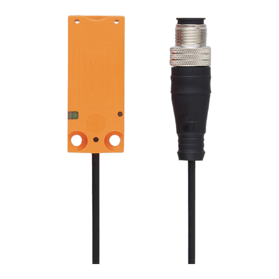
ANT515 ANT516 7 Operating and display elements Fig. 7: Operating and display elements 1 LED 2 Sensing face State Description green Operating voltage OK Operating voltage missing Flashing slowly deactivated yellow On (permanently) ID tag detected On (pulse) ID tag read/written successfully... -
Page 14: Maintenance, Repair And Disposal
8 Maintenance, repair and disposal The unit is maintenance-free. u Contact ifm in case of malfunction. u Do not open the housing as the unit does not contain any components which can be maintained by the user. The unit must only be repaired by the manufacturer. -
Page 15: Approvals/Standards
ANT515 ANT516 9 Approvals/standards For approvals and standards, the following information is available: • Test standards and regulations: documentation.ifm.com • EU declaration of conformity and approvals: documentation.ifm.com • Notes relevant for approval: package inserts of the device... -
Page 16: Glossary
ANT515 ANT516 Glossary ID tag An ID tag is used to identify objects. A read/ write device is used to read the ID tag via a high-frequency radio signal. An ID tag consists of an antenna, an analogue circuit for receiving and transmitting (transceiver),...
Need help?
Do you have a question about the ANT515 and is the answer not in the manual?
Questions and answers