Table of Contents
Advertisement
Advertisement
Table of Contents

Related Manuals for Renishaw TS27R


Summary of Contents for Renishaw TS27R
- Page 1 Installation and user’s guide H-2000-5018-10-A TS27R – tool setting probe...
- Page 2 Publications for this product are available by scanning the barcode or visiting www.renishaw.com/ts27r. Für dieses Produkt stehen weitere Informationen zur Verfügung. Scannen Sie dazu den Barcode oder besuchen Sie www.renishaw.de/ts27r. Para acceder a las publicaciones sobre este producto escanee el código de barras o visite www.renishaw.es/ts27r.
- Page 3 Le pubblicazioni relative a questo prodotto sono disponibili scansionando il codice a lato oppure visitando il sito: www.renishaw.it/ts27r. 日本語 本製品に関する資料については、 バーコードをスキャンするか www.renishaw.jp/ts27r をご覧ください。 Если вас интересует информация об этом продукте, отсканируйте штрих-код или посетите сайт www.renishaw.ru/ts27r. 中文 可通过以下方式获得此产品的相关文档: 扫描二维码,或访问 (简体) www.renishaw.com.cn/ts27r。...
- Page 4 © 1995–2020 Renishaw plc. All rights reserved. This document may not be copied or reproduced in whole or in part, or transferred to any other media or language, by any means, without the prior written permission of Renishaw. The publication of material within this document does not imply freedom from the patent rights of Renishaw plc.
-
Page 5: Table Of Contents
Contents Safety ..............2 Recommended connection diagram for TS27R with MI 8-4 interface ......14 Safety ............2 TS27R probe system .........4 Fitting the stylus and captive link ....16 Introduction ...........5 Break stem ............17 Operation ............6 Stylus level setting ..........18 Achievable set-up tolerances ......6 Recommended rotating tool feedrates ..6... -
Page 6: Safety
Refer to the machine supplier’s operating to function in accordance with these regulations: instructions. The TS27R system must be installed by a • any interface MUST be installed in a position competent person, observing relevant safety away from any potential sources of electrical precautions. - Page 7 Safety Equipment operation If this equipment is used in a manner not specified by the manufacturer, the protection provided by the equipment may be impaired.
-
Page 8: Ts27R Probe System
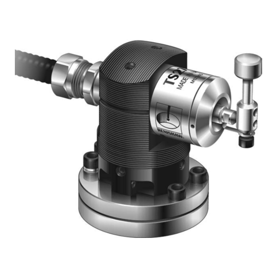
TS27R probe system Diameter setting Alternative interface units Rotate tool in TS27R probe reverse direction Cable MI 8-4 interface machine controller HSI interface Machine table T slot HSI-C interface 1. Stylus 7. Stylus level alignment – adjusting screws 2. Stylus holder for disc or square styli 8. -
Page 9: Introduction
TS27R probe system Introduction The TS27R probe is used for tool setting on CNC machining centres. For tool length measurements and broken tool detection, the tool is driven against the probe’s stylus in the Z axis. Rotating tools can be set in the X and Y axes for tool radius offsets. -
Page 10: Operation
Cutters should be rotated in reverse to the cutting Software routines for tool setting are available direction. from Renishaw for various machine controllers and are described in the Probe software for machine tools – programs and features data sheet First touch – machine spindle rev/min (Renishaw part no. -
Page 11: Specification
Specification Principal application Tool measuring and broken tool detection on all sizes of vertical and horizontal machining centres and all gantry machining centres. Transmission type Hard-wired transmission Receiver/interface MI 8-4, HSI or HSI-C Recommended styli Disc stylus (tungsten carbide, 75 Rockwell C) or Square tip stylus (ceramic tip, 75 Rockwell C) Weight with disc stylus 1055 g (37.21 oz) - Page 12 Trigger force is measured with a 50 mm (1.97 in) stylus. Note 3 These are the factory settings; manual adjustment is not possible. NOTE: For stylus recommendations, refer to the Styli and accessories technical specification (Renishaw part no. H-1000-3200).
-
Page 13: Dimensions
Dimensions overtravel overtravel 5.5 (0.21) at Minimum 10° stylus centre in all axes 47 (1.85) 56 (2.20) 27 (1.06) 8 (0.31) X/Y X/Y Stylus Stylus pivot point Conduit adaptor Machine table Ø54 (Ø2.125) PCD T bolt assembly Ø62.5 (Ø2.46) to be supplied by user. Two holes Bolt diameter M12 (0.50) maximum for Spirol... -
Page 14: Installation
However two Spirol ® pins (supplied in the probe kit) may be fitted on installations where there is a requirement to remove and remount the TS27R. To fit the Spirol pins, drill two holes in the machine table ®... -
Page 15: Interfaces
Renishaw recommends that Thomas and Betts tool setting probe and an inspection probe. Type EF conduit, or a suitable alternative, is fitted to all installations. The TS27R conduit adaptor The HSI and HSI-C interfaces are used with the accepts Ø11 mm (0.43 in) flexible conduit. -
Page 16: Recommended Connection Diagram For Ts27R With Hsi-C Interface
Recommended connection diagram for TS27R with HSI-C interface HSI-C interface Machine tool NOTE: When Probe connector (5-way) TS27R tool connecting the TS27R setter probe to the HSI-C Blue Block 4 TS27R 17. Screen interface, please use probe 16. Standard probe input + the connection labelled 15. -
Page 17: Recommended Connection Diagram For Ts27R With Hsi Interface
Recommended connection diagram for TS27R with HSI interface HSI interface Machine tool NOTE: When Standard connector (3-way) connecting the TS27R TS27R tool setter probe to the HSI Blue 1 Probe Input + interface, please use TS27R probe the connection labelled 2 Probe Input −... -
Page 18: Recommended Connection Diagram For Ts27R With Mi 8-4 Interface
Recommended connection diagram for TS27R with MI 8-4 interface MI 8-4 interface CNC controller +Vdc from I/O supply A10 isolated output + supply SKIP input (G31) A11 probe status output (totem pole) −Vdc from I/O supply A12 isolated output − supply Screen B4 SELX−... - Page 19 Recommended connection diagram for TS27R with MI 8-4 interface Machine tool Screen TS27R tool setter Blue Probe + Probe input TS27R probe Probe − For information regarding these connections, see the MI 8-4 interface unit 100 nF installation and user’s capacitor* guide (Renishaw part no.
-
Page 20: Fitting The Stylus And Captive Link
Fitting the stylus and captive link Spanner 5 mm A/F TS27R 2.5 Nm – 2.7 Nm Stylus (1.84 lbf.ft – 1.99 lbf.ft) Stylus Break stem holder Captive link 2 mm A/F 1.0 Nm – 1.2 Nm (0.74 lbf.ft – 0.89 lbf.ft) -
Page 21: Break Stem
2.5 Nm – 2.7 Nm (1.84 lbf.ft – 1.99 lbf.ft) Stylus and holder NOTE: Earlier versions of the TS27R were Place the stylus and holder onto the break stem supplied with cup-pointed grubscrews and a and loosely fit grubscrew B. -
Page 22: Stylus Level Setting
Stylus level setting L3 and L4 CAUTION: Do not stress the break stem 2.5 mm A/F Square stylus Disc stylus 0.7 Nm – 0.9 Nm (0.52 lbf.ft – 0.66 lbf.ft) Side Back Side Front H, L1 and L2 Screw with 4 mm A/F spring washer 4.6 Nm –... -
Page 23: Square Stylus Alignment
Square stylus alignment CAUTION: Always hold the support bar 2 mm A/F in position to counteract twisting forces 1.0 Nm – 1.2 Nm L3 and L4 and avoid over-stressing the stylus (0.74 lbf.ft – 0.89 lbf.ft) level break stem. coarse rotational side to side adjustment 2.5 mm A/F... -
Page 24: Service And Maintenance
Ensure the probe is firmly secured to its mounting. equipment is a highly specialised operation, which must be carried out at authorised Renishaw The probe requires minimal maintenance as it is service centres. designed to operate as a permanent fixture on... -
Page 25: Diaphragm Maintenance
Diaphragm maintenance C spanner 3.6 Nm – 4.4 Nm (2.66 lbf.ft – 3.25 lbf.ft) Spanner 5 mm A/F 2.5 Nm – 2.7 Nm (1.84 lbf.ft – 1.99 lbf.ft) Break stem Front cover with O-ring Captive link 1. Remove the stylus and holder (see page 17). 4. -
Page 26: Parts List
HSI stylus 19.05 mm (0.75 in) and HSI interface. TS27R (disc) A-2008-0368 TS27R holder, probe module, break stem (× 2) and disc stylus Ø12.7 mm (Ø0.5 in). TS27R A-2008-0388 TS27R holder, probe module, break stem (× 2) and stylus holder (without stylus). - Page 27 Parts list Type Part Number Description Square stylus A-2008-0384 Square tip stylus 19.05 mm (0.75 in), ceramic tip, 75 Rockwell C. Grubscrew P-SC11-0404 Grubscrew (flat end) for stylus holder M4 × 4 mm (two required). Screw P-SC01-X406 M4 cap head screw for stylus holder (one required). C spanner A-2008-0332 C spanner –...
- Page 28 Parts list Type Part Number Description Publications. These can be downloaded from our website at www.renishaw.com. TS27R H-2000-5018 Installation and user’s guide: TS27R tool setting probe. MI 8-4 H-2000-5008 Installation and user’s guide: MI 8-4 interface unit. HSI QSG H-5500-8550 Quick-start guide: for rapid set-up of the HSI interface.
-
Page 29: General Information
Trade marks exclusions from the warranty are if the equipment has been: RENISHAW and the probe symbol used in the RENISHAW logo are registered trade marks of • neglected, mishandled or inappropriately Renishaw plc in the United Kingdom and other used;... -
Page 30: Changes To Equipment
Renishaw reserves the right to change equipment specifications without notice. Renishaw plc declares under its sole responsibility CNC machines that the TS27R is in conformity with all relevant Union legislation. CNC machine tools must always be operated by fully trained personnel in accordance with the The full text of the EU declaration of conformity is manufacturer’s instructions. -
Page 31: Weee Directive
(EC) No. 1907/2006 (“REACH”) relating to products containing substances of very high concern (SVHCs) is available at: www.renishaw.com/REACH The use of this symbol on Renishaw products FCC Information to user (USA only) and/or accompanying documentation indicates that the product should not be mixed with 47 CFR Section 15.19... - Page 32 General information 47 CFR Section 15.105 This equipment has been tested and found to comply with the limits for a Class A digital device, pursuant to part 15 of the FCC Rules. These limits are designed to provide reasonable protection against harmful interference when the equipment is operated in a commercial environment.
- Page 33 General information 雷尼绍(上海)贸易有限公司 如果测头测量失败,则有误发测头已复位状态信号 的可能。切勿单凭测头信号来停止机床运动。 中国上海市静安区江场三路288号 18幢楼1楼 设备安装商须知 200436 雷尼绍所有设备的设计均符合相关的EU和FCC监 T +86 21 6180 6416 管要求I为使产品按照这些规定工作,设备安装商有 F +86 21 6180 6418 责任保证遵守以下指导原则: E shanghai@renishaw.com • 任何接口的安装位置必须远离任何潜在的电噪 www.renishaw.com.cn 声源,如变压器、伺服系统驱动装置等; • 安全须知 所有0伏/接地连接都应当连接到机床接地终端 上(“接地终端”是所有设备地线和屏蔽电缆 用户须知 的单点回路)。这一点非常重要,不遵守此规 定会造成接地之间存在电位差; 在所有涉及使用机床或坐标测量机 (CMM) 的应用 中,建议采取保护眼睛的措施。 •...
- Page 36 Renishaw plc +44 (0)1453 524524 +44 (0)1453 524901 New Mills, Wotton-under-Edge uk@renishaw.com Gloucestershire, GL12 8JR United Kingdom www.renishaw.com For worldwide contact details, visit www.renishaw.com/contact *H-2000-5018-10*...
Need help?
Do you have a question about the TS27R and is the answer not in the manual?
Questions and answers