Table of Contents
Advertisement
Quick Links
O
P
E
R
A
O
P
E
R
A
TH2829X Series
C C
h h
a a
n n
g g
z z
h h
o o
u u
T T
C
h
a
n
g
z
h
o
u
T
A A
d d
d d
: : No.3, Tianshan Road, New District, Changzhou, Jiangsu
A
d
d
:
T T
e e
l l
: :
( (
T
e
l
:
(
F F
a a
x x
: :
F
a
x
:
( (
(
E E
- -
m m
a a
E
-
m
W W
e e
b b
s s
i i
t t
e e
W
e
b
s
i
t
e
T
I
O
N
M
A
T
I
O
N
M
A
o o
n n
g g
h h
u u
i i
E E
l l
e e
c c
t t
r r
o
n
g
h
u
i
E
l
e
c
t
r
0 0
5 5
1 1
9 9
8 8
5 5
1 1
9 9
5 5
5 5
6 6
6 6
8 8
) )
, ,
0
5
1
9
8
5
1
9
5
5
6
6
8
)
,
0 0
5 5
1 1
9 9
8 8
5 5
1 1
0 0
9 9
9 9
7 7
2 2
0
5
1
9
) )
8
5
1
0
9
9
7
2
)
i i
l l
: :
S S
a a
l l
e e
s s
@ @
t t
o o
n n
g g
h h
u u
i i
. .
c c
o o
a
i
l
:
S
a
l
e
s
@
t
o
n
g
h
u
i
.
c
: :
h h
t t
t t
p p
: :
/ /
/ /
w w
w w
w w
. .
t t
o o
n n
g g
h h
u u
:
h
t
t
p
:
/
/
w
w
w
.
t
o
n
g
h
N
U
A
L
N
U
A
L
o o
n n
i i
c c
C C
o o
. .
, ,
L L
t t
d d
o
n
i
c
C
o
.
,
L
t
d
5 5
1 1
3 3
2 2
2 2
2 2
2 2
5
1
3
2
2
2
2
m m
. .
c c
n n
o
m
.
c
n
i i
. .
c c
o o
m m
. .
c c
n n
u
i
.
c
o
m
.
c
n
. .
.
Advertisement
Table of Contents

Related Manuals for Tonghui TH2829 Series


Summary of Contents for Tonghui TH2829 Series
- Page 1 TH2829X Series : : No.3, Tianshan Road, New District, Changzhou, Jiangsu ( ( ) ) , , ( ) , ( ( ) ) ( )...
-
Page 2: Table Of Contents
TH2829X Series Operation Manual Contents Contents Chapter 1 Out of Box Audit ..............1 To Inspect the package ............1 Power connection ..............1 Fuse ..................1 Environment ................. 2 Use of Test Fixture ..............2 Warm-up ................2 Other features ............... 3 Chapter 2 Introduction ................ - Page 3 TH2829X Series Operation Manual Contents 3.4.4 CMP (Compare)...............24 <TRACE SWEEP> ..............24 3.5.1 FORMAT .................25 3.5.2 SCALE ................25 3.5.3 READ ................25 3.5.4 TRACE ................26 3.5.5 POINTS ................26 3.5.6 TRIGGER ................26 3.5.7 SAVE CSV & SAVE AS ............26 <MEAS SETUP> ..............27 3.6.1 Trigger mode ..............29 3.6.2 Auto level control function ..........29...
- Page 4 TH2829X Series Operation Manual Contents 3.10.9 Format ................48 3.10.10 Trigger ................48 3.10.11 Mode ................48 3.10.12 Start delay ..............49 3.10.13 Point ................49 3.10.14 Step delay ..............49 3.10.15 Maximum and minimum ...........49 3.10.16 START ................49 3.10.17 END ................49 3.10.18 Coordination range settiing ..........49 Chapter 4 [SYSTEM] and <FILE MANAGE>...
- Page 5 TH2829X Series Operation Manual Contents 6.1.4 Capacitance test between windings of transformer ....72 <Transformer Measure Setup> ..........73 6.2.1 DELAY ................74 6.2.2 Bias................74 6.2.3 MODE ................74 6.2.4 Setting TURN test conditions ..........75 6.2.5 Setting Lx test conditions ..........75 6.2.6 Setting DCR test conditions ..........76 6.2.7 Test frequency, voltage and switch ........76 <TRANS LIMIT SETUP>...
- Page 6 TH2829X Series Operation Manual Contents 7.7.20 PRIMARY NUMS ...............97 7.7.21 SECONDARY NUMS ............97 7.7.22 RESCAN INTERVAL ............97 7.7.23 SCAN DISP MODE............98 7.7.24 FAIL RESCAN ..............98 7.7.25 DCR MEAS DELAY ............98 7.7.26 DCR OVER DELAY ............98 7.7.27 IBIAS ON DELAY .............99 7.7.28 IGNORE NOM ..............99 7.7.29 TRIGGER DELAY ..............99 7.7.30 CYLINDER CTRL ..............99...
- Page 7 TH2829X Series Operation Manual Contents 7.16 Frequently asked questions and answers in transformer scan test 7.16.1 High and low limits ............135 7.16.2 Measurement item loss ..........135 7.16.3 Measurement interruption ..........136 7.16.4 Poor DCR accuracy ............136 7.16.5 Poor Lk accuracy ............136 7.16.6 Inaccurate TURN ............
- Page 8 TH2829X Series Operation Manual Contents 8.3.2 D accuracy ..............147 8.3.3 Q accuracy ..............147 8.3.4 Θ accuracy ..............147 8.3.5 G accuracy ..............147 8.3.6 Rp accuracy ..............148 8.3.7 Rs accuracy ..............148 8.3.8 Accuracy factor ............. 148 8.3.9 DCR accuracy ...............
- Page 9 TH2829X Series Operation Manual Contents 9.1.17 TRAN subsystem commands ........... 187 GPIB Common Commands ........... 196 Chapter 10 Description for Handler ............200 10.1 Technology description ............200 10.2 Operation description .............. 200 Announcement The description of the manual may not cover all contents of the instrument, and our company is subject to change and to improve the performance, function, inner structure, appearance, accessory and package of the instrument without notice.
-
Page 10: Chapter 1 Out Of Box Audit
TH2829X Series Operation Manual Chapter 1 Out of Box Audit Chapter 1 Out of Box Audit When you receive the instrument, some inspections are necessary, and the condition must be understood and available before installing the instrument. 1.1 To Inspect the package Inspect the shipping container for damage after unpacking it. -
Page 11: Environment
TH2829X Series Operation Manual Chapter 1 Out of Box Audit 1.4 Environment 1) Please do not operate the instrument in the place that is vibrative, dusty, under direct sunlight or where there is corrosive air. 2) The normal working temperature is 0℃~40℃, relative humidity ≤75%, so the instrument should be used under above condition to guarantee the accuracy. -
Page 12: Other Features
TH2829X Series Operation Manual Chapter 1 Out of Box Audit 1.7 Other features 1) Power: consumption power≤80VA. 2) Dimension (W*H*D): 430mm*185mm*473mm 3) Weight: About 13kg. -
Page 13: Chapter 2 Introduction
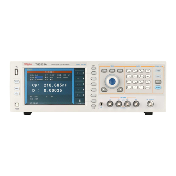
TH2829X Series Operation Manual Chapter 2 Introduction Chapter 2 Introduction In this chapter, the basic operation features of TH2829X series are described. Please read the content carefully before using TH2829X series instruments, thus you can learn the operation of TH2829X. 2.1 Introduction to front panel Figure 2-1 shows the front panel of TH2829X. - Page 14 TH2829X Series Operation Manual Chapter 2 Introduction conditions. 7) [COPY] Copy the currently displayed page to USB memory. 8) [DISP] Press this key to enter into the corresponding test display page. 9) [SETUP] Press this key to enter into the corresponding test setup page. 10) [SYSTEM] Press this key to enter into the system setup page.
-
Page 15: Introduction To Rear Panel
TH2829X Series Operation Manual Chapter 2 Introduction 23) Confirmation key This key is used to end the data input, confirm and save the data input through knob. 24) Ground terminal The ground terminal is connected with the case of instrument, which can be used to protect or shield the ground connection. -
Page 16: Introduction To Display Zone
TH2829X Series Operation Manual Chapter 2 Introduction 6) IEEE-488 interface The tester can communicate with PC through GPIB interface. 7) RS232 interface Series communication interface can realize the communication with PC. 8) Fan window Heat elimination, maintaining the normal working temperature 9) Power socket Input AC power. -
Page 17: Main Menu Keys And Corresponding Displayed
TH2829X Series Operation Manual Chapter 2 Introduction 2) Soft keys The zone is used to display the function definition of soft key. The definition of soft key can be different as the difference of cursor’s direction in the zone. 3) Test result/ condition display zone In this zone, test result information and current condition are displayed. -
Page 18: System]
TH2829X Series Operation Manual Chapter 2 Introduction the following soft keys will be displayed on the transformer measurement setup page. <TRANS MEAS> <LIMIT TABLE> <CORRECTION> <FILE MANAGE> When the transformer scan function is active, press this key-[SETUP], the following soft keys will be displayed on the transformer scan setup page. <TRANS ID>... -
Page 19: Start The Instrument
TH2829X Series Operation Manual Chapter 2 Introduction 2.6 Start the instrument Plug in 3-line power plug. Caution: Keep the power-supply voltage and frequency conform to above specifications. Power input phase line L, zero line N, ground line E should be the same as that of the instrument. -
Page 20: Chapter 3 Introduction To [Disp]
TH2829X Series Operation Manual Chapter 3 Introduction to [MEAS] Chapter 3 Introduction to [DISP] 3.1 <MEAS DISPLAY> When the LCR function is applied, press [DISP], the <MEAS DISPLAY> page will be displayed on screen as shown in the following figure. TH2829X-301 On this page, the test result is displayed in upper-case character. -
Page 21: Test Function
TH2829X Series Operation Manual Chapter 3 Introduction to [MEAS] 3.1.1 Test function In a measurement period, TH2829X can test four parameters for an impedance component: two primary parameters and two secondary parameters. Parameters that can be tested are as follows: Primary parameters |Z| (Module of impedance) ... - Page 22 TH2829X Series Operation Manual Chapter 3 Introduction to [MEAS] Cs-Q Cs-Rs ← Press the soft key corresponding to your desired parameter. Then press ← to return to upper soft key menu. 4) Press Lp—…→, the following parameters will be shown for your choice. Lp-D ...
-
Page 23: Test Range
TH2829X Series Operation Manual Chapter 3 Introduction to [MEAS] Rs-Q ← Press the soft key corresponding to your desired parameter. Then press ← to return to upper soft key menu. Parameter setup of FUNCB is the same as that of FUNCA, but FUNCB can be turned off (OFF). -
Page 24: Test Level
TH2829X Series Operation Manual Chapter 3 Introduction to [MEAS] Operation steps for setting test frequency: TH2829X provides two methods to set measurement frequency. The first one is to use soft keys and the other one is to input data by using numeric keys. 1) Move the cursor to the FREQ zone, the following soft keys will be displayed. -
Page 25: Dc Bias
TH2829X Series Operation Manual Chapter 3 Introduction to [MEAS] the test function is DCR, the LEVEL zone will display “---”. Level voltage and resolution Level voltage Resolution 5mVrms ~ 100mVrms 100 μVrms 100 mVrms ~ 1Vrms 1mVrms 1Vrms ~ 2Vrms 10mVrms ———————————————————————————————————————... -
Page 26: Test Speed
TH2829X Series Operation Manual Chapter 3 Introduction to [MEAS] keys, while the second one is to input data by numeric keys. 1) Move the cursor to DC BIAS, the following soft keys will be displayed. ↑(++) Press this soft key to coarsely increase the output level of DC bias. ↑(+) ... -
Page 27: Save Lcr Test Result By U Disk
TH2829X Series Operation Manual Chapter 3 Introduction to [MEAS] this function can change the displayed digits of test result. This displayed result can be selected to be shown in large character or tiny character. Operation steps for tools Set the display mode of decimal point in fixed mode according to the following operation steps. -
Page 28: Bin No. Disp
TH2829X Series Operation Manual Chapter 3 Introduction to [MEAS] TH2829x302 Save function #00003 is the saving times. E:\CSV\ is the save path; 005 is the available MEAS fifth, 0121 is the date, QI51200251 is DISP, BIN DISP, LIST the serial number. DISP 3.2 <BIN NO. -
Page 29: Comparator Function
TH2829X Series Operation Manual Chapter 3 Introduction to [MEAS] The following control parameters can be set on <BIN NO. DISP>. Compare function ON/OFF (COMP) There are 2 zones: BIN NO. DISP, COMP. Their detailed information will be introduced as below. The following test conditions are displayed in the measurement result/condition zone. -
Page 30: Param
TH2829X Series Operation Manual Chapter 3 Introduction to [MEAS] TH2829x304 The following control parameters can be set on the <BIN COUNT> page. Count function ON/OFF (COUNT) There are 2 zones are displayed in this page: BIN COUNT DISP, COUNT. The function of each zone will be introduced as below. -
Page 31: High/Low
TH2829X Series Operation Manual Chapter 3 Introduction to [MEAS] 3.3.4 HIGH/LOW This zone shows the high and the low limits of the limit list. 3.3.5 COUNT This zone shows the count value of the current bin. 3.3.6 AUX This zone shows the count value of the auxiliary bin. 3.3.7 OUT This zone shows the count value of the out bin. -
Page 32: Sweep Mode
TH2829X Series Operation Manual Chapter 3 Introduction to [MEAS] TH2829x305 Test points will be automatically tested in a scanning mode. Meanwhile, comparison will be made between test results and limit values. In the process of list sweep test, “►” denotes the current sweep test point. The following control parameters can be set on <LIST SWEEP DISP>. -
Page 33: Freq (Hz)
TH2829X Series Operation Manual Chapter 3 Introduction to [MEAS] STEP 2) Press SEQ to set the sweep mode as sequential sweep test mode. 3) Press STEP to set the sweep mode as single step sweep test mode. 3.4.2 FREQ (Hz) This zone shows the currently swept parameter mode and its unit. -
Page 34: Format
TH2829X Series Operation Manual Chapter 3 Introduction to [MEAS] Within the user preset mode, automatic sweeping of the components and parts can be conducted in linearity or logarithm mode with the points of 51, 101, 201, 401 and 801.The LCD screen will dynamically display how the primary and secondary parameters of the measured components change with the mode and condition. -
Page 35: Trace
TH2829X Series Operation Manual Chapter 3 Introduction to [MEAS] TH2829x307 3.5.4 TRACE Press this key to select TRACE A (display the primary parameters only), TRACE B (display the secondary parameters only), TRACE A+B (display the primary and secondary parameters simultaneously). 3.5.5 POINTS This parameter controls the sacn points. -
Page 36: Meas Setup
TH2829X Series Operation Manual Chapter 3 Introduction to [MEAS] CSV DATA: save the test results in scientific notation to excel form in *.CSV format. TH2829x308 When the user selects the sweep parameter as frequency and impedance, the instrument will display the parameters of some ultrasound components, the detailed parameter is as below: Static capacitance value when C : 1kHz. - Page 37 TH2829X Series Operation Manual Chapter 3 Introduction to [MEAS] TH2829x309 In this page, the following control parameters can be set. (Items in parenthesis can be set) Test function (FUNCA) Test function (FUNCB) Test frequency (FREQ) Test level (LEVEL) ...
-
Page 38: Trigger Mode
TH2829X Series Operation Manual Chapter 3 Introduction to [MEAS] Test function (FUNCB) Test frequency (FREQ) Test level (LEVEL) Test range (RANGE) Test speed (SPEED) DC Bias (DC BIAS) DC Voltage Source (DC SRC) 3.6.1 Trigger mode There are 4 trigger modes on TH2829X: INT, MAN, EXT and BUS. -
Page 39: Bias Current Isolation Function
TH2829X Series Operation Manual Chapter 3 Introduction to [MEAS] ——————————————————————————————————————— NOTE: When the constant level function is valid, if the level exceeds above ranges, this function will be automatically set as OFF. The level value currently set is generally deemed as non-constant level value. ———————————————————————————————————————... -
Page 40: Average
TH2829X Series Operation Manual Chapter 3 Introduction to [MEAS] 3) Press OFF to turn off the bias current isolation function. 3.6.4 Average The AVERAGE function can calculate the average value of two or more test results. The average times can be set from 1 to 255 with an increase or decrease of 1. Operation steps for setting test average times. -
Page 41: Delay Time
TH2829X Series Operation Manual Chapter 3 Introduction to [MEAS] 3.6.6 Delay time TH2829X trigger delay means the delay time from triggering to test-start. Delay function can set the trigger delay time. When the list sweep test function is used, all set delay time will be delayed at each sweep test point. The range of the trigger delay time can be set from 0s to 60s with 1ms as the resolution. -
Page 42: Correction
TH2829X Series Operation Manual Chapter 3 Introduction to [MEAS] The deviation currently displayed is the difference between the test value of the DUT and the preset reference value. The formula of calculating ΔABS is as below: ΔABS=X-Y Where, X is the test value of DUT Y is the preset reference value. - Page 43 TH2829X Series Operation Manual Chapter 3 Introduction to [MEAS] page. TH2829x310 Open, short and load correction on the <CORRECTION> page can be used to eliminate distribution capacitance, spurious impedance other measurement errors. TH2829X provides two correction modes: the first one is executing open and short correction on all frequency points through interpolation method;...
-
Page 44: Open
TH2829X Series Operation Manual Chapter 3 Introduction to [MEAS] following monitoring zones. The monitoring zones are similar with the setting zones, but the monitoring zones can only provide information and you cannot change state or parameter of these zones, except REF A and REF B. The real test results of load correction can be tested on FREQ. -
Page 45: Short
TH2829X Series Operation Manual Chapter 3 Introduction to [MEAS] algorithm and single frequency open correction on 201 frequencies. Execute the following operation steps to make open correction. The single frequency open correction can refer to “Load correction” 1) Move the cursor to OPEN, the following soft keys will be displayed: ... - Page 46 TH2829X Series Operation Manual Chapter 3 Introduction to [MEAS] No matter what the current frequency is, TH2829C(CX) will execute short correction test on the 48 fixed frequency points. Except the 48 frequencies, the instrument will adopt imbedding algorithm to calculate the short correction data of different test frequencies which correspond to different ranges.
-
Page 47: Load
TH2829X Series Operation Manual Chapter 3 Introduction to [MEAS] 3.7.3 LOAD By using transport coefficient between the real test value and the standard reference value at the preset frequency (FREQ 1, FREQ 2 … FREQ 201), the load correction of TH2829X can eliminate the test error. It is obvious that open, short, and load correction can be performed at preset frequencies. -
Page 48: Load Correction Test Function
TH2829X Series Operation Manual Chapter 3 Introduction to [MEAS] 9) Move the cursor to FREQ to set the required correction frequency. 10) Make the test fixture be short. 11) Press MEAS SHORT to perform short correction at preset frequency. The test result (R, X) of the short correction will be displayed in the help line (the bottom line). -
Page 49: Limit Table
TH2829X Series Operation Manual Chapter 3 Introduction to [MEAS] <LIMIT TABLE> Press [SETUP] and then LIMIT TABLE to enter into the <LIMIT TABLE SETUP> page as the following figure shown. TH2829x311 Compare function can be set on this page. TH2829X can set 9 bin limits of primary parameters and one of secondary parameters. -
Page 50: Limit Modes Of Compare Function
TH2829X Series Operation Manual Chapter 3 Introduction to [MEAS] compare limits for D, but only 1 pair of compare limit can be set for Cp. Operation steps for the swap parameter function Execute the following operations to swap the primary and the secondary parameters. -
Page 51: Set Nominal Value Of Tolerance Mode
TH2829X Series Operation Manual Chapter 3 Introduction to [MEAS] Note: When setting limit values of tolerance mode, the error range should be set in the order from small to large. If the error range of BIN1 is the largest one, then all DUT will sort into BIN 1. -
Page 52: Auxiliary Bin On/Off
TH2829X Series Operation Manual Chapter 3 Introduction to [MEAS] especially useful. Operation steps for setting the compare function ON/OFF 1) Move the cursor to COMP, the following soft keys will be displayed. 2) Use above soft keys to set the compare function as ON or OFF. 3.8.5 Auxiliary bin ON/OFF When it is necessary to sort the secondary parameters, the limits of the secondary parameter can be set in HIGH and LOW of 2... -
Page 53: List Sweep Setup
TH2829X Series Operation Manual Chapter 3 Introduction to [MEAS] The test results can be sorted into 10 bins at most (BIN 1 to BIN 9 and BIN OUT). The high/low limits of primary parameters can be set in high limit and low limit of bins from BIN 1 to BIN 9. -
Page 54: Mode
TH2829X Series Operation Manual Chapter 3 Introduction to [MEAS] TH2829x312 The list sweep function of TH2829X can perform auto sweep test for the test frequency, test level or bias voltage of 201 points. On <LIST SWEEP SETUP> page, the following list sweep parameters can be set. Sweep mode (MODE) ... -
Page 55: Sweep Parameter Setup
TH2829X Series Operation Manual Chapter 3 Introduction to [MEAS] BIAS [V] BIAS [A 2) Press one of above soft keys to select the list sweep parameter. 3.9.3 Sweep parameter setup Move the cursor to the table to perform the setup of each sweep parameter: FREQ (HZ), LMT, HIGH, LOW and DELAY[s]. -
Page 56: Function
TH2829X Series Operation Manual Chapter 4 [SYSTEM] and [FILE] TH2829x313 The display function page is used for the setup of trace sweep measurement parameters, including FUNC, MODE, START, STOP and coordination range of primary and secondary parameter. 3.10.1 Function FUNC here is to set the sweep funciton. As shown in the above figure, R(Resistance) is the sweep primary parameter and X(Reactance) is the sweep secondary parameter. -
Page 57: Trace
TH2829X Series Operation Manual Chapter 4 [SYSTEM] and [FILE] 3.10.4 Trace TRACE here is to set the sweep display trace. As shown in the above figure, trace A is R (resistance) and trace B is X (reactance). 3.10.5 Range RANGE here is to set the sweep test range. Please see details in Chapter 3.1.2 Test range. -
Page 58: Start Delay
TH2829X Series Operation Manual Chapter 4 [SYSTEM] and [FILE] 3.10.12 Start delay START DEL here is to set the test delay when the bias source is TH1778 and the sweep mode is BIAS[A]. When the sweep starts or the slave machine of the bias source starts to superimpose the current, the test delay is enabled. - Page 59 TH2829X Series Operation Manual Chapter 4 [SYSTEM] and [FILE] coordination range of primary and secondary parameter, which is used to formulate the frequency response curve drawing range. Move cursor to zone, input operation: Select the number you need on keyboard (0~9/+, -/.) and press enter key or select a corresponding unit. The instrument default is automatic coordinate.
-
Page 60: Chapter 4 [System] And
TH2829X Series Operation Manual Chapter 4 [SYSTEM] and [FILE] Chapter 4 [SYSTEM] and <FILE MANAGE> 4.1 <SYSTEM SETUP> Press [System] and then SYSTEM SETUP to enter into the <SYSTEM SETUP> page shown as below. TH2829x401 On this page, most system setup items are displayed, such as instrument main function, beeper, PASS beeper, FAIL beeper, language, theme, PASS word, bus mode, GPIB address, TALK only, Bias SRC, baud rate, data/time. -
Page 61: On Beepers
TH2829X Series Operation Manual Chapter 4 [SYSTEM] and [FILE] 4.1.2 ON BEEPERS This zone is used to control and display the beeper source. Operation steps for selecting beeper 1) Move the cursor to Beeper, the following soft keys will be displayed. MASTER ... -
Page 62: Language
TH2829X Series Operation Manual Chapter 4 [SYSTEM] and [FILE] HIGH LONG This soft key is used to select high and long beep. HIGH SHORT This soft key is used to select high and short beep. LOW LONG This soft key is used to select low and short beep. -
Page 63: Bus Mode (Reserved Function)
TH2829X Series Operation Manual Chapter 4 [SYSTEM] and [FILE] Operation steps for setting the password 1) Move the cursor to Password, the following soft keys will be displayed. This soft key is used to turn off the password protection mode. Hold SYSTEM ... -
Page 64: Talk Only
TH2829X Series Operation Manual Chapter 4 [SYSTEM] and [FILE] RS485, use RS485 address). Operation steps for setting GPIB address: 1) Move the cursor to GPIB ADDR, the following soft keys will be displayed. ↑(+) This soft key is used to increase the GPIB address. ↓(-)... -
Page 65: Baud Rate
TH2829X Series Operation Manual Chapter 4 [SYSTEM] and [FILE] ——————————————————————————————————————— Operation steps for setting bias source 1) Move the cursor to BIAS SRC, the following soft keys will be displayed. TH1778 2) Press INT to select the INT bias source. 3) Press OPT to select the OPT bias source. -
Page 66: Setup File For Single-Group Component (*.Sta)
TH2829X Series Operation Manual Chapter 4 [SYSTEM] and [FILE] TH2829x402 4.2.1 Setup file for single-group component (*.STA) 40 groups (when only LCR function is used) of different single groups of component set file (*.STA file) can be saved in the instrument and 6 groups (when the LCR and transformer functions are all used) of different single groups of component set file (*.STA file) can be saved in the instrument, but the *.LCR file with the number more than 500 can be saved in external U-disc (note: U-disc... -
Page 67: U-Disk Manage Performance
TH2829X Series Operation Manual Chapter 4 [SYSTEM] and [FILE] DEV A DEV B REF A REF B Control and set parameters on <BIN COUNT DISP> page BIN COUNT (ON/OFF) Control and set parameter on <LIMIT TABLE SETUP> page ... -
Page 68: Operation Steps For File Management
TH2829X Series Operation Manual Chapter 4 [SYSTEM] and [FILE] operation system) 4.2.3 Operation steps for file management A. Search an existed file 1) Roll the knob to view one by one. 2) Use the [←] and [→] to view one page by one page. 3) Press the soft key FIND. - Page 69 TH2829X Series Operation Manual Chapter 4 [SYSTEM] and [FILE] 5) Press Yes to load the currently selected file. Then TH2829X will return the current display page. D. Copy a file to an U disk by the following steps 1) Assuming that it is necessary to copy internal files 2 to external storage. 2) Press FILE MANAGE, the file list and the following soft keys will be displayed.
-
Page 70: Chapter 5 Execute Lcr Operation And Some Examples
TH2829X Series Operation Manual Chapter 5 Execute LCR Operation and Some Examples Chapter 5 Execute LCR operation and some examples 5.1 Correction operation To execute correction operation (in order to prevent the stray impedance from affecting the test accuracy, it is necessary to make open/short correction), users can select one of the two correction modes. -
Page 71: Correct Connection Of Dut
TH2829X Series Operation Manual Chapter 5 Execute LCR Operation and Some Examples a) Press the menu key [SETUP] and then CORRECTION, then instrument will display the <CORRECTION> function. b) Move the cursor to the Open zone, ON, OFF and MEAS OPEN will be displayed in the soft key zone. -
Page 72: Eliminate The Influence Of Stray Impedance
TH2829X Series Operation Manual Chapter 5 Execute LCR Operation and Some Examples used under 10kHz, a better measurement result can be obtained. However, when the frequency is higher than 10kHz, it cannot meet the measurement demand. In high frequency, the change of the clearance between test leads will directly change stray capacitance and inductance on test terminals and this problem is unavoidable, because the test leads cannot be fixed in a position. -
Page 73: Operation Example For Testing Inductance With Th2829Ax
TH2829X Series Operation Manual Chapter 5 Execute LCR Operation and Some Examples Shielding ground Shielding plate Test terminal Metal conductor Figure 5-2 Eliminate the influence of stray capacitance When the DUT has high impedance(such as small capacitance), the influence of stray capacitance cannot be ignored. - Page 74 TH2829X Series Operation Manual Chapter 5 Execute LCR Operation and Some Examples Operation steps 1) Turn on the instrument. 2) Set basic parameters a) Press [DISP] to enter into the <MEAS DISP> page. b) Use the knob to move the cursor to FUNC, the current item is displayed as Cp-D.
-
Page 75: Operation Example Of Testing Capacitance By Multi-Frequency List
TH2829X Series Operation Manual Chapter 5 Execute LCR Operation and Some Examples TH2829x501 7) If the test result is obviously incorrect, please check the following items. a) Check the tested inductance is in good connection with the test fixture or not. b) Check the test fixture is in good connection with the test terminals of the instrument or not. - Page 76 TH2829X Series Operation Manual Chapter 5 Execute LCR Operation and Some Examples 2) Set basic parameters. a) Press [DISP] to enter into the <MEAS DISP> page. b) The FUNC zone is currently displayed as Cp-D and the Level zone is 1.000V.
- Page 77 TH2829X Series Operation Manual Chapter 5 Execute LCR Operation and Some Examples information zone and the soft key zone will display the following available units: p, n, μ, m. Press ENTER, this zone will be changed as 300.000μ and the cursor will automatically move to the parameter zone of sweep point q) Based on 1-p steps, input 100kHz, B, 0.0060 and 0.0100 for the 3rd sweep point.
-
Page 78: Operation Example Of Load Correction
TH2829X Series Operation Manual Chapter 5 Execute LCR Operation and Some Examples chapter. 5.6 Operation example of load correction 1) Operation steps Test condition Frequency: 100kHz Cp: 11nF D: 0.0005 a) Press [SETUP], the following soft keys will be displayed in the soft key zone: MEAS SETUP, CORRECTION, LIMIT SETUP, LIST SETUP, FILE MANAGE and TOOLS. - Page 79 TH2829X Series Operation Manual Chapter 5 Execute LCR Operation and Some Examples interference source be far away from the test fixture. Press the soft key MEAS OPEN to execute open correction. Insert the short plate (TH26010) into the test fixture. Please ensure that the short plate and the reeds of the test fixture have good contact.
-
Page 80: Chapter 6 Transformer Single-Machine Test
TH2829X Series Operation Manual Chapter 6 Transformer Single-machine Test Chapter 6 Transformer Single-machine Test 6.1 Circuit for transformer single-machine test 6.1.1 Some parameters of transformer 6.1.2 Transformer single test circuit and TURN test On TH2829X, TURN test has 4 display modes: Ns: Np =U2/U1 ... -
Page 81: Transformer Leakage Inductance Test
TH2829X Series Operation Manual Chapter 6 Transformer Single-machine Test primary inductance is too small, the distributed voltage signal is small and the transformer gets weak energy. As the test cable and relay will attenuate some energy, the stability and the accuracy of test will be affected. 2) If the primary signal is enlarged, the secondary winding of the winding with more turns will generate higher voltage which may beyond the acceptable range thus affecting the test accuracy. -
Page 82: Transformer Measure Setup
TH2829X Series Operation Manual Chapter 6 Transformer Single-machine Test 6.2 <Transformer Measure Setup> Press [SYSTEM] to enter into the system setup main menu. TH2829x601 Move the cursor to FUNC and then press the soft key TRANS MEAS to enter into the <TRANS MEAS SETUP>. -
Page 83: Delay
TH2829X Series Operation Manual Chapter 6 Transformer Single-machine Test 6.2.1 DELAY Trigger delay means the delay time from trigger start to test start. Delay function allows users to set the trigger delay time. When the instrument makes auto sweep test for transformer parameters, at each sweep test point, the instrument will trigger delay for preset delay time. -
Page 84: Setting Turn Test Conditions
TH2829X Series Operation Manual Chapter 6 Transformer Single-machine Test Press SEQ, the MODE zone will display SEQ which means the instrument is in external trigger mode or manual trigger mode, trigger once, the instrument will sweep the transformer parameter for a circle. Press STEP, the Mode zone will displays STEP which means the ... -
Page 85: Setting Dcr Test Conditions
TH2829X Series Operation Manual Chapter 6 Transformer Single-machine Test 6.2.6 Setting DCR test conditions TH2829x605 6.2.7 Test frequency, voltage and switch The parameter column is mode of Turn Ratio, Inductance, Leakage, Cx, Zx, ACR, DCR. There are 3 parameter variables: frequency, level and /. Move the cursor the corresponding set zone and modify frequency and level to meet the demand of user. -
Page 86: Lmt Mode
TH2829X Series Operation Manual Chapter 6 Transformer Single-machine Test TH2829x606 On this page, the following parameters can be set: turn ratio, primary inductance, secondary inductance, primary DC resistance, nominal value used for judge and display, high and low limits, high/ low limit mode 6.3.1 LMT MODE This zone displays the compare deviation modes of the current transformer: ABS (Absolute value) and ∆% (percent). -
Page 87: Trans Meas Disp
TH2829X Series Operation Manual Chapter 6 Transformer Single-machine Test 6.4 <TRANS MEAS DISP> Press [DISP] to enter into the <TRANS MEAS DISP> page. TH2829x607 On this page, results of the transformer test parameters will be displayed. 6.5 <Transformer Judge Display> Select the instrument function as Transformer Single Test and then press the soft key Judge Display to enter into the <TRANS JUDGE DISP>... -
Page 88: Save Transformer Single-Group Test Result By U Disk
TH2829X Series Operation Manual Chapter 6 Transformer Single-machine Test TH2829x608 On this page, the display results of each parameter will be displayed and the character color shows the judge result as well. If the judge result is shown red character which means high pass (H) which yellow character means low pass (L), green character means PASS. - Page 89 TH2829X Series Operation Manual Chapter 6 Transformer Single-machine Test The saved data can be used <TRANS MEAS DISP> <JUDGE DISP> TH2829x609 #00038 is the saving times. E:\CSV\ is the saving path while 055 indicates the 55 ; 0219 indicates the date, QI51200251 is the serial number.
-
Page 90: Chapter 7 Transformer Auto Scanning Test
TH2829X Series Operation Manual Chapter 7 Transformer Auto Scanning Test Chapter 7 Transformer Auto Scanning Test 7.1 Introduction to scan test function Automatic transformer test system consists of TH1901A/ TH1901B transformer scanning box and TH2829X. It can test the following parameters: inductance (Lx), leakage inductance (Lk), quality factor (Q), turn (TURN), phase (PHASING), stray capacitance (Cx), DC impedance (DCR), AC impedance (ACR), impedance (Zx), inductance balance (Lx-BALANCE), DC impedance balance (DCR-BALANCE),... -
Page 91: Upper Panel Of Scanning Box
TH2829X and lock it as shown in the following figure. Test fixture Scanning box Test cable TH2829x702---Connect the scanning test cable to TH2829X 7.3 Upper panel of scanning box TONGHUI TH1801B TRANSFORMER TEST FIXTURE ELECTRONICS 测 试 夹... - Page 92 TH2829X Series Operation Manual Chapter 7 Transformer Auto Scanning Test TONGHUI TH1901A TRANSFORMER TEST FIXTURE ELECTRONICS 测 试 夹 具 对 应 脚 位 GOOD 2 3 4 5 6 7 8 9 WARNING: ※ Mold the pins of transformers before measurement;...
-
Page 93: Lower Panel Of Scanning Box
TH2829X Series Operation Manual Chapter 7 Transformer Auto Scanning Test 10) Control socket of air valve controller (electromagnetic valve): The switch for controlling TH1901A and the cylinder. The power is DC24V. There is no such a controller in TH1901B. 11) Fixture pin number. In above figure, 1~20 is the corresponding pin number. 7.4 Lower panel of scanning box TEST LINE CYLINDER... -
Page 94: Example Of Transformer
TH2829X Series Operation Manual Chapter 7 Transformer Auto Scanning Test 7.5.2 Distribution and connection diagram for HANDLER The distribution and external circuit of HANDLER signal pin: 7.6 Example of transformer In order to understand the operation of transformer scanning test, the setting figures listed in the following chapters are based on the sample below. -
Page 95: Transformer Id
TH2829X Series Operation Manual Chapter 7 Transformer Auto Scanning Test The detailed information will be described in latter sections. 7.7 <Transformer ID> Press [SYSTEM] and then select the instrument function as TRANS SCAN to enter into the <TRANSFORMER ID> page, shown as below: Press this key to enter into <... -
Page 96: Transformer Pin Label
TH2829X Series Operation Manual Chapter 7 Transformer Auto Scanning Test 7.7.2 TRANSFORMER PIN LABEL This function is used to set the original transformer pin number as user-defined number or letter. number refers transformer pin number. The number or letter in the table is self-defined label. -
Page 97: Handler Mode
TH2829X Series Operation Manual Chapter 7 Transformer Auto Scanning Test and move the cursor to AUTOTRIG DELAY, press the softkeys on the right to select the response time or OFF function of AUTOTRIG DELAY. Press softkeys to select the response time of 0.5s, 1.0s, 1.5s and 2.0s or OFF function. -
Page 98: Save Log Mode
TH2829X Series Operation Manual Chapter 7 Transformer Auto Scanning Test output of PIN3, FAIL is the output of PIN4. GD1|GD2: only test 2 pages of data, if one page of the two pages of data is PASS, output PASS signal PIN25, or output the FAIL signal PIN24. When using HFLX double cylinder scanner box, select DEFAULT to work normally. -
Page 99: Copy Pinoffset And Copy A=>All
TH2829X Series Operation Manual Chapter 7 Transformer Auto Scanning Test TH2829x710 the saved data is all the data. PASS ONLY the saved data is pass data only. 7.7.6 COPY PINOFFSET and COPY A=>ALL This function is valid in TH2829AX-48 and TH2829NX multichannel transformer tester. -
Page 100: Pass Disp Time
TH2829X Series Operation Manual Chapter 7 Transformer Auto Scanning Test For example: on <ALLOCATE PIN TO FIXUTRE> page, 10 pins has been set in channel A, if PIN11 is needed in channel B, set the COPY PINOFFSET as 10 and press COPY A=>ALL in <TRANS TEST CONDITION>... -
Page 101: Pass Disp Size
TH2829X Series Operation Manual Chapter 7 Transformer Auto Scanning Test TH2829x714 This function is used to set the PASS display time after scanning. If the test result is FAIL, the result will be displayed all the time. This function is independent of RESCAN INTERVAL. -
Page 102: Minus Dev
TH2829X Series Operation Manual Chapter 7 Transformer Auto Scanning Test 7.7.10 NO MINUS DEV On <TOOLS> page, move the cursor to NO MINUS DEV and press the function keys on the right to select ON or OFF. When NO MINUS DEV is ON, if the tested data is minus, the instrument will prompt error. -
Page 103: Rescan If Fail
TH2829X Series Operation Manual Chapter 7 Transformer Auto Scanning Test TH2829x716 As shown above, the SCAN PAGE FROM is 2, SCAN PAGE NUMS is 03. It means the test pages are 2, 3, 4, totally 3 pages. NOTE: when “0” is entered in SCAN PAGE FROM, it means to turn off this function and the SCAN PAGE NUMS does not work (defaults to OFF). -
Page 104: Save Log As
TH2829X Series Operation Manual Chapter 7 Transformer Auto Scanning Test 7.7.15 SAVE LOG AS On <TOOLS> page, move the cursor to SAVE LOG AS and press the corresponding softkey to select CSV or HEX as the save format. TH2829x718 After selecting the data save format, set the SAVE LOG as ON in <TRANS MEAS DISP>... -
Page 105: Hdl Val Id Time
TH2829X Series Operation Manual Chapter 7 Transformer Auto Scanning Test 7.7.17 HDL VAL ID TIME On <TOOLS> page, move the cursor to HDL VAL ID TIME and press the number to confirm. It ranges from 1-255 and indicates the valid time of handler signal is 1-255ms. -
Page 106: Transformer Id
TH2829X Series Operation Manual Chapter 7 Transformer Auto Scanning Test 7.7.19 Transformer ID In this zone, user can input the transformer ID (file name when the testing file is saved.) The setting methods are as follows: 1. Select the desired letter as the way shown in the following figure. Select the desired letter Press this key to input capital letter TH2829x722... -
Page 107: Scan Disp Mode
TH2829X Series Operation Manual Chapter 7 Transformer Auto Scanning Test 7.7.23 SCAN DISP MODE This zone is used to set the judge display option which is used to control the display mode in the process of scanning test. There are totally 4 modes: PASS/FAIL: It means the scanning test data of each parameter will not be ... -
Page 108: Ibias On Delay
TH2829X Series Operation Manual Chapter 7 Transformer Auto Scanning Test 7.7.27 IBIAS ON DELAY This zone is used to set the delay when a DC current bias is used to test. The delay range is 0 to 99. When 0 is selected, the delay will not be displayed and indicating that no delay is set. -
Page 109: Allocate Pin To Fixture
TH2829X Series Operation Manual Chapter 7 Transformer Auto Scanning Test 7.8 ALLOCATE PIN TO FIXTURE 7.8.1 PIN TO FIXTURE On <Transformer ID>, press the PIN SETUP key till the Pin to Fixture page appears. The page is used to realize the correspondence of pin and fixture and set the transformer pins. -
Page 110: Pin Setup
TH2829X Series Operation Manual Chapter 7 Transformer Auto Scanning Test 7.9 PIN SETUP On transformer pin switch page, press PIN SETUP till the appearance of <TRANSFORMER PIN SET> page, the page is used to set the pin of each winding group. -
Page 111: Series Pin Short Setup
TH2829X Series Operation Manual Chapter 7 Transformer Auto Scanning Test TH2829x725 7.10 SERIES PIN SHORT SETUP Press the key enter PRI:1 Use the rotary knob to turn pages. Press the key to select the test parameter needing pins in series connection, the current one is Lx. -
Page 112: Parallel Pin Short Setup
TH2829X Series Operation Manual Chapter 7 Transformer Auto Scanning Test Press the key to enter PRI:1 Press the key to select the test parameter needing pins in series connection, the current one is TURN. Note: When TURN is selected, other parameters are invalid. TH2829x727 Above figure shows the short pin setup when series transformers Ns1 and Ns2 test TURN. -
Page 113: Trans Test Condition
TH2829X Series Operation Manual Chapter 7 Transformer Auto Scanning Test Press the key to enter PRI:1 Press the key to switch phase When PARA is OFF, press the key to select the test parameter needing pins in parallel connection. Press the key to switch the parallel setup: series connection Valid for single /all parameters. -
Page 114: Setting Turn Test Conditions
TH2829X Series Operation Manual Chapter 7 Transformer Auto Scanning Test Press the key to select the tested parameter Press the key to turn off the tested parameter TH2829x730 The number is the sequence of each This line displays scanning parameter and it can be modified by inputting sequence of each parameter. - Page 115 TH2829X Series Operation Manual Chapter 7 Transformer Auto Scanning Test VOLT = Primary test voltage * secondary voltage / primary voltage Vs:Vp = Secondary voltage/ primary voltage Ns:Np = Secondary turn/ primary turn TURN_L= Inductance ratio mode ...
- Page 116 TH2829X Series Operation Manual Chapter 7 Transformer Auto Scanning Test 50Ω This mode is most commonly used in testing TURN. 100Ω When testing the magnetic core with high magnetic inductivity, using 100Ω internal resistance can reduce the polarization to improve the accuracy and stability of testing Lx.
-
Page 117: Setting Lx Test Conditions
TH2829X Series Operation Manual Chapter 7 Transformer Auto Scanning Test 7.12.3 Setting Lx test conditions On <TEST CONDITION> page, move the cursor to the Lx zone. Press this key to select Series mode or Parallel mode (commonly use Series) Press this key to enter DC bias setup page Press this key to enter Lx limit setup page TH2829x735 7.12.3.1... - Page 118 TH2829X Series Operation Manual Chapter 7 Transformer Auto Scanning Test Press this key to enter PRI:1 Press the key to exit. TH2829x737 After exiting from multi-frequency setup, MULTI will be displayed in the Lx frequency zone indicating that the instrument is in Lx mulit-frequency test, as shown below: MULTI indicates that TH2829X are in the process of multi-frequency test.
- Page 119 TH2829X Series Operation Manual Chapter 7 Transformer Auto Scanning Test Pres this key to enter Lx multi-level test setup page Press this key to turn on constant level function TH2829x739 On Lx multi-level test setup page, the level setup of different pins is as the figure below: Press this key to enter PRI:1 Press the key to exit.
- Page 120 TH2829X Series Operation Manual Chapter 7 Transformer Auto Scanning Test 7.12.3.3 Setting Lx limits Press this key to select ∆% mode or ABS (Absolute) mode Press this key to enter PRI:1 Press this key to enter the Limit setup page of Q TH2829x742 7.12.3.4 Setting Q limits...
-
Page 121: Setting Lk Test Conditions
TH2829X Series Operation Manual Chapter 7 Transformer Auto Scanning Test Press this key to enter PRI:1 TH2829x744 7.12.4 Setting Lk test conditions On <TEST CONDITION> page, move the cursor to Lk zone. Press this key to select Series mode or Parallel mode (commonly use Series) Press this key to enter the Lk test setup page TH2829x745... -
Page 122: Setting Cx Test Conditions
TH2829X Series Operation Manual Chapter 7 Transformer Auto Scanning Test Press this key to select ∆% mode or ABS (Absolute) mode Press this key to enter PRI:1 Press this key to switch the Lk serial number, the maximum number is 9 Press this key to switch the Lk winding, and then automatically input the tested pins and the short pins... -
Page 123: Setting Zx Test Conditions
TH2829X Series Operation Manual Chapter 7 Transformer Auto Scanning Test 7.12.5.1 Cx test setup page The following figure shows the example transformer. Test the capacitance between two turns: Np1 and Np2. Press this key to select ∆% mode or ABS (Absolute) mode Press this key to enter PRI:1 Press this key to switch the Cx serial number, the maximum... - Page 124 TH2829X Series Operation Manual Chapter 7 Transformer Auto Scanning Test Press this key to enter Zx DC bias setup page Press this key to enter Zx limit setup page TH2829x749 7.12.6.1 Zx limit setup page Press this key to select ∆% mode or ABS (Absolute) mode Press this key to enter PRI:1 No nominal value here and no test...
-
Page 125: Setting Acr Test Conditions
TH2829X Series Operation Manual Chapter 7 Transformer Auto Scanning Test 7.12.7 Setting ACR test conditions On <TEST CONDITION> page, move the cursor to the ACR zone. Press this key to enter the ACR limit setup page TH2829x751 7.12.7.1 ACR limit setup page Press this key to select ∆% mode or ABS (Absolute) mode Press this key to enter PRI:1... -
Page 126: Setting Dcr Test Conditions
TH2829X Series Operation Manual Chapter 7 Transformer Auto Scanning Test 7.12.7.3 ACR multi-level setup If it is necessary to test different pins with different levels, move the cursor to the ACR level zone on < TEST CONDITION > page. Press multi-level setup page to enter into the page setup and press EXIT key to quit after setup. -
Page 127: Setting Ps Test Conditions
TH2829X Series Operation Manual Chapter 7 Transformer Auto Scanning Test 7.12.9 Setting PS test conditions On <TEST CONDITION> page, move the cursor to the PS zone. Press this key to enter PS limit setup page Press this key to enter PS test setup page TH2829x755 7.12.9.1... -
Page 128: Setting Bl Test Conditions
TH2829X Series Operation Manual Chapter 7 Transformer Auto Scanning Test Press this key to enter PRI:1 TH2829x757 7.12.10 Setting BL test conditions On <TEST CONDITION> page, move the cursor to the BL zone. Press this key to enter the BL test setup page... -
Page 129: Setting Led Test Conditions
TH2829X Series Operation Manual Chapter 7 Transformer Auto Scanning Test TH2829x758 7.12.10.1 BL test setup page BL (balance) is parameter used to compare the conformity of two windings. Press the key to select the BL mode:|ABS|, Lo~Hi, % Press the key to select the BL parameter: Lx, DCR Press the key to enter PRI:1 Press the key to switch... - Page 130 TH2829X Series Operation Manual Chapter 7 Transformer Auto Scanning Test Press this key to turn on LED CHECK function Press this key to switch LED ON TIME Press this key to turn on LED Ir TEST function TH2829x760 Press this key to select ∆% mode or ABS (Absolute) mode Press this key to enter PRI:...
-
Page 131: Trans Scan Test
TH2829X Series Operation Manual Chapter 7 Transformer Auto Scanning Test 7.13 <TRANS SCAN TEST> After all setups finish, select the TRANS SCAN TEST function and then press [DISP] to enter into the <TRANS SCAN TEST>. Before starting test, user can press [.] key to enter <FILE MANGE> page to save your setup for loading. -
Page 132: Function Keys
TH2829X Series Operation Manual Chapter 7 Transformer Auto Scanning Test The validity of Lx or DCR used for BL compare is displayed, where, Y means the corresponding winding balance parameter Lx or DCR is qualified, N means the corresponding winding balance parameter Lx or DCR is not good. Only when the two groups of winding balance parameter is qualified, the balance compare is performanced, otherwise the balance winding is unqualified. -
Page 133: Pri Page-Turning Function
TH2829X Series Operation Manual Chapter 7 Transformer Auto Scanning Test Now,put an open transformer sample with the same pin as tested product to the test fixture, and press OPEN, then the instrument will perform open scanning correction to the test fixture. The function can improve the test accuracy of small turn-turn capacitance and large inductance (>300mH), OPEN values of DCR and PS as well. -
Page 134: Lk Pin Disp
TH2829X Series Operation Manual Chapter 7 Transformer Auto Scanning Test Use the right and the right keys or the knob to change the PRI page TH2829x766 7.13.4 Lk Pin Disp After finish testing leakage inductance, press [DISP] to check the current Lk, Cp pins. -
Page 135: Bal Display
TH2829X Series Operation Manual Chapter 7 Transformer Auto Scanning Test 7.13.5 BAL display Now, display the current Lk, Cp pins. TH2829x768 Original display: pins Now: value of B1-B2 After scanning, press DISP to display the difference value between 2 windings of BAL (B1-B2). -
Page 136: Operation Steps For File Manage
TH2829X Series Operation Manual Chapter 7 Transformer Auto Scanning Test *.TRS file. <Transformer ID> <Transformer Pin Setup> and the corresponding sub-pages <Transformer Test Condition> and the corresponding sub-pages <Transformer Scan Test> and the corresponding sub-pages 7.13.6.2 U-disk manage performance Just as the description mentioned above, USB HOST interface is a standard configuration of TH2829X, so external U disks can be used as the storage media... - Page 137 TH2829X Series Operation Manual Chapter 7 Transformer Auto Scanning Test 1) Select and set all control and setup parameters on specific page. 2) Press the soft key File Manage, the following soft keys will be displayed. LOAD STORE DELETE ...
-
Page 138: Stored Files Of Th2829Ax-24
TH2829X Series Operation Manual Chapter 7 Transformer Auto Scanning Test LOAD STORE DELETE COPEY E: FIND EXT. FILE 2) In file list, move the cursor to the file required to be load. Or input the file name directly. -
Page 139: Compatibility Of Stored Files
TH2829X Series Operation Manual Chapter 7 Transformer Auto Scanning Test TH2829x772 *.TRS file 7.13.9 Compatibility of stored files Files stored on TH2818X and TH2819X can be directly used on TH2829X. Files stored on TH2829X whose file name is over 40 can be directly used on TH2818X and TH2819X. - Page 140 TH2829X Series Operation Manual Chapter 7 Transformer Auto Scanning Test test can serve as the measurement standard, the deviation-deduction function is available. The operation of deviation function is listed as below: According to the set method, enter<SCAN TEST> page after setting parameter.
-
Page 141: Save Scan Test Results By U Disk
TH2829X Series Operation Manual Chapter 7 Transformer Auto Scanning Test If the deviation value needs to be viewed, enter into the <TRANS DEVIATION DEDUCT SETUP> page and select <DEVIATION SETUP> key to enter into the setup page of the deviation value. TH2829x776 NOTE:the initial value of the green DIV value and yellow SUB value are all 1. -
Page 142: Statistic Page Of Transformer Scan Test
TH2829X Series Operation Manual Chapter 7 Transformer Auto Scanning Test TRS ID: name of the instrument Date: date No.( number of times) Func(parameter Lx, TURN..) Index(primary and secondary) Pins(pin) Result(result) Min(lower limit) Max(upper limit) Comp(judge) Time(time) Status(total judge) 7.14 Statistic page of transformer scan test On <SCAN TEST>... -
Page 143: Focus Scan
TH2829X Series Operation Manual Chapter 7 Transformer Auto Scanning Test STATISTICS> page. 7.15 FOCUS SCAN Focus scan function can test one parameter repeatedly between the specified windings. The tested value can be inputted as the nominal value. As shown below, enter into the <SYSTEM SETUP> page and select FOCUS SCAN on the right-side menu. -
Page 144: Frequently Asked Questions And Answers In Transformer Scan Test
TH2829X Series Operation Manual Chapter 7 Transformer Auto Scanning Test TH2829x780 The PIN and nominal value will be displayed. Move the cursor to the nominal value to be tested repeatedly and press TRIGGER to test. Press ENTER to input the measured value as nominal value. -
Page 145: Measurement Interruption
TH2829X Series Operation Manual Chapter 7 Transformer Auto Scanning Test Reason: user only sets [√∕X] as √, but does not set standard value on parameter set menu, and meanwhile, “Ignore std test” is set as OFF on [Transformer ID]. Solution:1. Set “Ignore std.” as ON. 2. -
Page 146: Unstable Turn
TH2829X Series Operation Manual Chapter 7 Transformer Auto Scanning Test 7.16.7 Unstable TURN For the transformer with high magnetic permeability magnetic-core,test winding will be unstable. Solution: 1. Use the TURN-v mode to test winding (voltage-turn mode). 2. Use deviation deduction. 7.16.8 Difference between the first and the second Lx Because the transformer, with high magnetic permeability magnetic-core, is... -
Page 147: Use Th1801-Ext2A-Out To Make Test Fixture
TH2829X Series Operation Manual Chapter 7 Transformer Auto Scanning Test extension cable, don’t use ribbon cable to extend. 4. It is better to use metal frame which is connected to ground pole through a thick metal lead. 7.17.1 Use TH1801-EXT2A-OUT to make test fixture User should buy the TH1801-EXT2A extension ground board from our company. -
Page 148: Example Of Using Th1801-Ext11A(5.0)-B Pin Signal
TH2829X Series Operation Manual Chapter 7 Transformer Auto Scanning Test 7.17.2 Example using TH1801-EXT11A(5.0)-B signal The theory of 4-cable measurement is the test cable of DRIVE and SENSE should be divided. In this figure1D means the drive terminal of pin1, 1S means sense terminal of pin 1. -
Page 149: Self-Check Function Of Scanner Relay
TH2829X Series Operation Manual Chapter 7 Transformer Auto Scanning Test 48-channel interface board TH2829x782 Interface board 24-channel to 20-channel TH2829x783 7.18 Self-check function of scanner relay 7.18.1 Operation steps for scan self-check 1. Remove all fixtures on scan box, leave the box as below. TH2829x784... -
Page 150: Displayed Information On Screen
TH2829X Series Operation Manual Chapter 7 Transformer Auto Scanning Test 2. Connect scan box and instrument correctly. 3. Enter self-check figure to perform scan self-check, as the figure below: Press the key to start scan test Press the key to stop scanning. Quit when scanning stops. -
Page 151: Detection Method For Relay Short
TH2829X Series Operation Manual Chapter 7 Transformer Auto Scanning Test 7.18.3 Detection method for relay short TH2829x786 Resistance should be square Resistance should be bigger than 10 MΩ bonding pad is bigger than 10 MΩ without charge pin 1 without charge... -
Page 152: Chapter 8 Performance And Test
TH2829X Series Operation Manual Chapter 8 Performance and Test Chapter 8 Performance and Test 8.1 Test function 8.1.1 Parameter and symbol C:capacitance L:Inductance R:resistance Z:impedance Y:Admittance X:reactance B:susceptance G:Conductance D:dissipation :phase angle Q:Quality factor Lk: leakage inductance DCR: DC resistance Turn-Ratio Turns Phase... -
Page 153: Delay Time
TH2829X Series Operation Manual Chapter 8 Performance and Test Internal: Test DUT constantly and display the result Manual: Press TRIGGER to test once then the result will be displayed. External: After HANDLER receiving “start” signal, perform a measurement and output test result. 8.1.7 Delay time Delay time: time from trigger to start. -
Page 154: Signal Mode
TH2829X Series Operation Manual Chapter 8 Performance and Test 20Hz~500kHz(TH2829B/BX)) 20Hz~1MHz (TH2829C/CX) Min. resolution:1mHz 8.2.2 Signal mode Normal: When testing, on measurement display page, voltage across test terminals may be smaller than preset voltage. Constant level: The auto adjustment of internal level makes the voltage of DUT accordant with preset voltage. -
Page 155: Dc Bias Voltage Source
TH2829X Series Operation Manual Chapter 8 Performance and Test Z、R、X、DCR 0.00001Ω~ 99.9999MΩ Y、B、G 0.00001μs ~ 99.9999S 0.00001 — 9.99999 0.00001 — 99999.9 -179.999° ~179.999° θ -3.14159 ~ 3.14159 1:0.001—1000:1 Turns Ratio 8.2.7 DC bias voltage source 0V— ± 10V Minimum resolution: 0.5mV, Accuracy: 1%xpreset voltage+5mV 0mA—±... -
Page 156: D Accuracy
TH2829X Series Operation Manual Chapter 8 Performance and Test Using condition of R, G accuracy A (test value of Q)≤0.1 :Q When D ≥0.1, accuracy factor A of L, C, X, B should be multiplied by When Q ≥0.1, accuracy factor A of R, G should be multiplied by 8.3.2... -
Page 157: Rp Accuracy
TH2829X Series Operation Manual Chapter 8 Performance and Test F is test frequency. 8.3.6 Rp accuracy when D (value of tested D)≤0.1 The accuracy of R is given by the formula below: [Ω] Where, R is the value of tested R with the unit [S]. - Page 158 TH2829X Series Operation Manual Chapter 8 Performance and Test The basic measurement accuracy factor A can be obtained by the following methods: In figure A, two values of basic measurement accuracy A are included in each frame. For example, the two values in the middle frame are 0.05(top) / 0.1(bottom).
- Page 159 TH2829X Series Operation Manual Chapter 8 Performance and Test When the test speed is FAST, select the value in the bottom, such as 0.1. When in the boundary line of the frame, select a smaller value. The basic measurement accuracy factor A is applicable to test level range of 500mVrms--1.0Vrms.
- Page 160 TH2829X Series Operation Manual Chapter 8 Performance and Test 150kHzfm ≤1MHz fm1.2kHz 1.2kHzfm ≤8kHz Fast 8kHzfm ≤150kHz 150kHzfm ...
-
Page 161: Dcr Accuracy
TH2829X Series Operation Manual Chapter 8 Performance and Test Table F Direct Calibrated frequency [Hz] [Hz] [kHz] [kHz] [kHz] [MHz] There are 48 frequencies in Table F. The highest frequency of TH2829AX is 200kHz, the highest frequency of TH2829A is 300kHz, the highest frequency of TH2829B(BX) is 500kHz and the highest frequency of TH2829C(CX) is 1MHz. -
Page 162: Safety Requirement
TH2829X Series Operation Manual Chapter 8 Performance and Test The accuracy index is used when the coupling coefficient is 1 or next to 1. 8.4 Safety requirement The instrument is the Ⅰ class safety instrument. 8.4.1 Insulation resistance Under reference working condition, the insulation resistance between power terminal and instrument jacket should not be smaller than50MΩ. -
Page 163: The Used Instruments And Devices
TH2829X Series Operation Manual Chapter 8 Performance and Test 8.6.2 The used instruments and devices Instrument and Device Specification 100pF 1000pF 10000pF 0.02% Standard capacitor D is known 10nF 0.1uF 10Ω 100Ω 0.02% 1kΩ standard resistor 10kΩ 100kΩ 0.1Ω 1Ω 10Ω... -
Page 164: Frequency
TH2829X Series Operation Manual Chapter 8 Performance and Test 8.6.5 Frequency Connect frequency meter to ground terminal. The test terminal of the frequency meter is connected with H Change the frequency as: 20Hz, 100Hz, 1kHz, CUR. 10kHz, 100kHz, 200kHz(TH2829AX is 200kHz). The reading of frequency meter should meet the demand of the test signal frequency in this chapter. -
Page 165: Accuracy Of Dcr
TH2829X Series Operation Manual Chapter 8 Performance and Test Test frequency 100Hz 1kHz 10kHz 100kHz Test respectively Level Range AUTO Bias Speed Slow Open and short correction should be made before testing. Connect standard AC resistors: 10Ω, 100Ω, 1kΩ, 10kΩ, 100kΩ and change the frequency. The error between reading and nominal value should be in the range ruled in this chapter. -
Page 166: Chapter 9 Command Reference
TH2829X Series Operation Manual Chapter 10 HANDLER Chapter 9 Command Reference The signs in this manual are as follows: NR1: integer, e.g.:123 NR2: fix-point number, e.g.: 12.3 NR3: floating-point number, e.g.: 12.3E+5 NL: carriage key, integer: 10 ˆEND: EOI signal in IEEE-488 9.1 Subsystem commands for TH2829X ●DISPlay ●ORESister... - Page 167 TH2829X Series Operation Manual Chapter 10 HANDLER DISPlay :PAGE MEASurement BNUMber BCOunt LIST MSETup CSETup LTABle LSETup TSSEtup TSMEas SYSTem FLISt TTSet TLSet TMDisp TJDisp TSDisp :LINE “<string>” :RFONt LARGe TINY The :PAGE command sets the display page. The :DISPlay:PAGE? query returns the current page. Command syntax: DISPlay:PAGE<page name>...
- Page 168 TH2829X Series Operation Manual Chapter 10 HANDLER TSDisp Set the display page as the transformer scan test page. For example: WrtCmd(“DISP:PAGE MEAS”), Set the display page as the LCR measurement display page. Query syntax: DISPlay:PAGE? Return format: <page name><NL^END> <page name> can be set as the following items: <LCR MEAS DISP>...
-
Page 169: Frequency Subsystem Commands
TH2829X Series Operation Manual Chapter 10 HANDLER TINY: Use tiny character to display the measurement result, 5ms/meas. OFF: Measurement result will not be displayed but can be read from the bus. Query syntax: DISPlay:FRONt? Return format: <font><NL^END> <font> can be the following information: LARGE TINY 9.1.2... -
Page 170: Current Subsystem Commands
TH2829X Series Operation Manual Chapter 10 HANDLER Query syntax: VOLTage? Return format: <NR3><NL^END> 9.1.4 CURRent subsystem commands The CURRent subsystem commands are mainly used to set the measurement current. The CURRent? query returns the current measurement current. Command syntax: <value> CURRent Where, <value>... -
Page 171: Output Subsystem Commands
TH2829X Series Operation Manual Chapter 10 HANDLER internal resistor mode. The Output RESistor? query returns the current output internal resistance status. Command syntax: ORESistor For example: WrtCmd (“ORES 30”) Set the output internal resistance is 30 OHM. Query syntax: ORESistor? Return format: <NR1><NL^END>... -
Page 172: Bias Subsystem Commands
TH2829X Series Operation Manual Chapter 10 HANDLER DC bias source is used, or unused. The OUTPut:DC:ISOLation command is used to set the DC isolation function of the 100mA/10V DC bias source as ON or OFF. The OUTPut:DC:ISOLation? query returns the current status of the DC isolation function. Command syntax: OUTPut:DC:ISOLation Where,... -
Page 173: Function Subsystem Commands
TH2829X Series Operation Manual Chapter 10 HANDLER Where, Character 1 (49) is equal to ON. Character 0 (48) is equal to OFF. For example: WrtCmd (“BIAS:STATe 0”) Set the DC bias function as OFF. Query syntax: BIAS:STATe? Return format: <NR1><NL^END> The BIAS:VOLTage command is used to set the internal bias voltage. - Page 174 TH2829X Series Operation Manual Chapter 10 HANDLER Command tree: FUNCtion :IMPedance CPRP CSRS LPRP LSRS :RANGe <value> :AUTO ON (1) OFF (0) :Source MONitor :VAC ON (1) OFF (0) :IAC ON (1) OFF (0) :DEV1 :MODE ABSolute PERcent :REFerence <value> :FILL The FUNCtion:IMPedance command is used to set instrument functions.
- Page 175 TH2829X Series Operation Manual Chapter 10 HANDLER Set the function as Cp-Q Set the function as Ls-D Set the function as Cp-G Set the function as Ls-Q CPRP Set the function as Cp-Rp LSRS Set the function as Ls-Rs Set the function as Cs-D Set the function as R-X ◦...
- Page 176 TH2829X Series Operation Manual Chapter 10 HANDLER The FUNCtion:Source MONitor:VAC command is used to set the voltage monitor ON or OFF. The FUNCTtion:Source MONitor:VAC? query returns the current voltage monitor status. ON (1) FUNCtion:SMONitor:VAC OFF (0) Where, Character 1 (49) is equal to ON. Character 0 (48) is equal to OFF.
-
Page 177: List Subsystem Commands
TH2829X Series Operation Manual Chapter 10 HANDLER Query syntax: FUNCtion:DEV<n>:MODE? Return format: PERC <NL^END> The FUNCtion:DEV<n>:REFerence<value> command is used to set the nominal value of the deviation. The FUNCtion:DEV<n>:REFernece<value>? query returns the current nominal value of the deviation. Command syntax: FUNCtion:DEV<n>:REFerence<value> Where, <value>... - Page 178 TH2829X Series Operation Manual Chapter 10 HANDLER LIST :FREQuency <sweep point>[,<sweep point> *] :VOLTage <sweep point>[,<sweep point> *] :CURRent <sweep point>[,<sweep point> *] :BIAS :VOLTage <sweep point>[,<sweep point> *] :CURRent <sweep point>[,<sweep point> *] :MODE SEQuence STEPped :BAND<n> A[,<low limit n>,<high limit n>] :CLEar:ALL The LIST:FREQuency command is used to clear the original sweep points and set the frequencies of the sweep points.
- Page 179 TH2829X Series Operation Manual Chapter 10 HANDLER NOTE: * part means 201 sweep points at most can be set. Where, <value> is NR1, NR2 or NR3 data format. For example: WrtCmd (“LIST:VOLT 1.5”) Set the frequency of the sweep point 1 as 1.5V.
- Page 180 TH2829X Series Operation Manual Chapter 10 HANDLER The LIST:BIAS:CURRent command is used to clear the original DC bias current of each sweep point and reset them. The LIST:BIAS:CURRent? query returns the the DC bias current of each sweep point. Command syntax: LIST:BIAS:CURRent<value>[,<value>*] NOTE: * part means 201 sweep points at most can be set.
-
Page 181: Aperture Subsystem Commands
TH2829X Series Operation Manual Chapter 10 HANDLER Compare the secondary parameter of the test results with the high and the low limits. No comparison <low limit n> NR1, NR2 or NR3 data format, low limit of the sweep point on the n line. -
Page 182: Trigger Subsystem Commands
TH2829X Series Operation Manual Chapter 10 HANDLER 9.1.12 TRIGger subsystem commands The TRIGger subsystem commands are mainly used to set the instrument trigger source, trigger delay and trigger measurement. Command tree: TRIGger [:IMMediate] :SOURce INTernal EXTernal HOLD :DELay <value> The TRIGger[:IMMediate] command is used to trigger a test. Command syntax: TRIGger[:IMMediate] For example: WrtCmd(“TRIG”) The TRIGger:SOURce command is used to set the trigger source mode. -
Page 183: Fetch? Subsystem Commands
TH2829X Series Operation Manual Chapter 10 HANDLER Command syntax: <value> TRIGger:DELay Where, <value> In NR1, NR2 or NR3 data format, from 0 to 60s with 1ms as the resolution. Set the delay time as 0s. Set the delay time as 60s. For example: WrtCmd (“TRIG:DEL 5s”) Set the delay time as 5s. - Page 184 TH2829X Series Operation Manual Chapter 10 HANDLER (In data buffer memory) no data Common measurement data Analog LCR unbalance A/D converter is not working. Signal source is over loading. Constant voltage cannot be adjusted. <status> format: When above measurement data is used, <status> data will display measurement status.
- Page 185 TH2829X Series Operation Manual Chapter 10 HANDLER <Judge> format is as below: <Input/Output> format: The data displays the compare result of the list sweep.. Data Result pass high When the compare function of the list sweep measurement is turned off, the output result of <Input/Output>...
-
Page 186: Correction Subsystem Commands
TH2829X Series Operation Manual Chapter 10 HANDLER 9.1.14 CORRection subsystem commands The CORRection subsystem commands are mainly used to set the correction function, OPEN, SHORT, LOAD. Command tree: CORRection :LENGth <value> :METHod SINGle MULTiple :OPEN :STATe ON (1) OFF (0) :SHORt :STATe ON (1) - Page 187 TH2829X Series Operation Manual Chapter 10 HANDLER The CORRection:LENGth command is used to set the correction cable length. The CORRection:LENGth? query returns the current set cable length. Command syntax: CORRection:LENGth<value> Where, <value> is 0, 1, 2 or 4 followed by M. For example: WrtCmd (“CORR:LENG 1M”) Set the cable length as 1 meter.
- Page 188 TH2829X Series Operation Manual Chapter 10 HANDLER The CORRection:SHORt command is used to execute short correction for 48(TH2829C/CX) preset test points (TH2829AX has 41 preset test points, TH2829A has 43 preset test points, TH2829B/BX has 45 preset test points). Command syntax: CORRection:SHORt For example: WrtCmd (“CORR:SHOR”) The CORRection:SHORt:STATe command is used to set the short correction status.
- Page 189 TH2829X Series Operation Manual Chapter 10 HANDLER Set the function as Cs-D Set the function as R-X ◦ Set the function as Cs-Q Set the function as Z-θ CSRS Set the function as Cs-Rs Set the function as Z-θr Set the function as Lp-Q Set the function as Z-Q Set the function as G-B Set the function as Lp-D...
- Page 190 TH2829X Series Operation Manual Chapter 10 HANDLER Query syntax: CORRection:SPOT<n>:FREQuency? Return format: <NR3><NL^END> The CORRection:SPOT<n>:OPEN command is used to execute open correction for specific frequency spots (frequency 1, frequency 2 … frequency 201). Command syntax: CORRection:SPOT<n>:OPEN Where, <n>: Frequency spot 1~201 For example: WrtCmd (“CORR:SPOT1:OPEN”) Execute open correction for frequency spot 1.
-
Page 191: Comparator Subsystem Commands
TH2829X Series Operation Manual Chapter 10 HANDLER Command syntax: CORRection:USE:DATA? Return format: <open1 A>,<open1 B>,<short1 A>,<short1 B>,<load1 A>,<load1 B>, <open2 A>,<open2 B>,<short2 A>,<short2 B>,<load2 A>,<load2 B>, …… <open201 A>,<open201 B>,<short201 A>,<short201 B>,<load201 A>,<load201 B>, Where, <open1/2/……/201 A> is NR3 data format and the primary open correction data at frequency spot 1/2/……/201. - Page 192 TH2829X Series Operation Manual Chapter 10 HANDLER COMParator [:STATe] ON (1) OFF (0) :MODE Absolute TOLerance Percent TOLerance SEQuence :TOLerance :NOMinal <value> :BIN<n> <low limit>,<high limit> :SEQuence :BIN <BIN1 low limit>,<BIN1 high limit>, <BIN2 high limit>,<BIN3 high limit>, …… ,<BINn high limit> :Secondary LIMit <low limit>,<high limit>...
- Page 193 TH2829X Series Operation Manual Chapter 10 HANDLER Where, ATOLerance means absolute tolerance mode. PTOLerance means proportional tolerance mode. SEQuence means sequential tolerance mode. For example: WrtCmd (“COM:MODE ATOL”) Query syntax: COMParator:MODE? Return format: ATOL PTOL <NL^END> The COMParator:TOLerance:NOMinal command is used to set the nominal value (this function is valid only when the limit mode is set as deviation mode).
- Page 194 TH2829X Series Operation Manual Chapter 10 HANDLER limit>, <BIN2 high limit>, …, <BINn high limit> Where, <BIN1 low limit> is the low limit of BIN 1 in NR1, NR2 or NR3 data format. <BIN1 high limit> is the high limit of BIN1 in NR1, NR2 or NR3 data format. <BINn high limit>...
- Page 195 TH2829X Series Operation Manual Chapter 10 HANDLER example: the original function parameter is Cp-D, after the SWAP mode is set as ON, the function parameter will be changed as D-Cp. In this case, the limits from BIN1 to BIN9 become the high and the low limits of D, the original secondary limits become that of Cp.
-
Page 196: Mass Memory Subsystem Commands
TH2829X Series Operation Manual Chapter 10 HANDLER Return format: <BIN1 count>, <BIN2 count>, …, <BIN9 count>, <OUT OF BIN count>, <AUX BIN count><NL^END> Where, <BIN1-9 count> is the count result of BIN1-9, in NR1 data format. <OUT OF BIN count> is the count result of the OUT OF BIN, in NR1 data format. <AUX BIN count>... - Page 197 TH2829X Series Operation Manual Chapter 10 HANDLER TRAN :TURN :STAT ON (1) OFF(0) :FREQ <value> :LEVel <value> :Np LIMit <value>,<low limit>,<high limit> :Ns LIMit <value>,<low limit>,<high limit> :STAT ON (1) OFF(0) :FREQ <value> :LEVel <value> :LIMit <value>,<low limit>,<high limit> :STAT ON (1) OFF(0) :FREQ <value>...
- Page 198 TH2829X Series Operation Manual Chapter 10 HANDLER TRAN:TURN:STAT Where, 1 (decimal 49) is equal to ON. 0 (decimal 48) is equal to OFF. For example: WrtCmd (“TRAN:TURN:STAT:ON”) All test parameter setting of turn-ratio is valid. Query syntax: TRAN:TURN:STAT? Return format: <NR1><NL^END> The TRAN:TURN:FREQ command is used to set the test frequency of turn-ratio.
- Page 199 TH2829X Series Operation Manual Chapter 10 HANDLER <Np value> is the primary nominal value in NR1, NR2 or NR3 data format. <Ns value> is the secondary nominal value in NR1, NR2 or NR3 data format. <Ns low limit> is the secondary low limit in NR1, NR2 or NR3 data format. <Ns high limit>...
- Page 200 TH2829X Series Operation Manual Chapter 10 HANDLER Command syntax: TRAN:Lk:LEVel<value> Where, <value> is NR1, NR2 or NR3 data format followed by mV or V. Note: <value> ranges from 5mV to 2V. Beyond this range, error information will be reported. For example: WrtCmd (“TRAN:Lk:LEVel 1V”) Query syntax: TRAN:Lk:LEVel? Return format: <NR3><NL^END>...
- Page 201 TH2829X Series Operation Manual Chapter 10 HANDLER <value> is NR1, NR2 or NR3 data format followed by HZ, KHZ and MHZ. For example: WrtCmd (“TRAN:Lx:FREQ 1KHZ”) Set the Lx test frequency as 1KHZ. Query syntax: TRAN:Lx:FREQ? Return format: <NR3><NL^END> The TRAN:Lx:LEVel command is used to set the Lx test level. The TRAN:Lx:LEVel query returns the current Lx test level.
- Page 202 TH2829X Series Operation Manual Chapter 10 HANDLER For example: WrtCmd (“TRAN:Zx:STAT:ON”) Set all Zx test parameters to be valid. Query syntax: TRAN:Zx:STAT? Return format: <NR1><NL^END> The TRAN:Zx:FREQ command is used to set the Zx test frequency. The TRAN:Zx:FREQ query returns the current Zx test frequency. Command syntax: TRAN:Zx:FREQ<value>...
- Page 203 TH2829X Series Operation Manual Chapter 10 HANDLER The TRAN:ACR:FREQ command is used to set the ACR test frequency. The TRAN:ACR:FREQ? query returns the current ACR test frequency. Command syntax: TRAN:ACR:FREQ<value> Where, <value> is NR1, NR2 or NR3 data format followed by HZ, KHZ, or MHZ. For example: WrtCmd (“TRAN:ACR:FREQ 1KHZ”) Set the ACR test frequency as 1KHZ.
- Page 204 TH2829X Series Operation Manual Chapter 10 HANDLER <value> is NR1, NR2 or NR3 data format followed by HZ, KHZ and MHZ. For example: WrtCmd (“TRAN:Cx:FREQ 1KHZ”) Set the Cx test frequency as 1KHZ. Query syntax: TRAN:Cx:FREQ? Return format: <NR3><NL^END> The TRAN:Cx:LEVel command is used to set the Cx test level. The TRAN:Cx:LEVel? query returns the current Cx text level.
-
Page 205: Gpib Common Commands
TH2829X Series Operation Manual Chapter 10 HANDLER 0 (decimal 48) is equal to OFF. For example: WrtCmd (“TRAN:DCR:STAT:ON”) Query syntax: TRAN:DCR:STAT? Return format: <NR1><NL^END> The TRAN:DCR:LIMit command is used to set the DCR nominal value, high and low limit. The TRAN:DCR:LIMit? query returns the current DCR nominal value, high and low limits. - Page 206 For example: WrtCmd (“*CLS”) The *IDN? query returns TH2829X ID. Query syntax: *IDN? Return format: <manufacturer>,<model>,<firmware>,<hardware>,<date><NL^END> Where, <manufacturer> Name of Manufacturer ( Tonghui) <model> Instrument Model (TH2829AX) <firmware> Firmware Version (VER1.0.0) <hardware> Hardware version (Hardware Ver A5.0_L) <date> Date of the software version (2016-01-11) For example: WrtCmd(“*IDN?”);...
- Page 207 TH2829X Series Operation Manual Chapter 10 HANDLER Query syntax: *ESE? Return format: <value><NL^END> For example: WrtCmd (“*ESE?”) The *SRE (Service Request Enable command)command sets each open bit of the service status byte register. This command returns the current setups for each open bit of the status byte permission register.
- Page 208 TH2829X Series Operation Manual Chapter 10 HANDLER For example: WrtCmd (“*ESR?”) The *STB? query returns contents of the standard service status byte register. The execution of this command will not affect contents of the standard status byte register. Query syntax: *STB? Return format: <value><NL^END>...
-
Page 209: Chapter 10 Description For Handler
TH2829X Series Operation Manual Chapter 10 HANDLER Chapter 10 Description for Handler The TH2829 provides the Handler interface for you. The interface is mainly used for the output of the sorted result. The interface offers the communication signal and the signal for the output of the sorted result. The separator result is corresponding to the output of BIN 10. - Page 210 TH2829X Series Operation Manual Chapter 10 HANDLER Control output signal /INDEX(analog test finished signal), /EOM(test ended and the compared data effective), /ALARM(the circuit interruption) Control input signal /EXT.TRIG(external trigger signal) , /Keylock(the key lock). The signal distribution for the pins is described in table 2 and figure 2. Table 2 The signal distribution for the pins signal name description...
- Page 211 TH2829X Series Operation Manual Chapter 10 HANDLER /SREJ The secondary parameter is not good: the test result is not in the range of the high limit and the low limit. Please do not connect. /KEY LOCK When this single is effective, the keys in the front panel are locked.
- Page 212 TH2829X Series Operation Manual Chapter 10 HANDLER PHI(OUT) The main parameter BIN 1 BIN 2 BIN 3 BIN 4 SREJ(AUX) BIN 5 SREJ(AUX) BIN 6 BIN 7 BIN 8 BIN 9 PLO(OUT) The secondary parameter Figure 1 the /PHI,/PLO,/SREJ signal distribution for BIN comparison...
- Page 213 TH2829X Series Operation Manual Chapter 10 HANDLER /BIN 1 /P HI /BIN 2 /P LO /BIN 3 /SREJ /BIN 4 /BIN 5 /BIN 6 /BIN 7 /KEY LOCK /BIN 8 /BIN 9 EXT.DCV1 /OUT EXT.DCV1 /AUX /ALARM /EXT TRI G /I NDEX /EXT TRI G /EOM...
- Page 214 TH2829X Series Operation Manual Chapter 10 HANDLER delay 1 measurement 2comparison 3display time time time time time the maximum minimum T1: trigger pulse-width T2:delay time 200us Display time T3:the trigger waiting time after 200us /EOM output 1. for the measurement time, please refer to the operation manual; 2.
- Page 215 TH2829X Series Operation Manual Chapter 10 HANDLER SEQ sweep mode: /INDEX is defined as the effective signal when the last sweep point of the analog test is finished. /EOM is defined as the effective signal when all the test results are effective after every list sweep task is finished.
- Page 216 TH2829X Series Operation Manual Chapter 10 HANDLER finished. the comparison result signal is effective until /EOM is effecive. others The definition is the same to that of the comparison. /BIN1 /BIN2 /BIN3 /BIN4 /BIN5 /BIN6 /BIN7 /BIN8 /BIN9 /OUT the measurement data the high limit the good area the low limit...
- Page 217 TH2829X Series Operation Manual Chapter 10 HANDLER Note :(1)The setting time includes the correction ON/OFF time. (2)The comparison and display time is 4.5ms approximately. Figure 5 the time counting Electrical feature As it is shown above, the signal definition for the comparison and the list sweep comparison are different.
- Page 218 TH2829X Series Operation Manual Chapter 10 HANDLER voltage(EXTV:+5v). The electrical feature of the DC isolation output can be divided into 2 types shown in Table 4. Table 4 the electrical feature of the DC isolation output output rated the output the maximum the reference ground for the voltage...
- Page 219 TH2829X Series Operation Manual Chapter 10 HANDLER...
- Page 220 TH2829X Series Operation Manual Chapter 10 HANDLER NOTE:as the HANDLER interface card of this instrument, the internal voltage adopts +5V. The actual using value of Internal Power Supply Voltage described in this manual is +5V and it is non-ajustable. When using Internal Power Supply Voltage, the jumping line of Handler interface board must be in short circuit.
- Page 221 TH2829X Series Operation Manual Chapter 10 HANDLER Handler output interface internal diagram 2 Note: The factory default jumper (JP3) is connected to EXTV2, that is, connected to the external power supply, and the pull-up resistor R is 100k. Handler input interface internal diagram Note: The factory default jumper (JP3) is connected to EXTV2, that is, the external power connection is connected.
- Page 222 TH2829X Series Operation Manual Chapter 10 HANDLER Handler output interface with common cathode PLC schematic Note: 1. Since the default pull-up resistor R of the instrument is 100k, it may not be able to drive the optocoupler inside the PLC input terminal. Therefore, it is necessary to adjust the value of the internal pull-up resistor R, to calculate with a drive current of 3 mA, R can be taken as EXTV/3.
- Page 223 TH2829X Series Operation Manual Chapter 10 HANDLER (4) Press the softkey ON to enable the comparison function. (5) Press [DISP], and then press the sotfkey BIN NO. or BIN COUNT, the DUT will be tested; at the same time, you can set the counter for the DUT and the auxiliary.
Need help?
Do you have a question about the TH2829 Series and is the answer not in the manual?
Questions and answers