Table of Contents
Advertisement
Quick Links
Advertisement
Table of Contents

Related Manuals for Tonghui TH2689


Summary of Contents for Tonghui TH2689
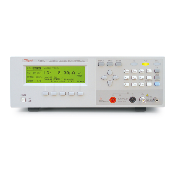
- Page 1 OPERATION MANUAL TH2689/TH2689A Capacitor Leakage Current/IR Meter...
-
Page 2: Table Of Contents
TH2689/89A Operation manual Content CHAPTER 1 INTRODUCTION..................2-1 1.1 I ....................... 2-1 NTRODUCTION 1.2 C ........................2-1 ONDITION 1.2.1 P ........................2-1 OWER 1.2.2 E .............. 2-1 NVIRONMENTAL TEMPERATURE AND HUMIDITY 1.2.3 W ........................2-2 1.2.4 C ........................ 2-2 AUTION 5.1 D... - Page 3 TH2689/89A Operation manual 4.2(W.V. TEST)........................39 4.2.1 T ......................39 EST PARAMETER 4.2.2 T ........................39 EST SIGNAL 4.2.3 D ......................39 ISPLAY RANGE CHAPTER 5 REMOTE CONTROL ..................41 5.1 RS232C I ................... 41 NTERFACE NTRODUCTION 5.1.1 RS232C ..................... 41 CONNECTION 5.1.2 C...
-
Page 4: Chapter 1 Introduction
L.C.---------------0.000 uA~ 20.00 mA Test voltage/charging current: Test voltage LEV = 1.0V ~ 100V,resolution 0.1V = 101V ~ 800V,resolurion 1V; ±(0.5%+0.2V)[TH2689] = 101V ~ 500V,resolution 1V; ±(0.5%+0.2V)[TH2689A] Charging current LEV ≤ 100V:0.5 mA ~ 500 mA,resolution 0.5 mA > 100V: 0.5 mA ~ I ,... -
Page 5: Warm-Up
TH2689/89A Operation manual Reference working temperature: 20°C±8°C,humidity: < 80%RH Transportation temperature:0°C~55°C,humidity:≤ 93%RH 1.2.3 Warm-up Warm up time:≥ 20 min. 1.2.4 Caution Please do not operate the instrument in the places where is vibrative, dusty, under direct sunlight, or where there is corrosive air. -
Page 6: Insulation Intensity
TH2689/89A Operation manual 5.2.2 Insulation intensity Under the reference working condition,the rated voltage between powerterminal and shell is 1.5kV, 50Hz AC voltage is 1 Min.,no arc phenomenon. 5.2.3 Leakage current Leakage current is no larger than 3.5mA. 5.3 Electromagnetic compatibility Power instaneous sensitivity is based on GB6833.4... -
Page 7: Chapter 2 Instruction Of Front Panel
TH2689/89A Operation manual Chapter 2 Instruction of front panel 2.1 Instruction of front panel Figure 2-1 Figure 2-1 Instruction of front panel Name Instruction TH2689 or TH2689A Brand and model Capacitor Leakage Current/IR Meter POWER Switch on and off 220V/110V power... -
Page 8: Instruction Of Rear Panel
TH2689/89A Operation manual with highlight. UNKNOW INPUT:current sampling terminal Voltage output HV(-) :negative voltage output terminal; terminal HV(+) :voltage positive terminal; Connect with shielding layer of the component to be tested , in order to separate the Ground electromagnetic interface improve accuracy and stability. - Page 9 TH2689/89A Operation manual Figure 2-2 Instruction of rear panel Name Instruction Provide the universal serial communication interface for instrument and external device. All RS232C parameter setup and command are set and obtained by computer to realize the remote control. Provide...
-
Page 10: Chapter 3 Operation
TH2689/89A Operation manual Chapter 3 Operation 3.1 Connection of (DUT) Figure 3-1 Note: INPUT terminal is connected with positive terminal, HV(-)outputs negative voltage,and connects the negative terminal of DUT. -
Page 11: Operation
TH2689/89A Operation manual 3.2 Operation MAIN INDEX 3.2.1 Press to enter <MAIN INDEX> page,use direction key to move cursor ,press to enter the corresponded subfunction page, press to return to the previous test page. Shown as figure 3-2: FILE : file storage page;... -
Page 12: Seq. Test
TH2689/89A Operation manual test page COMPARE Compare function setting page FILE File storage page Calibration Calibration page Not for user 3.2.2 SEQ. TEST On this page,just press ,the instrument can finish charge, test, discharge automatically. 3.2.2.1 <SEQ.TEST> On <MAIN INDEX> page,use direction key to move cursor to“(1)... - Page 13 4 Voltage monitor 5 Current procedure 6 Softkey zone 7 Test parameter setup 3.2.2.3 Instruction of setting test parameter (1) Test voltage (LEV) , range 1V~800V (TH2689) / 1V~500V (TH2689A) Figure 3-4 Setup of test voltage...
- Page 14 TH2689/89A Operation manual Move cursor to “LEV:100.0V”,operate according to the table below: Coarse urning from small large , : 6.3→10.0→16.0→25.0→35.0→50.0→63.0→100.0→160.0→200.0→250.0→3 50.0→400.0→450.0→500.0(→550.0→600.0→630.0→800.0) Coarse turning , from large small : 6.3←10.0←16.0←25.0←35.0←50.0←63.0←100.0←160.0←200.0←250.0←3 50.0←400.0←450.0←500.0(←550.0←600.0←630.0←800.0) Fine turning,when LEV ≥ 100.0V,stepper is +1V; When LEV < 100.0V,stepper is +0.1V Fine turning,when LEV ≥...
- Page 15 TH2689/89A Operation manual Fine turning. Stepper is +0.5 mA; Fine turning. Stepper is -0.5 mA; Numberic key Input charging current value directly ( default unit is mA) , press ENTER to confirm (3) (RANG) ,small character A means AUTO,H means HOLD Figure 3-6 setup of range gear Move cursor to“RANG:...
- Page 16 TH2689/89A Operation manual Fast Middle Slow Note:the speed is slower and the test result is more stable. (5) (CHG T) ,range 0Sec~999Sec, Figure 3-8 setup of charging time Move cursor to “CHG T: 30S”, operate according to the table below:...
-
Page 17: Single Step Manual Test Page
TH2689/89A Operation manual Figure 3-9 Setup of delay test time Move cursor to“D T: 0.2S”, operate according to the table below: Coarse turning. When D T ≥ 100Sec,stepper is +10Sec; When D T < 100Sec,stepper is +1Sec; Coarse turning. When D T > 100Sec, stepper is -10Sec;... - Page 18 TH2689/89A Operation manual step;and press to tes;finally press return to discharge status. 3.2.3.1 <STEP TEST> On <MAIN INDEX> page,use direction key to move cursor to“(2) STEP TEST”, press to enter <STEP TEST>, there are 2 pages on <STEP TEST>,shown as figure 3-11:...
-
Page 19: Continues Auto Test Page
TH2689/89A Operation manual 3.2.3.2 Instruction of setting parameter (1)LEV、CC、RANG、SPEED see §3.2.2.3 (2)Trigger mode (TRIG) Figure 3-12 setup of trigger mode Move cursor to“TRIG: INT”, operate according to the table below: Internal auto trigger Manual trigger External trigger ※Note:BUS(bus trigger)is set by bus command 3.2.4 Continues auto test page... -
Page 20: Null Test Page
TH2689/89A Operation manual 图 3-13(a) CONT TEST 第一页选项 图 3-13(b) CONT TEST page 2 ※Note: (1) In CHARGE status, parameter can’t be set, in TEST status, only RANG and SPEED can be set. (2)In the status of CHARGE and TEST,press to return to discharge status. -
Page 21: Aluminium Foil Withstanding Voltage Test Page
TH2689/89A Operation manual Figure 3-14 Null test page 3.2.5.2 Parameter setup (1) LEV, CC is only used to display the current test parameter, no modification (2)RANG displays the range in the process of null. (3)Null function setup setting(OPEN) Figure 3-15 Move cursor to“OPEN:... - Page 22 2:display the final tested voltage and time when test ends; 3:if the test is cancelled in the process,only press to enter discharge status at anytime. 3.2.6.3 Parameter setting (1) Rated feather withstanding voltage ( Vf) : range 1V~800V (TH2689) / 1V~...
- Page 23 TH2689/89A Operation manual 500V(TH2689A) Figure 3-17 Move cursor to“Vf: 100.0V”,operate according to the table below: Coarse turning,from small to large: 6.3→10.0→16.0→25.0→35.0→50.0→63.0→100.0→160.0→200.0→250.0→350.0→ 400.0→450.0→500.0(→550.0→600.0→630.0→800.0) Coarse turning,from large to small: 6.3←10.0←16.0←25.0←35.0←50.0←63.0←100.0←160.0←200.0←250.0←350.0← 400.0←450.0←500.0(←550.0←600.0←630.0←800.0) Fine turning,stepped is +0.1V Fine turning,stepper is -0.1V Numer Input rated feather withstanding voltage value directly, and press ENTER to confirm ic key (2)W.V charge current(CC)...
- Page 24 TH2689/89A Operation manual Move cursor to “CC: 15.0mA”,operate according to the table below: Coarse turning. Stepper is +5.0mA; Coarse turning. Stepper is -5.0mA; Fine turning. Stepper is +0.5 mA; Fine turning. Stepper is -0.5 mA; Numeric key Input W.V charge current value directly, press ENTER to confirm (3)W.V test time(Td)...
- Page 25 TH2689/89A Operation manual Figure 3-20 charge time high limit setup Move cursor to “ChgTd: 50S”,operate according to the table below: Coarse turning. Stepper is +30Sec; Coarse turning. Stepper is -30Sec; Fine turning. Stepper is +5Sec; Fine turning. Stepper is -5Sec;...
-
Page 26: Compare Function Setting Page
TH2689/89A Operation manual 3.2.7 Compare function setting page 3.2.7.1 <COMPARE> On <MAIN INDEX> page,use direction key to move cursor to“(6) COMPARE”,and press to enter <COMPARE>(shown as 3-21). Figure 3-21 COMPARE 3.2.7.2 Parameter setting (1)PARAMETER:display the current compare parameter mode, it can’t be modified here, if modify see §3.2.9.1 。... -
Page 27: File Storage Page
TH2689/89A Operation manual Figure 3-23 Turn on the comparator upper limit function Turn off the comparator upper limit function Numeric key Input comparator upper limit function value directly (4) (LOWER) Refer to comparator upper limit setting. 3.2.8 File storage page 3.2.8.1 <FILE>... - Page 28 TH2689/89A Operation manual Rename file Delete file 3.2.8.2 File storage operation (1)0~9 files can be saved,No. 10 file is the default file which is used to recover the default status. (2)“----------”means there is no corresponding file storage (3)Stored file flowchart Press ,page turns to file input,shown as figure 3-25:...
-
Page 29: System Configuration Page
TH2689/89A Operation manual Figure 3-27 3.2.9 System configuration page Press ,enter<SYSTEM CONFIG>,there are 3 pages , shown as figure 3-28: Figure 3-28(a)SYSTEM CONFIG page 1 Figure 3-28(b)SYSTEM CONFIG page 2... - Page 30 TH2689/89A Operation manual Figure 3-28(c)SYSTEM CONFIG page 3 3.2.9.1 System parameter setting (1) (PARAMETER) ,default is L.C. Figure 3-29 Move cursor to “PARAMETER”: Parameter is set as(I.R.) Parameter is set as(L.C.) (2) (KEY LOCK) ,default is OFF Figure 3-30 Move cursor to“KEY LOCK”:...
- Page 31 TH2689/89A Operation manual (3) (CHG TIME) ,default is Vm=Vs Figure 3-31 Move cursor to “CHG TIME”: Calculate the charge time fron Vm=Vs Calculate the charge time from Vm=0V ※According to JIS ( Japanese Industrial Standards, ) , after the DUT is charged to the rated working voltage,...
- Page 32 TH2689/89A Operation manual Figure 3-33 Move cursor to “AVERAGE”: Numeric key Input average time directly (6) (BEEP SET) ,default is ON Figure 3-34 Move cursor to “BEEP SET”: Sound Silence (7) (BEEP MODE) ,default is FAIL Figure 3-35...
- Page 33 TH2689/89A Operation manual Move cursor to“BEEP MODE”: Alarm when the test result is pass in COMPARE Alarm when the test result is fail in COMPARE Turn to the second page of SYSTEM CONFIG (8)HANDLE(HDL SET) ,default is ON Figure 3-36 HANDLER Move cursor to “HDL SET”:...
- Page 34 TH2689/89A Operation manual CLEAR mode,when using HANDLER interface,before testing,clear out the output signal of last test(PASS or FAIL) HOLD mode,when using HANDLER,the output signal (PASS or FAIL)will be changed until the next result being changed (10) (TRIGDELAY) ,range 0~9999mSec,default is 0mSec Figure 3-38 Move cursor to “TRIGDELAY”:...
- Page 35 TH2689/89A Operation manual Figure 3-40 Bus mode setting Move cursor to“BUS MODE”: Use GPIB interface Use RS232 interface No bus control (13) (GPIB ADDR) ,range 00~30,default is 08 Figure 3-41 Move cursor to“GPIB ADDR”: Numeric key Input GPIB address directly...
- Page 36 TH2689/89A Operation manual Figure 3-42(a) Figure 3-42(b) Move cursor to“BAUD RATE”: Switch as figure 3-42 Select 600,1200,4800,9600,19200,28800 baud rate …… Turn to the third page of SYSTEM CONFIG (15) (EOS CODE) ,default is ASCII code 0AH Figure 3-43...
- Page 37 TH2689/89A Operation manual Move cursor to“EOS CODE”: The selection of Eos data is ended with 0AH The selection of Eos data is ended with 0DH The selection of Eos data is ended with 0DH0AH Back to the second page of SYSTEM CONFIG (16)...
- Page 38 TH2689/89A Operation manual When waiting for the external trigger signal, the tested voltage is displayed immediately When waiting for the external trigger signal, the tested voltage is not displayed (18) (PASS WORD) ,the default password is “2689” Figure 3-46 Move cursor to “PASS WORD”...
- Page 39 TH2689/89A Operation manual Figure 3-48 Use numeric key to input new password, press to confirm and reinput the new password can be saved. Figure 3-49 (19) (CONTRAST) ,range 0~31,the default is 15 Figure 3-50 Move cursor to“CONTRAST”: (20) (KEY BEEP) ,the default is ON...
- Page 40 TH2689/89A Operation manual Move cursor to“KEY BEEP”: Sound No sound...
-
Page 41: Chapter 4 Test Performance
TH2689/89A Operation manual Chapter 4 Test performance 4.1(L.C./I.R. TEST) 4.1.1 Parameter Leakage current test:L.C.(Leakage Current) ,I.R.(Isolated Resistance) 4.1.2 Test signal Test voltage LEV = 1.0V ~ 100V,resolution is 0.1V = 101V ~ V ,resolution is 1V; ±(0.5%+0.2V) Charge current LEV ≤ 100V:0.5 mA ~ 500 mA,resolution is 0.5 mA >... -
Page 42: Basic Accuracy
Clear out the leakage current in the whole return circuit. 4.2(W.V. TEST) 4.2.1 Test parameter Rising time Tr unit:Sec Feather withstanding voltage Vt unit:V 4.2.2 Test signal Charge current 0.5 mA ~ 80 mA; (TH2689) 0.5 mA ~ 130 mA; (TH2689A) step 0.5mA 4.2.3 Display range Tr --------------- 110mSec~600Sec... - Page 43 TH2689/89A Operation manual Vt --------------- 1.0V~V = 800V(TH2689) = 500V(TH2689A)...
-
Page 44: Chapter 5 Remote Control
TH2689 has the RS232C serial interface and the parallel GPIB (optional) interface. Both interfaces can be used to remotely control TH2689, but they can not be used at the same time. The two interfaces share the same program commands, but they have different hardware configurations and different communication protocols. - Page 45 Data Carrier Detect Data Terminal Ready Transmitted Data Received Data Signal Ground Common TH2689 only uses the smallest subset of the RS232C standard, the signal are listed as follows. Function Code 9 Pin Connector Pin Number Transmitted Data Received Data Signal Ground Common Note:The definition of serial interface pin is basically the same as that of the connector of...
-
Page 46: Communication With A Computer
5.1.2 Communication with a computer Diagram of connection to a controller: There may be the same between TH2689’s RS232 interface and a standard RS232C interface. You can make the connection cable by yourself according the diagram or order one from our company. - Page 47 TH2689/89A Operation manual intelligent instruments can be collected, as well as an auto test system can be composed conveniently with other test instrument. In the same bus, many test instruments can be connected simultaneously. In this instrument, the IEEE488.2standard is adopted, and the interface board can be selected and bought by user.
-
Page 48: Gpib Function
TH2689/89A Operation manual Figure 5-4 Double-piggyback Connector Superposition GPIB cable connection mode-2 : Figure 5-5 4-piggyback Connector Superposition 5.2.2 GPIB function TH2689's GPIB functions are listed in the following table. -
Page 49: Gpib Addressing
TH2689/89A Operation manual Function Code Complete Source Handshake capability Complete Acceptor Handshake capability Basic Talker; Talk-Only; unaddressed if MLA; no serial poll Basic Listener; unaddressed if MTA; no Listen Only Remote/Local capability Device Clear capability Device Trigger capability No Controller capability Drivers are open-collector 5.2.3 GPIB addressing... -
Page 50: Chapter 6 Command Reference
There are two types of command:GPIB sharing command and SCPI(standard command ofprogrammable instrument) command. GPIB sharing command is defined by IEEE488.2-1987, these commands are available in all devices, but TH2689 dosen’t support all sharing commands. SCPI command is a tree structure. -
Page 51: Scpi Order Structure
TH2689/89A Operation manual 6.2 SCPI Order structure Figure 6-1 SCPI command table Command Parameter Return value ABORt [无查询] CALCulate :LIMit {IR | LC} {IR | LC} :FORMat :BEEPer {FAIL | PASS} {FAIL | PASS} :CONDition {OFF | ON | 0 | 1} {0 | 1} :STATe... -
Page 52: Order Structure Instruction
TH2689/89A Operation manual WVTest :SOURce { <numeric_value> | MAX | MIN} <numeric_value> :VOLTage { <numeric_value> | MAX | MIN} <numeric_value> :CURRent :CONFigure { <numeric_value> | MAX | MIN} <numeric_value> :TEND { <numeric_value> | MAX | MIN} <numeric_value> :CHGTEND :MEASure [only for query] {CHG | TEST | DCHG} :STATe?... -
Page 53: Order Syntax
TH2689/89A Operation manual interrogation(?) :interrogation means query。 Comma(, ) :Comma is break of multi-parameter Space( ) :Space is the break of command and parameter Quote mark(‘ ’) :Single quotes means the content quoted by original sample, and the command analyze program doesn’t process on it Asterisk(*)... -
Page 54: Scpi Order Instruction
TH2689/89A Operation manual Ending character There are three kinds of ending character: [CARRIAGE RETURN](0Dh), [NEW LINE] (0Ah)and [CARRIAGE RETURN](0Dh)+[NEW LINE](0Ah). 6.4 SCPI order instruction 6.4.1 ABORt order system :ABORt parameter:None Return value:None Function:Breakout the processing system instantly, and reset the trigger 6.4.2 CALCulate order system... - Page 55 TH2689/89A Operation manual Function:send the comparator result Parameter:none Return value:{ 0 | 1 } Instruction:0 comparator result is FAIL comparator result is PASS :CALCulate}:LIMit:STATe { OFF | ON | 0 | 1} Function:set or query if set up comparator function Parameter:{ OFF | ON | 0 | 1}...
-
Page 56: Display Order System
TH2689/89A Operation manual 6.4.3 DISPlay order system :DISPlay:STATe? Function:query the currently-displayed function page Parameter:none Return value:{LCTEST | WVTEST | NULL | MAIN | SYSTEM} :DISPlay:LCTest Function:switch function page as LC TEST Parameter:none Return value:none :DISPlay:WVTest Function:switch function page as WV TEST Parameter:none... - Page 57 TH2689/89A Operation manual Instruction:numeric_value is 4(20mA) 、3(2mA) 、2(200uA) 、1(20uA)及 0(2uA) MIN 为 2uA MAX 为 20mA :LCTest:CONFigure:RANGe:AUTO { OFF | ON | 0 | 1} Function:set or query if set on auto switching bin mode Parameter:{OFF | ON | 0 | 1} Return value:{ 0 | 1}...
-
Page 58: Wvtest Order System
TH2689/89A Operation manual Return value:numeric_value,format is <NR3>,unit is VOLT 6.4.5 WVTest order system :WVTest:SOURce:VOLTage {<numeric_value> | MIN | MAX} Function:set or query the test voltage of WV function Parameter:{<numeric_value> | MIN | MAX} Return value:numeric_value Instruction:MIN 800V(TH2689) 500V(TH2689A) :WVTest:SOURce:CURRent {<numeric_value> | MIN | MAX} Function:set or query charge current of WV function... -
Page 59: Trigger Order System
TH2689/89A Operation manual :WVTest:MEASure:VEnd? Function:query the test voltage value when WV ends. Parameter:none Return value:numeric_value,format is <NR3>,unit is V 10. :WVTest:MEASure:DATA[:DATA]? Function:return the data saved in buffer area,and the number of data is defined by POINTs command Parameter:none Return value:query the responded data is <set1>:first group... -
Page 60: System Order System
TH2689/89A Operation manual Parameter:{FALL | RISI} Return value:{FALL | RISI} Instruction:FALL fall trigger RISI rise trigger 6.4.7 SYSTem order system :SYSTem:BEEPer[:IMMediate] Function:alarm once Parameter:none Return value:none :SYSTem:BEEPer:STATe {OFF | ON | 0 | 1} Function:set or query if beeper has been set on Parameter:{OFF | ON | 0 | 1}... -
Page 61: Error Information
TH2689/89A Operation manual Parameter:{<numeric_value> | MIN | MAX} Return value:numeric_value Instruction:MIN :SYSTem:PRESet Function:reset to preset status Parameter:none Return value:none 10. :SYSTem:ERRor? Function:query the error information Parameter:none Return value:numeric_value string Instruction:numeric_value error code string error string 6.5 Error information Common error table:... -
Page 62: Chapter 7 Sorting Interface Instruction
TH2689/89A Operation manual Chapter 7 Sorting interface instruction When using COMPARE, HANDLER is connected with external device and its connector is 24 core,the instruction of pin is as below. 7.1 HANDLER interface Figure 7-1 HANDLER interface Name /EXT TRIG /DISCHARGE /TEST 3,20... -
Page 63: The Jumper Set On Handler Board
TH2689/89A Operation manual 7.2 The jumper set on HANDLER board The jumper on HANDLER board is used to select internal or external power in outputting signal and controlling signal. warning: Be sure the power jack has been removed and operate after internal capacitor is discharged Note:In figure 7-2 and 7-1,“N”means the default jumper setting. -
Page 64: Handler Interface Signal Diagram
TH2689/89A Operation manual 7.3 HANDLER interface signal diagram (1)when in SEQ.TEST,HANDLER signal diagram /EXT TRIG Note 2 /CHARGE /TEST /DISCHARGE /ACQ /EOT Note 1 /PASS /FAIL Figure 7-2 SEQ.TEST ※Note 1:HANDLER is in CLEAR mode,enter test status to clear out the last compare result of PASS/FAIL signal. - Page 65 TH2689/89A Operation manual (2)when in STEP TEST,HANDLER interface signal diagram Note 2 /EXT TRIG /CHARGE /TEST /DISCHARGE /ACQ /EOT /PASS Note 1 /FAIL Figure 7-3 STEP TEST ※Note 1:When HANDLER is in HOLD mode,comparator result of PASS/FAIL signal is turned after the next result changes.
Need help?
Do you have a question about the TH2689 and is the answer not in the manual?
Questions and answers