Table of Contents
Advertisement
Advertisement
Table of Contents

Related Manuals for Tonghui TH2822


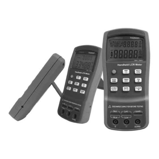
Summary of Contents for Tonghui TH2822
- Page 1 Model TH2822/TH2822A/TH2822C Dual Handheld LCR Meter Instruction Manual...
-
Page 2: Safety Summary
NON-PROFESSIONALS SHUOLD NOT OPEN THE REAR COVER Maintaining, substituting parts or adjusting the instrument should be made by professional maintenance personnel. Please contact relevant distributor or Tonghui’s after-sale service department. - Page 3 DO NOT REMOVE OR MODIFY THE INSTRUMENT Some replacements and unauthorized modifications might cause irreversible damage to the instrument. SAFETY WARNING Strictly follow the relevant safety statements in this manual involving safety, personnel injury, damage to the instrument, operation and environmental conditions causing poor test.
-
Page 4: Safety Guidelines
Safety Guidelines To ensure that you use this device safely, follow the safety guidelines listed below: This meter is for indoor use, altitude up to 2,000 m. For short-time outdoor use, precautions should be taken to avoid direct sunlight, water moisture, electromagnetic... -
Page 5: Safety Symbols
of 12VDC/150mA. If a power adapter is selected, please be sure to meet the safety requirements of a relevant IEC standard. battery using TH2822C rechargeable. charge non- rechargeable batteries. Safety Symbols This symbol is a warning and indicates that the user should refer to the operating instructions located in the manual. -
Page 6: Environmental Conditions
Environmental Conditions 0 °C to 40 °C Operating Environment Storage Humidity 0 – 80% R.H. Storage Environment -20 °C to +50 °C Pollution degree... -
Page 7: Table Of Contents
Contents Safety Summary ............1 Safety Guidelines ............3 Introduction ............... 9 Package Contents ........... 10 Front Panel Overview ..........12 Front Panel Display Descriptions ........13 Front Panel Buttons ............15 Button Function Definition ..........16 LCD Display Overview ..........17 LCD Display Descriptions .......... - Page 8 Operation Instruction..........30 Data hold mode (HOLD) ..........30 Data Record Mode (REC) ..........31 L/C/R/Z Select Mode ............ 33 D/Q/θ/ESR Select Mode ..........34 Test Frequency (FREQ)..........34 Tolerance Mode (TOL) ..........35 Auto LCR Mode ............37 Measurement Rate (RATE) .......... 39 Series/parallel Equivalent Mode ........
- Page 9 Connecting Instrument to PC ........67 Virtual Serial Port Configuration ........68 RMT Operation ............. 69 Command Protocols ............. 71 Command Reference ............ 77 Specifications ............84 General Specifications ..........84 Accuracy Specifications ..........87 Maintenance ............94 Service ................94 Cleaning................
-
Page 10: Introduction
TH2822 series provide the primary parameter of up to 40,000 readings, secondary parameter of 0.0001 reading resolution, the maximum measuring frequency of up to 100kHz, constant internal resistance of 100Ω... -
Page 11: Package Contents
All TH2822 series are equipped with the function of remote communication. The test data can be transferred to PC through a Mini USB connection, great for applications that require remote control and data acquisition. - Page 12 * This can be purchased as optional accessories. All contents are subject to actual package list or box. Please locate them from the original packaging to ensure nothing is missing. If in the case that an item is missing, please contact Tonghui or relevant distributor immediately.
-
Page 13: Front Panel Overview
Front Panel Overview Figure 1 - Front Panel Display (model TH2822C shown) -
Page 14: Front Panel Display Descriptions
—Crocodile clip Test Leads) 13. Standard mini USB port (for remote control) 14. 12VDC external power input (use with an external power adapter) *Backlight is not included in TH2822. ’ NOTE: Refer to the adapter s label for input ,... - Page 15 with improper power adapters may damage instrument. NOTE: Internal battery supply will be automatically cut off since the normal supply of external power. If the battery is rechargeable (TH2822C), the external power will charge the battery simultaneously. TH2822C is installed an independent charging controller---charging control is still done even at the state of power-off.
-
Page 16: Front Panel Buttons
Front Panel Buttons With the exception of the power button, all front panel buttons have specific colored labels on them. They are all marked in black, blue, or orange color. Each color has a specific representation, as described below: Black—the primary function,meaning that function will be set or configured upon pressing it. -
Page 17: Button Function Definition
HOLD UTIL θ D/Q/ FREQ /ESR L/C/R/Z RATE CLEAR AUTO Figure 2 –Button Display (Model TH2822C shown) Button Function Definition 1. Power ON/OFF Button 2. Frequency/Record Mode Button 3. Remote Control/Backlight Button 4. Readings Hold/Utility Menu Button 5. Tolerance mode/ Menu Selection Button 6.... -
Page 18: Lcd Display Overview
LCD Display Overview AUTO θQ MAXAVGMIN Ω FASTSLOW 2105% μ H μ Ω Figure 3 - LCD Indicator Display LCD Display Descriptions 1. LCRZ – Primary display indicator 2. MAX – Maximum reading indicator in the record mode 3. AVG – Average reading indicator in the record mode 4. - Page 19 7. D – Dissipation indicator 8. Q – Quality factor indicator – Secondary display – Beeper tone indicator for tolerance mode 11. deg – Phase angle (θ) units indicator 12. Ω – ESR(ohm) units indicator 13. % - Percentage indicator (in tolerance mode) 14.
-
Page 20: Special Display Indicators
Indicates open clear if you press the CLEAR button Error indication Indicates correction (open/short clear) mode Indicates damaged or open fuse AD converter error(UNK) AD converter error(END) Test Port TH2822 series are creatively designed to combine 3- terminal port and 5-terminal port, which makes the... - Page 21 However this configuration has low testing accuracy. For the improvement of accuracy when using external testing leads, TH2822 series are designed with 5- terminal testing slots and exclusive test fixture to ensure complete external 4-terminal test and measuring accuracy.
-
Page 22: Powering Instrument
The two power modes can be automatically switched without interruption. Installing Battery TH2822 series can adopt battery for power supply so that you can take measurements whenever and wherever without many preparations. 9V alkaline batteries used in TH2822/TH2822A are non-rechargeable. - Page 23 TH2822C applies 8.4V rechargeable battery with LH-200H7C as the reference type. Do not use non- rechargeable batteries with the exception of emergency cases. The reason is that the charging circuit will operate once the instrument is connected to external power. To Install the Battery: 1....
- Page 24 Figure 5- Back Cover...
-
Page 25: Connecting External Power Source
Figure 6- Battery Compartment Connecting External Power Source Some models of TH2822 series are equipped with standard external power adapters, which can use external source. WARNING: Use the included or specified adapter only. Confirm power parameters be ones that adapters require before use. - Page 26 To connect the adapter, do the following: 1. If a battery is installed, please check the battery compartment again that the polarity of the battery matches the polarity as indicated by the labels inside the compartment. WARNING: DO NOT, at any time, connect an external power adapter when a battery is installed incorrectly or a non-rechargeable battery is inserted in a rechargeable instrument.
-
Page 27: Low Battery Indication
12VDC Input AC Adapter Figure 7-Connecting AC Adapter to Meter NOTE: The meter will automatically switch to consume power from the AC adapter instead of the battery when an AC adapter is plugged in and consume the power normally. In this event, if the battery installed correctly is rechargeable (for instance, TH2822C), charging controller will be driven at the same time no matter the instrument is on or off. -
Page 28: Backlight Display
Backlight Display Only TH2822A/C meters have Backlight display that can allow you to see the LCD display in dark conditions, TH2822 doesn’t support backlight. To turn on the back light, you should press the button for a long time. -
Page 29: Charge Display
Charge Display The power circuit of TH2822/A is non-rechargeable. When the external power adapter is plugged in, the power mode will automatically switched and the battery power circuit will be cut off. - Page 30 instead, the battery will be charged again after a charge circle. NOTE: A new charge circle will begin as soon as an external power is connected. WARNING: If the instrument has rechargeable circuit, DO NOT connect to an external power when a non-rechargeable battery is installed.
-
Page 31: Operation Instruction
Operation Instruction Data hold mode (HOLD) The data hold function allows the user to freeze the display data. The data displayed on LCD will not update upon the phase of test until data hold is turned off. Turn On Data Hold To use data hold, press the HOLD button. -
Page 32: Data Record Mode (Rec)
Data Record Mode (REC) If the data stability of tested components is poor and the data fluctuates in a range, data record mode can aid the reading of data. This mode is used for dynamically recording maximum, minimum, and average values in a range. Enable Static Recording Press and hold down the REC button for a long time to enter the data recording mode. - Page 33 Recording State This is the default mode when enabling static recording. In this mode, LCD will display “MAX AVG MIN” indicator. In a relatively stable range of test data, a beep tone will sound once a recording has been stored. NOTE: When the data fluctuation range is upwards of 1%, data record will dynamically be refreshed.
-
Page 34: L/C/R/Z Select Mode
Average Display Press REC button until the “AVG” indicator is shown on display. This indicates that the value in the primary display represents the recorded average value. Disable Static Recording To exit this mode, press and hold the REC button for a long time. -
Page 35: D/Q/Θ/Esr Select Mode
D (Dissipation factor), Q (Quality factor), θ (Phase angle), and ESR (Equivalent series resistance). Test Frequency (FREQ) TH2822 series handheld LCR meters apply AC signal to DUT for measurement. Frequency is among the main parameters of AC signal. By the presence of component’s non-ideality and distributed parameters,... -
Page 36: Tolerance Mode (Tol)
Tolerance mode, nominal value and sorting limit just come into play on primary parameters. The selectable ranges for sorting are as follows: 1%,5%,10%, 20% (20% is not for TH2822). When entering tolerance mode, the data indicated in the primary display will be recorded as nominal value. - Page 37 Use Tolerance Mode To use the tolerance mode as the process shown below: 1. Select the desired primary measurement mode by pressing L/C/R/Z button. 2. Configure the proper test frequency and series/parallel equivalent mode. 3. Perform the operation of CLEAR appropriately if necessary.
-
Page 38: Auto Lcr Mode
10% or 20%, which will be shown on LCD accordingly. 7. Changing test component, an audible tone will be heard. One single “beep” or tone means the component is within tolerance. Three “beeps” or tone means the component is out of tolerance. - Page 39 property of component according to the test result. It is quite convenient for the measurements of mixed and unknown components. Enable Auto LCR Mode Long press of AUTO button will activate auto LCR mode. The “AUTO” indicator on LCD indicates that auto LCR mode is activated.
-
Page 40: Measurement Rate (Rate)
Disable Auto LCR Mode Long press the AUTO button again will disable auto LCR mode. In addition, this mode will not continue through changing the primary and secondary modes, series/parallel equivalent mode and frequency mode. “AUTO” indicator on LCD will disappear when auto LCR mode is turned off. - Page 41 equivalent models used in LCR meters, which are series model and parallel model. Figure 8-Series and Parallel Equivalent Models of Inductors and Capacitors Appropriate equivalent modes could help to gain better measurement results. Generally, Series mode is better for components with low impedance (blow 100Ω),while parallel mode for components with high impedance (over 10kΩ).
-
Page 42: Utility Menu (Util)
Default Equivalent Mode When select primary parameter, equivalent mode varies with primary parameter: For capacitors and resistors, default equivalent mode is PAL; for inductors, is SER. Utility Menu (UTIL) The LCR meter has a built-in utility menu that allows you to configure some user preferences and settings. The buttons used to set and control the menu are colored in blue. - Page 43 Configuration and Settings The following contents are included in the utility menu: Table 2-Utility Menu Options and Settings Menu Options Settings/Parameters bEEP ON / OFF AoFF 5 / 15 / 30 / 60 / OFF PrE / Set yES / NO bAtt Battery Voltage Uses of these menu options are as follows:...
- Page 44 NOTE: The change of settings has different application effects in accordance with different exiting mode. See “Exit Utility Menu” section (Saving and Exiting, Exiting without Saving) for details. Beep Sound Setup (bEEP) The “bEEP” menu option allows the user to enable or disable the beep sound for every key press.
- Page 45 display shows “AoFF”, push the and arrow keys to select the timer setting. The settings will be shown on the secondary display as Table 3. When AoFF is effective, this timer is always counting continuously; when the configured time is up, the meter will make an audible “beep”...
- Page 46 The setting will be immediately effective. But this state will not saved if choose “Exiting without saving”; “Saving and exiting” should be implemented if this setting needs to be effective after restarting. Default Setting: 5 Power-up State (PuP) The “PuP” menu option allows user to configure the power-up state of the LCR meter, allowing user to restore settings saved into internal EEPROM memory at power-up.
- Page 47 NOTE: Exiting mode decides whether to implement SEt. At “Exiting without saving”, SEt is ineffective; while at “Saving and Exiting”, SEt setting will be effective. Default Setting: PrE Configure and Save Power-up State Procedure to configure and save power-up state is as follows: 1.
- Page 48 either or button to change the settings so that the secondary display shows “Set”. 5. Press the UTIL button to check whether other desirable setups have already been set. With all settings done, exit the menu by long press of the UTIL button.
- Page 49 Reset Default Settings (dEF) The “dEF” option is used to reset the current measuring setup and optional settings in utility menu to default settings. These default settings are as below:...
- Page 50 Table 4 - Instrument Default Settings Settings Default Configuration Primary Function C (capacitance) Secondary Function None (frequency) Auto LCR function Equivalent Method SER (series) Measurement Frequency 1kHz Measurement Speed Slow (SLOW) Tolerance Mode Beep Sound Auto Power-off Timing 5 minutes Stored Measurement clear Setup...
- Page 51 In “dEF” option, push either or button to choose “NO” or “yES”. “NO” means the instrument will not be set back to default. “yES” indicates to reset all settings to default and to clear previously stored setup. Default Setting: No NOTE: Exiting mode also decides whether or not to perform “yES”...
- Page 52 Exit Utility Menu There are two methods for exiting the utility menu: Saving and Exiting, Exiting without Saving. The former saves all the changed settings before exiting, and the latter exits the menu without saving any changes. Saving and Exiting To save all utility menu option settings and to exit the menu, press and hold down the UTIL button for a long time.
-
Page 53: Clear Functions (Clear)
any front panel buttons except UTIL, , and POWER. PuP and dEF operation will be ineffective. Settings, such as “bEEP” and “AoFF” will not be saved in the non-volatile memory but still be temporarily efficient before power-off. Clear Functions (CLEAR) There are two functions under CLEAR: Open Clear and Short Clear. - Page 54 Open Clear First select frequency to clear and keep test clip and test slot be open. Enter into clear by the press of CLEAR, and a moment later the OPEN indicator will appear on secondary display after the automatic measurement judging. If user decides to perform open clear, another press of CLEAR should be done.
- Page 55 Short Clear First choose test frequency to clear and then insert a short plate to test slot. If SMD test tweezers or test clip is used, the short plate should short the test terminal. Enter into clear by the press of CLEAR, and a moment later the SHrT indicator will appear on secondary display after the automatic measurement judging.
- Page 56 Quick Clear Procedure Below is an example of steps to do open or short clear: 1. Select the primary and secondary function mode for measurement; 2. Select test frequency; 3. Select equivalent mode; 4. Keep the test terminal open to perform open clear;...
-
Page 57: Remote Control (Rmt)
accordance with advanced impedance network principle, the instrument performs clear operation. Though the complex impedance is cleared, the displayed parameter is just one of the elements of impedance, so it is cleared too. 4. After a long time of continuous use, the meter will be affected by the temperature environment and test fixtures, test leads and contact resistance will change. - Page 58 burned out, the “FUSE” indicator will appear on the primary display and an internal “beep” will sound continuously. In this situation, none of the function buttons can be operated and all other meter functions will be disabled. Figure 11-Fuse Display In the event that the above screen is displayed, the instrument should be powered off.
-
Page 59: Quick Start Guide
NOTE: Both fuse damage and none output of test signal caused by signal source fault will make “FUSE” alarm. Quick Start Guide CAUTION • Do not measure a capacitor that is not fully discharged. Connecting a charged or partially charged capacitor to the input terminals will damage the instrument. -
Page 60: Inductance Measurement
• Do not leave the instrument exposed to explosive, direct sun-lighting and overheating environments. • Before removing the cover, ensure that none DUT is connected to the meter and the instrument is disconnected from any circuit and is powered OFF. NOTE: To achieve optimum precision, please refer to “Clear Function”... -
Page 61: Measured Values
5. Press the D/Q/θ/ESR button to select the desired secondary parameter. 6. Read the readings on LCD for inductance measured values. TH2822C AUTO μH 100Hz - 100kHz Handheld LCR Meter HOLD UTIL θ D/Q/ FREQ /ESR L/C/R/Z RATE CLEAR AUTO Figure 12- Inductance Measurement Below are TH26027A,TH26009C,TH26029C 4- terminal test accessories:... - Page 62 TH26029C SMD KELVIN TWEEZER GUARD TH26009C SMD KELVIN TWEEZER GUARD TH26027A KELVIN CLIP GUARD Figure 13- 4-terminal Test Accessories...
-
Page 63: Capacitance Measurement
Capacitance Measurement WARNING: Before testing, ensure that the tested capacitor has been fully discharged. 1. Press the POWER button for a long time to turn on the meter. 2. Press the L/C/R/Z button until “C” is displayed on the screen to select capacitance measurement. 3. - Page 64 6. Press the D/Q/θ/ESR button to select the desired secondary parameter. 7. Read the readings on LCD for capacitance measured values. TH2822C AUTO 100Hz - 100kHz Handheld LCR Meter HOLD UTIL θ D/Q/ FREQ /ESR L/C/R/Z RATE CLEAR AUTO Figure 14- Capacitance Measurement...
-
Page 65: Resistance Measurement
Resistance Measurement 1. Press the POWER button for a long time to turn on the instrument. 2. Press the L/C/R/Z button until “R” is displayed on the screen to select inductance measurement. 3. Insert a resistor into test slots or connect a tested resistor through a proper test accessory (e.g., banana plug-crocodile clip test leads, test fixture or SMD test tweezers). - Page 66 TH2822C AUTO Ω 100Hz - 100kHz Handheld LCR Meter HOLD UTIL θ D/Q/ FREQ /ESR L/C/R/Z RATE CLEAR AUTO Figure 15- Resistance Measurement...
-
Page 67: Impedance Measurement
Impedance Measurement 1. Press the POWER button for a long time to turn on the instrument. 2. Press the L/C/R/Z button until “Z” is displayed on the screen to select impedance measurement. 3. Insert impedance (resistor, capacitor or inductor) into test slots or connect tested impedance through a proper test accessory (i.e., banana plug-crocodile clip test leads, test fixture or SMD test tweezers). -
Page 68: Remote Communication
Follow the below procedures for connection setup. 1. Install USB driver from CD or download the USB driver from www.tonghui.com.cn. 2. With a Mini-USB cable, connect one end of it to the LCR meter and the other end to an available USB port on PC. -
Page 69: Virtual Serial Port Configuration
6. Open the control software and use the assigned serial number to communicate with the handheld LCR meter. You can Download the FastAccess PC communication software from our web site (www.tonghui.com.cn) for a demo use. TH2822C AUTO θQ MAXAVGMIN Ω... -
Page 70: Rmt Operation
• Baudrate:9600 • Data bits: 8 • Parity: None • Stop bits: 1 • Flow Control: None Upon the installation of USB driver, if the default assigned by serial port does not match to above configuration, please modify it as the following process: Open Windows device manager→... - Page 71 Remote Mode Upon the acceptance of any commands from PC, the meter will be automatically set into remote mode. In this mode, the LCD display will show “RMT” indicator. When this is shown, all front panel button will be locked and disabled, except for RMT and POWER buttons.
-
Page 72: Command Protocols
RMT button to return panel operation and then enter into Auto Fetch mode by another press of RMT. Command Protocols Overview TH2822 series support SCPI commands with ASCII character strings transmitting control commands and returning query information and data and with a... - Page 73 Common commands usually come with the asterisk “*” character, and may include parameters. Some examples of Common command like: *IDN?, *GTL, *LLO. TH2822 series support a few common commands. See the following command descriptions for more details. Termination Character A terminator is a character sent by a host, which identifies the end of a command line.
- Page 74 <CR> (Carriage Return, ASC(&H0D)) ; <LF> (Line Feed, ASC(&H0A)); <CR><LF> Returned Result After the meter executes a query command, the return of the result will be in the following format: <Result> + <CR> <LF> CR is Carriage Return and LF is Line Feed. For example, in inquiring measured results (FETCH?), the format of the printed data will be shown as the following:...
- Page 75 Table 4 - Data Type Data Type Explanation Example <NR1> Integer +800,-200,100,-50 <NR2> Real +1.56,-0.001,10.5 This representation has an explicit +2.345678E+04 <NR3> radix point and an -1.345678E-01 exponent A parameter for Boolean setting. <Boolean> Always return “0” ON or OFF or “1”...
- Page 76 Syntax Explanation Symbol Colon means to enter into next command level Separate another command at the same command level common command multi-parameter delimiter ? inquiry Space, separate commands from parameters “ ” quoting part Symbols in Command Explanations Below symbols are used for the description of command format, which are not the constituting part of command.
- Page 77 Abbreviation, upper case and lower case commands 1. There are two command formats: complete format and abbreviated format. In the following command description, capital section of the complete commands shows abbreviations format. It has the same effect of sending abbreviated and complete commands. 2....
-
Page 78: Command Reference
Command Reference Common Command *IDN? Query instrument ID. Return: <instrument model>, <firmware version>, <serial number> *LLO Local Lockout. This means that all front panel buttons, including the RMT key is not available. (POWER button is enabled.) *GTL Go to local and remove local lockout. If *LLO is sent, the only way to operate front panel is to go to *GTL. - Page 79 SCPI Commands FREQuency Subsystem FREQuency <value> Description: Set measurement frequency Parameters are 100, 120, 1000, 10000,100000 or 100hz,120hz,1khz,10khz,100khz (model supported) Example: FREQuency 100hz Set 100Hz frequency FREQuency? Description: Query the measurement frequency Return: < 100hz,120hz, 1khz, 10khz,100khz> FUNCtion subsystem FUNCtion:impa < L | C | R | Z > Description: Select primary parameter Example: FUNCtion:impa L Selects L as primary parameter...
- Page 80 FUNCtion:impb? Description: Query secondary parameter Return: <D, Q, THETA, ESR, NULL> FUNCtion:EQUivalent < SERies | parallel | PAL > Description: Set equivalent mode Parameters: SERies — series mode Parallel — parallel mode PAL — parallel mode Example: FUNCtion:EQUivalent SERies Set series mode FUNCtion:EQUivalent? Description: Query the equivalent mode Return: <SER, PAL>...
- Page 81 CALCulate:TOLerance:VALUe? Description: Query the percentage value of tolerance Return: NR3 or ----- (exceeding data range) CALCulate:TOLerance:RANGe < 1 | 5 | 10 | 20 > Description: Set tolerance range as 1%,5%,10% or 20% (20% not available for some models ) Example: CALCulate:TOLerance:RANGe 1 Set 1% tolerance range CALCulate:TOLerance:RANGe?
- Page 82 CALCulate:RECording:MINimum? Description: Query the minimum value of recording function Return: <NR3, NR3> (primary and secondary parameters, when data exceeds limits or there is no data, what returns is “----“) CALCulate:RECording:AVERage? Description: Query the average value of recording function Return: <NR3, NR3> (primary and secondary parameters, when data exceeds limits or there is no data, what returns is “----“) CALCulate:RECording:PRESent?
- Page 83 Summary of Supported SCPI Commands Table 2 - Summary of SCPI Commands Command Parameter Explanation FREQuency <Value> Set Test Frequency FREQuency? Query Test Frequency FUNCtion :impa <Literal> Select primary display parameter :impa? Query primary display parameter :impb <Literal> Select secondary display parameter :impb? Query secondary display...
- Page 84 :MINimum? Query min. value of recording :AVERage? Query average value of recording :PRESent? Query present value of recording FETCh? Query measurement result Error Codes If the received commands or parameters from bus contain errors, the meter will terminate the analysis and execution commands.
-
Page 85: Specifications
Specifications Below is the general specification and the accuracy specification of TH2822 series and applicable to TH2822, TH2822A, TH2822C. Declaration: The specifications are subject to change without notice. *NOTE: 120Hz is the rated frequency. The actual frequency is 120.048Hz. General Specifications... - Page 86 1%,5% , 10% , 20% TH2822A/C Input Protection Fuse 0.1A / 63V Interface Mini-USB (virtual serial port) Test Signal TH2822 100Hz,*120Hz,1kHz Signal TH2822A 100Hz,*120Hz,1kHz,10kHz Frequency 100Hz,*120Hz,1kHz,10kHz, TH2822C 100kHz Test Signal Level 0.6Vrms 100Ω Output Impedance Display Display LCD primary-secondary dual display...
- Page 87 Parameter 0.0000W -- 999.9W 0.0001W 0.0000 -- 9.999 0.0001 0.0000 -- 9999 0.0001 θ -179.9° -- 179.9° 0.01° Power Supply TH2822/A IEC 6LR61,9V Alkaline battery Battery LH-200H7C,8.4V Ni-MH Model TH2822C 200mAH rechargeable battery Input:220V(1± 10% ), 50Hz(1 AC Adapter ±5%) Output:12V -15V DC...
-
Page 88: Accuracy Specifications
General Temperature 0℃ -- 40℃ Operation Condition ≤90% R.H. Relative Humidity Weight 350g 190mm ´ 90mm ´ Dimensions (H ´ W ´ D) 41mm IEC 61010-1:2001 Safety and EMC compliance IEC 61326-2-1:2005 Accuracy Specifications Notices: 1. Environment temperature:23℃±5℃; Humidity: ≤75% R.H. 2.... - Page 89 s—series equivalent; p—parallel equivalent; e—accuracy 9. Some parameters cannot be expressed as the way of data sheet; therefore they can just be converted by formulas according to corresponding results. Inductance (L) and Quality Factor (Q) Equi- Accuracy Range Display Range valent De * Mode...
- Page 90 ∼ 1000mH 400.0mH 999.99mH 0.80%+3 0.0080 Parallel ∼ 400mH 40.00mH 399.99mH 0.35%+2 0.0035 Parallel ∼ ---- 40mH 4.000mH 39.999mH 0.25%+2 0.0025 ∼ 400.0uH 3.9999mH 0.30%+2 0.0030 Series ∼ 400μH 399.99μH 40.00uH 0.45%+2 0.0045 Series ∼ 40μH 39.99μH 0.00uH 1.40%+5 ------ Series ∼...
- Page 91 Capacitance(C) and Dissipation (D) Equi- Accuracy Range Display Range valent Mode ∼ ±0.0500 20mF 4.000mF 20.000mF 5.00%+5 Series ∼ 400.0μF ±0.0100 3.9999mF 1.00%+3 Series ∼ 400μF 40.00μF 399.99μF ±0.0035 0.35%+2 Series ∼ 40μF 4.000μF 39.999μF ±0.0025 0.25%+2 Series ∼ 4μF 3.9999μF ±0.0025 ----...
- Page 92 ∼ 100μF 40.00μF ±0.0300 100.00μF 3.00%+5 Series ∼ 40μF 4.000μF 39.999μF ±0.0150 1.50%+3 Series ∼ 4μF 3.9999μF ±0.0035 400.0nF 0.35%+2 Series ∼ ±0.0025 400nF 40.00nF 399.99nF 0.25%+2 Series ∼ ±0.0025 ---- 40nF 4.000nF 39.999nF 0.25%+2 ∼ ±0.0025 400.0pF 3.9999nF 0.25%+2 Parallel ∼...
- Page 93 θ ( ) ( ) Impedance and Phase Angle Accuracy Equi- Range Display Range valent θe Mode ±1.75° 10MΩ 4.000MΩ∼10.000MΩ 3.00%+5 Parallel ±0.75° 4MΩ 400.0kΩ∼3.9999MΩ 1.25%+3 Parallel ±0.25° 400kΩ 40.00kΩ∼399.99kΩ 0.35%+2 Parallel ±0.15° 40kΩ 4.000kΩ∼39.999kΩ 0.25%+2 Parallel ±0.15° 4kΩ 400.0Ω∼3.9999kΩ 0.25%+2 ---- ±0.15°...
- Page 94 Equivalent Series Resistance Accuracy of equivalent series resistance is calculated by below formula: φ ± × Rse = Where, is measured reactance, π 2 π φ is the phase angle accuracy, π φ θ × : Notice the accuracies of ESR and Rs are same. Equivalent Parallel Resistance Accuracy of equivalent series resistance is calculated according to the below formula:...
-
Page 95: Maintenance
Maintenance WARNING: Do not perform any service by yourself. Service should only be done by qualified personnel and trained technicians. WARNING: Beware of liquid and residues, especially conductive matter. Service If the instrument fails to power on, first check battery, external source and power sockets and the validity of buttons. -
Page 96: Cleaning
Cleaning Before cleaning this meter, make sure the power is OFF and remove external AC adapter if one is used. To avoid electrical shock or damaging the meter, prevent water from getting inside the case. In the case that water gets inside, remove the battery immediately and do not operate the instrument immediately. -
Page 97: Limited Warranty
Tonghui will, without charge, repair or replace, at its option, defective product or component parts. Returned product must be accompanied by proof of the purchase date in the form of a sales receipt and the included accessories.
Need help?
Do you have a question about the TH2822 and is the answer not in the manual?
Questions and answers